
|
|
1.IntroductionClinical applications for early diagnosis and patient monitoring as well as basic studies on physiological optics and vision science have benefited in the last few years from the development of reliable wavefront sensors able to measure human eye aberrations, and optical components and devices able to compensate them. This rapidly growing field, arising from the convergence of three distinct lines of research, represented by the pioneering works of Hartmann1 (noninterferometric wavefront measurements), Babcock2 (proposal of using addressable active elements for the compensation of wavefront distortions), and Smirnov3 (measurement of high-order human eye aberrations), allowed for unprecedented advances, such as the observation and classification in vivo of the retinal cone mosaic.4 Wavefront sensing and compensation is today an enabling technology for biomedical optics. There is correspondingly a trend toward the development of reliable, low-cost, easy-to-use devices for their transfer to clinical practice. Wave aberrations can be measured using different approaches, the most commonly used being those based on the measurement of the aberration of local slopes. This can be done with several kinds of aberrometers like the widespread Shack-Hartmann wavefront sensor,5, 6 the laser ray tracer,7 or the spatially resolved refractometer,8 among others. Eye aberration compensation, in turn, has been successfully demonstrated using deformable mirrors, 9, 10, 11, 12, 13 spatial light modulators (SLMs), 14, 15, 16, 17, 18 and/or static phase plates.19, 20 General-purpose spatial light modulators based on liquid crystal displays like those used in video projection devices offer some interesting features for this task. They can be configured to act basically as segmented (pixelated) piston correctors, offering a relatively high spatial resolution (of the order of 0.5 to 0.7 megapixels for inch-sized displays), adaptiveness, and easy addressability and control. They are also low-cost devices widely available, and it can be anticipated that their performance will improve in the near future, driven by the needs of the consumer electronics industry. They share with deformable mirrors their ability to compensate dynamic eye aberrations (although with a lower temporal bandwidth), and share with the phase plates their high spatial resolution. However, given the relatively low optical quality of their end surfaces and the small dynamic range of the phase retardation that can be introduced at each pixel (generally less than at visible wavelengths), the use of conventional SLMs in eye optics and visual science was not particularly extended. The trend in the last few years was rather to move toward special purpose SLMs14, 15, 16 with higher dynamic range of phase retardation at each pixel (at the price of a drastic loss of spatial resolution), or to some high-end devices.17, 18 We report the use of a four-level phase encoding scheme enabling the use of conventional SLMs as diffractive elements for the compensation of optical aberrations of shapes and magnitudes typical of those found in human eyes. Experimental results were obtained for the compensation of different kinds of aberrations using an artificial eye with refractive phase plates generating single Zernike modes as well as complex eye aberration patterns. The four-level phase encoding scheme only requires a maximum of phase retardation at each pixel, which is well within the capabilities of several commercially available SLMs. The price to pay for this simplified encoding is that at least 19% of the available light is lost in diffraction orders other than those of interest. This leaves a theoretical maximum of 81% of the energy as a useful signal, an amount which may be further reduced if the fill factor of the SLM pixels is less than one. This is, however, an acceptable tradeoff, taking into account the practical advantages of this kind of element. In Sec. 2 we describe the basic SLM device and the four-level phase encoding scheme used in this work. Section 3 shows the experimental setup and the results of the compensation in the artificial eye. Discussion and conclusions are drawn in Sec. 4. 2.Spatial Light Modulators and Aberration Encoding SchemeWe have used as a SLM a twisted-nematic liquid crystal display (TNLCD) (Sony, model LCX016AL). The liquid crystal screen has an effective area of and is composed of pixels (of effective size each) arranged in a square array with a center to center spacing of . Every pixel contains a liquid crystal cell sandwiched between two transparent electrodes, which are coated with a thin alignment layer. Assuming strong surface anchoring, the rubbing direction on the alignment layer corresponds to the orientation of the molecular director at the boundary surfaces. In the twisted-nematic structure, alignment layers are rubbed in different directions in such a way that the molecules are forced to twist on a helix. For our display, the total twist angle is . This angle (as well as other physical cell parameters) has been measured experimentally by means of a single-wavelength polarimetric method.21 In commercial liquid crystal displays, the application of a voltage to the cells is performed by sending a gray-level image to the device. Thus, every gray-level corresponds to a value of the applied voltage. In this situation, the liquid crystal molecules tend to realign in a direction parallel to the applied field, yielding to a change in the complex amplitude of input light. Our display has an 8-bit controller that gives 256 different gray levels in the on-state. The optical behavior of the liquid crystal cells for each value of can be determined by means of the so-called retarder-rotator approach. This model is based on the equivalence between a twisted-nematic liquid crystal cell and a system consisting of one retardation plate and one rotator.22, 23 The characterization of this equivalent system is performed through two parameters, which are the equivalent phase retardation and the equivalent rotation angle . Both angles, whose values depend on the molecular realignment caused by the applied voltage, can be measured experimentally by polarimetric techniques.23 Once the curves and have been determined, the Jones matrix of the TNLCD can be easily calculated. In general, a TNLCD provides a coupled amplitude and phase modulation versus the addressed gray level,24 which deteriorates the performance of the display as a phase-only SLM. To reduce this coupling effect, the TNLCD is launched between two quarter wave plates and two polarizers,25 as shown in Fig. 1 . With the aid of the Jones matrix calculus, it is possible to find the orientations of the input and output polarization elements that provide an optimal response.26 For our display, numerical simulations were carried out using the experimental values of the TNLCD matrix derived by the aforementioned retarder-rotator approach. The operating curve in the optimal configuration is shown in Fig. 2 . The maximum phase-modulation depth is slightly greater than , and the residual irradiance modulation is smaller than 2%. Fig. 1Experimental setup for achieving phase-only modulation. P denotes a polarizer; QWP, a quarter wave plate; and LCD, the sample display. In the upper diagram, the axis coincides with the input molecular director of the liquid crystal cell. and are, respectively, the orientation of the polarizer and the analyzer. and are the angles of the slow axis of the quarter wave plates with respect to the axis. In the optimal configuration, , , , and . 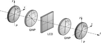 Fig. 2Operation curve provided by the TNLCD in the phase-only configuration. The points correspond to different gray levels sent to the device. The radial coordinate is the fraction of transmitted irradiance, and the polar angle is the phase retardation.  The aberration to be compensated at each pixel was codified by rounding it to the nearest level using a four-level encoding scheme. In this way, the SLM acts as a diffractive element. In the case of an -level phase encoding scheme, the diffraction efficiency in the useful signal present in the first order of diffraction is equal to27: Then, for , we have . The remaining 19% of the incident light is lost in diffraction orders other than those of interest The diffraction efficiency of real SLMs will be somewhat lower, because the fill factor of the elementary cell is smaller than 1. Therefore, an -step phase grating programmed in the direction will act as a 2-D grating with additional binary amplitude modulation in both directions, and hence its diffraction efficiency in the (1,0) diffraction order will be equal to28:where , are the opening ratios in the and directions, respectively, i.e., the pixel’s widths divided by the SLM’s pitch, equal in our case to and . In our device, this limits the first-order useful signal to 26.7% of the incident energy.In our case, the number of phase steps per period was chosen as . Higher allows us to obtain a higher diffraction efficiency. However, in general this number will be limited by two factors: the maximum phase change admitted by the device , and the maximum wavefront slope to be compensated, which is limited by the width of the minimum number of pixels necessary for covering the phase change of , and is equal to , where is the pixel array pitch. 3.Experimental Results3.1.Experimental SetupTo evaluate the compensation performance of this SLM, an aberrated eye was built, consisting of a focal-length lens and a charged-coupled device (CCD), in front of which different kinds of refractive phase plates were located to introduce different amounts and types of aberration. The compensating SLM was positioned very close to the aberrated plate without using any intermediate optical element. A more precise setup could include a relay optical system to project the SLM plane onto the plate plane, but we did not find it necessary for this proof-of-concept experiment, since for eye aberrations of typical magnitude, a small axial separation between the compensating element and the eye pupil does not give rise to a noticeable loss of compensation.29 The whole setup was illuminated with by a expanded beam from an Ar laser, provided with a set of neutral density filters to keep irradiance at a suitable level. The aberrated plates used in this study were manufactured at Universidade de Santiago de Compostela by gray-level photosculpture, a process already used to fabricate phase plates for the compensation of eye aberrations.19 A layer of Microposit™ S-1800 series photoresist was spin-coated onto a soda-lime glass substrate at for , soft baked in a convection oven at for to remove solvent, and exposed to UV radiation through an aberration-encoding grayscale silver halide mask recorded on AGFA APX-25 film. The solubility of the photoresist in an alkaline medium, very low before exposure, increases dramatically in the exposed areas depending on the absorbed dose, and this feature is used to draw the refractive profile by developing the plates in an alkaline solution during a suitable time at the proper levels of concentration and temperature. Once dried, the plate aberrations were measured using a Shack-Hartmann wavefront sensor (at ) and several interferograms of them were taken using a Mach-Zehnder interferometer (at ). The aberration coefficients measured by the wavefront sensor were used to generate a numerical interferogram, which was compared against the experimentally obtained one to check for consistency. Direct inspection of the plate surface using the light transmitted by a single arm of the interferometer under high magnification was also useful to check for any relevant small-scale surface irregularity that could have been produced in the manufacturing process and gone unnoticed in the interferograms or the wavefront sensor reconstructed phase. In all calculations where different wavelengths were involved, the corresponding corrections were made to take into account the wavelength dependence of the refractive index of the photoresist, whose data are available from the manufacturer. Figure 3 shows the actual interferograms of the plates used in this study (first column), the interferograms computed from the wavefront sensor measurements (second column), and the corresponding four-level phase patterns sent to the SLM (third column). The diameter of the optical zone of the plates is 6.4 mm. The optical zone corresponds to the central part of the interferograms, and is framed by a circle and a square, which are photoresist relief fiducial marks used for alignment purposes. The plates correspond to the Zernike coma term (double-index Optical Society of America scheme)30 in the first row, the Zernike (second row), and a typical pattern of a moderately highly aberrated eye (third row). The magnitude of the aberration generated by each plate is peak-to-valley for , p-v for , and p-v for the aberrated eye (all measurements were made at wavelength). Fig. 3First column: actual interferograms of the plates used in this study; second column: interferograms computed from the wavefront sensor measurements; and third column: the corresponding four-level phase patterns sent to the SLM. The diameter of the optical zone of the plates (central part of the interferograms) is . The circle and the square framing the optical zone are fiducial marks used for alignment purposes. The plates correspond to the Zernike coma term (first row) with an aberration of peak-to-valley ; the Zernike term (second row) with p-v ; and a typical pattern of a moderately high aberrated eye (third row) with p-v . 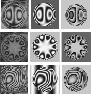 3.2.Aberration CompensationOnce measured, each phase plate was located in front of the lens-CCD setup with the SLM switched off, and an image of the corresponding aberrated point-spread function (PSF) was recorded at the CCD plane. Then, the four-level image of the compensating phase was codified in the SLM, as computed from the Zernike coefficients of the plate given by the wavefront sensor (taking into account the photoresist refractive index correction for working under illumination), and the compensated PSF was recorded. In several cases, an additional PSF was taken, reversing the sign of the SLM phase, to check the effects of doubling the plate aberration instead of correcting it. Finally, the plate was removed from the system, and the PSF produced by the SLM alone was recorded for comparison. Figures 4, 5, 6 show the experimental results corresponding to the compensation of the artificial eye aberrated by the different plates. In Figs. 4a, 5a, 6a, the PSF of the aberrated eye produced by the plate is shown; Figs. 4b, 5b, 6b show the PSF produced by the SLM alone when encoding the compensating phase; Figs. 4c, 5c, 6c show the PSF of the aberrated eye after compensation using the SLM; Figs. 4d, 5d, 6d show the PSF of the aberrated eye when the SLM was codified to produce an aberration of the same magnitude and sign as that of the plate, doubling in this way the original aberration. The resemblance of the PSFs produced by the plate and the SLM alone [(a) and (b) in Figs. 4, 5, 6], aside from the symmetry arising due to the sign reversal, is clearly apparent. As can be seen, the compensated PSF in Figs. 4c, 5c, 6c collapsed in all cases to a size noticeably smaller than that of the original aberrated one. This compensation was somewhat less perfect in the case of the plate with the aberration of an in vivo measured eye (Fig. 6), which included Zernike terms up to the seventh order (35 nontrivial Zernike polynomials), hence being very sensitive to small misalignments of the system, an inherent feature of high-order compensation. The PSFs in Figs. 4d, 5d, 6d, obtained by doubling the artificial eye aberration reversing the sign of the SLM phase, show the general features of the original ones but with a twofold increase of their size. The central spot that can be observed in Fig. 4d corresponds to the residual zeroth-order undiffracted light of the SLM; this small contribution is not apparent in the other figures where the SLM is switched on, since it is superimposed to the much brighter diffracted PSF cores. Note that except for this zeroth-order contribution, no other diffracted light arising from unwanted orders is apparent in the recorded frames. These contributions can only be detected by increasing the gain of the recording CCD well above the saturation level. Fig. 4Compensation of the aberration : (a) aberrated PSF produced by the plate, (b) PSF produced by the SLM alone when encoding the four-level compensating phase, (c) PSF of the aberrated eye after compensation using the SLM, and (d) PSF of the aberrated eye when the SLM encodes an aberration of the same magnitude and sign as that of the plate, doubling in this way the original aberration.  Fig. 5Compensation of the aberration : (a) aberrated PSF produced by the plate, (b) PSF produced by the SLM alone when encoding the four-level compensating phase, (c) PSF of the aberrated eye after compensation using the SLM, and (d) PSF of the aberrated eye when the SLM encodes an aberration of the same magnitude and sign as that of the plate, doubling in this way the original aberration.  Fig. 6Compensation of a complex aberration pattern typical of a human eye: (a) aberrated PSF produced by the plate, (b) PSF produced by the SLM alone when encoding the four-level compensating phase, (c) PSF of the aberrated eye after compensation using the SLM, and (d) PSF of the aberrated eye when the SLM encodes an aberration of the same magnitude and sign as that of the plate, doubling in this way the original aberration.  4.Discussion and ConclusionsWe show that one of the basic limitations of conventional off-the-shelf liquid-crystal SLMs, that is, the reduced dynamic range of the phase retardation that can be introduced at each pixel, can be overcome using a four-level phase encoding scheme, allowing for a theoretical maximum of 81% diffraction efficiency at the desired order, somewhat reduced in practice if the fill factor of the pixel array is smaller than 1. This approach allows us to take advantage of the relatively high spatial resolution of these devices and their inherent features of easy addressability and control, and especially their wide availability and very low cost. High-spatial resolution is a key feature for aberration compensation since, using a modulus phase encoding scheme, the limiting factor is not the maximum peak-to-valley value of the eye aberration to be compensated for, but their maximum local slope. In our case, the maximum slope that can be fully compensated using the SLM in a 1:1 scaling configuration optically conjugated to the eye pupil is at , that is, corresponding to about eight line pairs/mm in the interferogram of the aberration at that wavelength or about 47 wavelengths of prism across a 6-mm-diam pupil. This conservative estimate was made under the assumption that each cycle of prism be sampled by at least four pixels, so that the phase quantization noise inside each pixel (that is, the difference between the actual phase to be compensated for and the phase level set at the corresponding pixel) be smaller than at all locations. Using the same 1:1 scaling configuration, there are more than 180 available pixels across a 6-mm-diam pupil, which according to recent estimations should be enough for achieving diffraction-limited imaging in the compensation of typical eye aberrations.31 As a drawback, the SLM we used has a relatively poor fill factor, so that the achievable Strehl will be lower than the theoretical maximum predicted for 100% fill. The two main limitations of this approach for aberration compensation are common to other SLM devices. First, the SLM needs to be illuminated by a state of completely polarized light, which will amount to an additional loss of 50% of energy if the eye structures of interest depolarize the illuminating beam (although some special-purpose cells have been designed that may handle nonpolarized light32). And second, the efficiency of the four-level phase encoding scheme is, of course, wavelength dependent due to the phase wrapping, the material dispersion of the liquid crystal, and the wavelength dependence of the quarter wave plates, so that its performance is degraded as the illuminating wavelength differs from the design one, hence we had to use relatively narrowband light. A bandwidth of order may be acceptable if zero-order waveplates are used. As an additional limitation, the particular SLM used in our demonstration is able to achieve a phase modulation for wavelengths of or smaller, which hinders its use to compensate aberrations with four-level phase encoding at longer wavelengths. This last limitation may be partially alleviated using a three-level or a binary phase scheme, but only at the cost of dropping the first-order diffraction efficiency to levels of 68.4 or 40.5%, respectively (23.8 or 16.8% when the fill factor of the device’s elementary cell will be taken into account). However, these limitations are balanced by some practical advantages. Off-the-shelf SLMs have easy addressability and the possibility of compensating dynamical aberrations. They are directly compatible with all commonly used software for graphic display, since they are essentially a computer screen. And additionally, they present a particularly attractive feature, which is the combination of a high spatial resolution with a very low cost (which may be about 30 times smaller than that of other special-purpose SLMs of comparable resolution). Taking into account all of these factors, we believe that off-the-shelf SLMs may be an interesting complement to the solutions already available for aberration compensation, and may potentially find a niche in those applications where low cost and easy availability are an issue. Finally, in this work we use a simple open-loop compensation procedure, which does not allow for an easy correction of the effects of small misalignments of the SLM with respect to the phase plates. Eye aberration compensation has been shown to be very sensitive to small transversal misalignments, as well as to in-plane rotations of the correcting element.29, 33 A closed-loop approach, where the residual phase after compensation would be measured and used to drive the SLM with a refined estimate of the phase, would very likely allow even better results. AcknowledgmentsThis work has been supported by the Spanish Ministerio Educación y Ciencia, Grants FIS2004-02404, FIS2005-05020-C03-02, and FEDER, and by the Polish Ministerstwo Nauki i Informatyzacji under Contract Number 4 T07D 003 29 1691/T07/2005/29. ReferencesJ. Hartmann,
“Objektivuntersuchungen,”
Z. Instrumentenkd., 24 1
–21
(1904). 0372-8420 Google Scholar
J. Hartmann,
“Objektivuntersuchungen,”
Z. Instrumentenkd., 24
(3), 34
–47
(1904). 0372-8420 Google Scholar
J. Hartmann,
“Objektivuntersuchungen,”
Z. Instrumentenkd., 24
(7), 98
–117
(1904). 0372-8420 Google Scholar
H. W. Babcock,
“The possibility of compensating astronomical seeing,”
Astron. Soc. Pac., 65
(386), 229
–236
(1953). https://doi.org/10.1086/126606 Google Scholar
M. S. Smirnov,
“Measurement of the wave aberration of the human eye,”
Biofizika, 6 687
–703
(1961). 0006-3029 Google Scholar
A. Roorda and
D. R. Williams,
“The arrangement of the three cone classes in the living human eye,”
Nature (London), 397 520
–522
(1999). https://doi.org/10.1038/17383 0028-0836 Google Scholar
R. V. Shack and
B. C. Platt,
“Production and use of a lenticular Hartmann screen,”
J. Opt. Soc. Am., 61 656
(1971). 0030-3941 Google Scholar
J. Z. Liang,
B. Grimm,
S. Goelz, and
J. F. Bille,
“Objective measurement of wave aberrations of the human eye with the use of a Shack-Hartmann wave-front sensor,”
J. Opt. Soc. Am. A, 11 1949
–1957
(1994). 0740-3232 Google Scholar
R. Navarro and
M. A. Losada,
“Phase transfer and point-spread function of the human eye determined by a new asymmetric double-pass method,”
J. Opt. Soc. Am. A, 12 2385
–2392
(1995). 0740-3232 Google Scholar
R. H. Webb,
C. M. Penney, and
K. P. Thompson,
“Measurement of ocular local wave-front distortion with a spatially resolved refractometer,”
Appl. Opt., 31 3678
–3686
(1992). 0003-6935 Google Scholar
A. W. Dreher,
J. F. Bille, and
R. N. Weinreb,
“Active optical depth resolution improvement of the laser tomographic scanner,”
Appl. Opt., 28 804
–808
(1989). 0003-6935 Google Scholar
J. Z. Liang,
D. R. Williams, and
D. T. Miller,
“Supernormal vision and high resolution retinal imaging through adaptive optics,”
J. Opt. Soc. Am. A, 14 2884
–2892
(1997). 0740-3232 Google Scholar
H. Hofer,
L. Chen,
G. Y. Yoon,
B. Singer,
Y. Yamauchi, and
D. R. Williams,
“Improvement in retinal image quality with dynamic correction of the eye’s aberrations,”
Opt. Express, 8 631
–643
(2001). 1094-4087 Google Scholar
E. J. Fernández,
I Iglesias, and
P. Artal,
“Closed-loop adaptive optics in the human eye,”
Opt. Lett., 26 746
–748
(2001). https://doi.org/10.1038/35071146 0146-9592 Google Scholar
L. Diaz-Santana,
C. Torti,
I. Munro,
P. Gasson, and
C. Dainty,
“Benefit of higher closed-loop bandwidths in ocular adaptive optics,”
Opt. Express, 11 2597
–2605
(2003). 1094-4087 Google Scholar
G. D. Love,
“Wave-front correction and production of Zernike modes with a liquid-crystal spatial light modulator,”
Appl. Opt., 36 1517
–1524
(1997). 0003-6935 Google Scholar
L. N. Thibos and
A. Bradley,
“Use of liquid-crystal adaptive optics to alter the refractive state of the eye,”
Optom. Vision Sci., 74 581
–587
(1997). https://doi.org/10.1097/00006324-199707000-00028 1040-5488 Google Scholar
F. Vargas-Martin,
P. M. Prieto, and
P. Artal,
“Correction of the aberrations in the human eye with a liquid crystal spatial light modulator: limits to performance,”
J. Opt. Soc. Am. A, 15 2552
–2562
(1998). 0740-3232 Google Scholar
T. Shirai,
“Liquid-crystal adaptive optics based on feedback interferometry for high-resolution retinal imaging,”
Appl. Opt., 41 4013
–4023
(2002). 0003-6935 Google Scholar
P. M. Prieto,
E. J. Fernández,
S. Manzanera, and
P. Artal,
“Adaptive optics with a programmable phase modulator: applications in the human eye,”
Opt. Express, 12 4059
–4071
(2004). https://doi.org/10.1364/OPEX.12.004059 1094-4087 Google Scholar
R. Navarro,
E. Moreno-Barriuso,
S. Bará, and
T. Mancebo,
“Phase-plates for wave-aberration compensation in the human eye,”
Opt. Lett., 25 236
–238
(2000). 0146-9592 Google Scholar
S. A. Burns,
S. Marcos,
A. E. Elsner, and
S. Bará,
“Contrast improvement of confocal retinal imaging by use of phase-correcting plates,”
Opt. Lett., 27 400
–402
(2002). 0146-9592 Google Scholar
V. Durán,
J. Lancis,
E. Tajahuerce, and
Z. Jaroszewicz,
“Cell parameter determination of a twisted-nematic liquid crystal display by single-wavelength polarimetry,”
J. Appl. Phys., 97 043101
(2005). https://doi.org/10.1063/1.1846142 0021-8979 Google Scholar
S. T. Tang and
H. S. Kwok,
“ matrix for unitary optical systems,”
J. Opt. Soc. Am. A, 18
(9), 2138
–2145
(2001). 0740-3232 Google Scholar
V. Durán,
J. Lancis,
E. Tajahuerce, and
Z. Jaroszewicz,
“Equivalent retarder-rotator approach to on-state twisted nematic liquid crystal displays,”
J. Appl. Phys., 99 113101
–6
(2006). https://doi.org/10.1063/1.2198929 0021-8979 Google Scholar
N. Konforti,
E. Maron, and
S. T. Wu,
“Phase-only modulation with twisted nematic liquid-crystal spatial light modulators,”
Opt. Lett., 13 251
–253
(1988). 0146-9592 Google Scholar
J. L. Pezzaniti and
R. A. Chipman,
“Phase-only modulation of a twisted nematic liquid-crystal TV by use of the eigenpolarization states,”
Opt. Lett., 18 1567
–1569
(1993). 0146-9592 Google Scholar
I. Moreno,
P. Velásquez,
C. R. Fernández-Pousa,
M. M. Sánchez-López, and
F. Mateos,
“Jones matrix method for predicting and optimizing the optical modulation properties of a liquid-crystal display,”
J. Appl. Phys., 94 3697
–3702
(2003). https://doi.org/10.1063/1.1601688 0021-8979 Google Scholar
H. Dammann,
“Blazed synthetic phase only holograms,”
Optik (Jena), 31 95
–104
(1970). 0030-4026 Google Scholar
Z. Jaroszewicz,
A. Kołodziejczyk,
A. Kowalik, and
R. Restrepo,
“Determination of phase step errors of kinoform gratings from their diffraction efficiencies,”
Opt. Eng., 40
(5), 692
–697
(2001). https://doi.org/10.1117/1.1358296 0091-3286 Google Scholar
S. Bará,
T. Mancebo, and
E. Moreno-Barriuso,
“Positioning tolerances for phase plates compensating aberrations of the human eye,”
Appl. Opt., 39 3413
–3420
(2000). 0003-6935 Google Scholar
L. N. Thibos,
R. A. Applegate,
J. T. Schwiegerling,
R. Webb, VSIA Standards Taskforce Members,
“Standards for reporting the optical aberrations of eyes,”
Vision Science and Its Applications 2000, 232
–244 Optical Society of America, Washington, D.C. (2000). Google Scholar
D. T. Miller,
L. N. Thibos, and
X. Hong,
“Requirements for segmented correctors for diffraction-limited performance in the human eye,”
Opt. Express, 13 275
–289
(2005). https://doi.org/10.1364/OPEX.13.000275 1094-4087 Google Scholar
G. D. Love,
“Liquid-crystal phase modulator for unpolarized light,”
Appl. Opt., 32 2222
–2223
(1993). 0003-6935 Google Scholar
A. Guirao,
D. R. Williams, and
I. G. Cox,
“Effect of rotation and translation on the expected benefit of an ideal method to correct the eye’s higher-order aberrations,”
J. Opt. Soc. Am. A, 18 1003
–1015
(2001). 0740-3232 Google Scholar
|


