1.IntroductionAn optical instrument generates an ideal image if all rays of a (monochromatic) light bundle from a point in the object’s space meet in one single image point. In eyes with visual acuity of 20/20 or better only rays passing the central pupil area will fulfill this condition satisfactorily.1 Other rays, especially those entering the cornea of the eye more peripherally, experience directional deviations which are mostly irregular and asymmetrical. This results in a corresponding enlargement of the beam cross section at the ocular image plane and may reduce visual acuity. The effects of these irregularities on the ocular image are termed image errors or optical aberrations, well known, e.g., as astigmatism, spherical aberration, coma, distortion, etc. These optical errors, except astigmatism, cannot be corrected by means of spherocylindrical spectacle lenses. Contact lenses diminish them only if they are caused by the anterior corneal surface. The ocular optical aberrations are of natural origin or can result from operations in the eye (side effects of eye surgery, intraocular lens implantation) or from ocular diseases (e.g., keratoconus). Both intended (refractive surgery) and unintentional changes (e.g., after cataract surgery) of the spatial configuration of refractive surfaces (radius of curvature, centration) of the eye may increase or decrease as well higher order aberrations. Their clinical measurement is a prerequisite for the correction of these errors with modern photorefractive methods or for the judgment of effects of ocular diseases impairing the optical performance of the eye. At present different objective techniques for the measurement of ocular image errors are known. Walsh et al.;2 proposed a cross cylinder method (the Howland aberroscope technique), a modification of Tscherning’s aberroscope.3 The use of a Hartmann–Shack wave front sensor was reported by Liang et al.;4 Molebny et al.;5 presented a ray scanning method. The measuring system presented is based directly on the original aberroscope of Tscherning.3 It was designed and tested by the authors in clinical routines. In 130 eyes with best corrected visual acuity of 20/20 or better the monochromatic image aberrations were determined to assess the order of magnitude tolerated by the visual system with normal visual acuity.6 In another study 15 eyes of 15 patients were measured before and after photorefractive keratectomy7 and in Ref. 8 initial results of wave front-guided laser in situ keratomileuses (LASIK) were presented using the aberrometer system described. 2.Measuring PrincipleA parallel bundle of light is split into a group of single thin parallel rays by means of a mask with a regular matrix of fine holes. These rays are focused by a low-power lens in front of the eye so that the intraocular focus point is located about 2.5 mm in front of the retina. Therefore, the power of this “aberroscope lens” depends on the mean ocular spherical refraction. In the case of an emmetropic eye the dioptric power of this lens should be in the range from +4 to +5 D. In myopic eyes with a refraction from −6 to −9 D this lens can be omitted. For hyperopic eyes of more than +2 D a lens with a power of more than +5 D is needed. In that way a pattern of light spots is generated onto the retina (Figure 1). The purpose of the aberroscope lens is only to sufficiently enlarge the retinal spot pattern to separate and to identify the single light spots. In an eye with ideal optical performance, free of any monochromatic optical aberrations, this subjectively well recognizable spot pattern has the same regularity as the rays before entering the eye. In practice the retinal light spot pattern is more or less distorted according to the existing ocular optical aberrations. The effect of one’s own ocular optical errors is subjectively visible for the patient and qualitatively describable. Figure 1Optical principle of Tscherning’s aberroscope applied. The two upper rays (dashed lines) represent the ideal case, free of any monochromatic optical aberration. The lower rays illustrate the situation in an eye with aberrations. The light spots on the retina are imaged through a narrow optical channel onto the sensor of a low-light CCD camera by means of indirect ophthalmoscopy.  To assess the distortion of the retinal spot pattern quantitatively measurement of the retinal light spot positions is necessary. The retinal light pattern is imaged onto the sensor of a low-light charge coupled device (CCD) video camera by indirect ophthalmoscopy. The geometrical-optical paraxial channel used has a diameter of about 1 mm within the eye. This optical channel is assumed to be approximately free of higher-order aberrations. The coordinates of the geometric centers of all imaged retinal light spots are determined by means of image processing PC software. The ideal pattern coordinates under aberration free conditions are calculated from parameters of Gullstrand’s simplified eye model,9 the length of which is assessed by the mean spherical refraction measured with an autorefractometer. Thus for each light spot the displacement from its ideal position can be computed. This matrix of two-dimensional deviations represents the directional aberrations of the measuring rays from their ideal intraocular course (Figure 2). Because these measuring rays are related to determined positions on the cornea, or on the ocular image-side principal plane respectively, it is possible to reconstruct the deviation of the real intraocular wave front from its ideal desirable spherical shape with these data. The wave front aberration is expressed as the sum of Zernike polynomials up to sixth order. The coefficients of these polynomials describe mathematically the quantity of higher-order optical errors within the eye. Some of the Zernike coefficients are correlated to conventionally known image errors like astigmatism, spherical aberration, or coma. 3.ConstructionThe light source for the measuring rays is a green (532 nm) diode-pumped solid state laser (model LCM-LL-11 qps, Laser 2000 GmbH, Wessling, Germany) with a beam diameter of about 2 mm and an output power of 10 mW (Figure 3). The measuring light is controlled by an electromechanical shutter with an opening time of about 60 ms. The laser beam is enlarged to a diameter of about 25 mm by means of a beam expander (a Keplerian telescope) with a spatial filter (diameter of 15 μm). Figure 4 (left) shows the configuration of the dot pattern mask (photographic film) that produces the system of test rays. The diameter of a single ray is about 0.3 mm. These rays are focused by a changeable aberroscope lens. The three lenses used have refractive powers of +4, +2.5, and +1 D depending on the mean ocular spherical refraction (allowable range from +2 to −6 D). For eyes with myopia from −6 to −12 D this lens was omitted. The dot pattern masks are also changeable. They differ only in the dot spacing. For each aberroscope lens there is a mask, ensuring spacing of the measuring rays on the cornea’s front side of 0.6 mm in each case. Figure 3Schematic of optical components of the ocular optical aberrometer. For details see the text.  Figure 4Left: Dot pattern mask. The hole diameter is 0.33 mm. For an aberroscope lens of +4 D (for emmetropic eyes) the hole spacing constant amounts to 0.805 mm. Right: Examples of processed and inverted images of retinal light spot. The effects of ocular aberrations are clearly exhibited.  The correct position of the eye during exposure of the retinal spot pattern is controlled by a near infrared (NIR) light system. The eye is illuminated by two NIR-light emitting diodes (LEDs) (950 nm) and by the vertical narrow light bundle of a slit lamp (Carl Zeiss Jena) with a NIR filter. The eye is monitored by a mirror and a CCD video camera through the aberroscope lens and the exit aperture of the aberroscope. The correct eye position is adjusted if the NIR slit bundle and the exit aperture are centered on the pupil of the eye on the monitor. The aberroscope is mounted on a cross-slide stage and thus is adjustable in any position. The patient’s head is fixed by a chin rest and a forehead bar. The retinal spot pattern, of about 1×1 mm 2 in extension is imaged by the ophthalmoscope lens (f=40 mm) and the camera lens (f=30 mm) onto the sensor array (12.8 mm×9.6 mm) of a low-light CCD video camera (type LH 750 LL, Lheritier S.A., Cergy Pontoise, France). The light sensitivity of the camera amounts to about 2×10⁻⁴ lux. The camera position is adjustable in order to consider the various positions of the intermediate image of the retinal spot pattern, depending on the ocular refraction. No ocular optical corrections were used. A small diaphragm (diameter 1.0 mm) at the camera lens is imaged by the ophthalmoscope lens onto the cornea (input aperture diameter 1.08 mm) and ensures that only rays through this narrow ocular paraxial space contribute to the image. As a rule, the pupils were dilated to 6 mm or more. Figure 4 (right) shows two examples of processed and inverted retinal light spot patterns. 4.Computation ProcedureAs mentioned above the result of the image-grabbing procedure is a two-dimensional matrix with the deviations of each single measuring ray in the x and y directions. From these data derivations of the wave front aberration at each corresponding corneal position are calculated using the parameters of Gullstrand’s simplified eye model9 and corrected for the effect of the aberroscope lens used. The resulting two matrices specify derivative surfaces of the wave front aberration sampled at regular intervals. Neglecting their derivative nature we can consider the problem of fitting these with polynomial expressions in x and y. Evidently what is needed are polynomials which are orthogonal over the pupil. Therefore the well-known Zernike polynomials10 are used: where W(x,y) is the wave front aberration, Zi(x,y) is the ith Zernike polynomial (i=0,…,n), and Ci is the ith weighting factor (Zernike coefficient). Because only the derivatives of W(x,y) are known, Eq. (1) must be changed to where ∂W(xk,yk)/∂x and ∂W(xk,yk)/∂y are the derivations of the wave front aberration in the x and y directions at the corneal position xk,yk calculated from the retinal images, ∂Zi(xk,yk)/∂x and ∂Zi(xk,yk)/∂y are the derivations of the ith Zernike polynomial at these positions, and k is an index for each measuring ray (k=1,…,m). So two equation systems have to be solved: where indices x and y stand for the derivative along x and y. From these systems the Zernike coefficients can be calculated by means of the two-dimensional least-square approximation. Because of the possible numerical instability of the solution the singular-value decomposition (SVD)11 is used to solve these mathematical problems.To get a solution the condition m⩾n+1 must be satisfied but to improve the accuracy of the result this condition must be changed to m⩾2(n+1). The number of measuring rays depends on the size of the pupil of the eye investigated (for a 6 mm pupil 68 rays can pass the eye). Therefore it is necessary to choose a proper number of Zernike polynomials to get a high accuracy of the calculated coefficients. But the number of Zernike polynomials used (n+1) not only depends on the number of retinal spots (m) because these polynomials are only closed on certain orders. Table 1 shows the n values used depending on the number of retinal spots. Table 1
Thus for a dilated pupil it is possible to perform a Zernike expansion with eighth order polynomials (n+1=45). The minimal pupil size for a calculation of wave front aberration is 3.5 mm. The result of the computation is a vector of (n+1) Zernike coefficients, usually expressed in μm or in multiples of the wavelength used. By means of this vector it is possible to reconstruct the wave front aberration [Eq. (1)]. The result is illustrated as a height map of the measured wave front aberration over the pupil investigated (see the example in Figure 5). It looks similar to a corneal topographic map of the eye investigated but it includes optical errors of the whole optical system of the eye. Figure 5Example of measured wave front aberration. Left: Myopic eye with all optical errors included. Right: Same eye after subtracting the spherocylindrical portion. 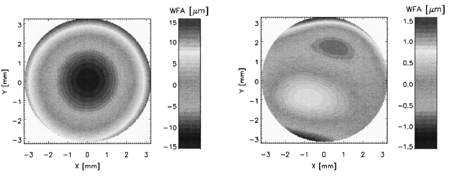 As the rule, 27 Zernike coefficients were determined to describe the individual intraocular wave front aberration. From some of the Zernike coefficients it is possible to recalculate the spherical and cylindrical refraction and the angle of astigmatism of the eyes investigated: where R is the radius of the pupil and C3, C4, and C5 are the Zernike coefficients of second order, which describes the spherocylindrical portion of the wave front aberration. If the calculated angle is negative, 180 ° must be added to fit the definitions of the astigmatism. These parameters are only for a rough comparison with conventionally assessed values of eye refraction.In addition the Zernike coefficients can be used to estimate the mean-square deviation of the wave front aberration from a perfect spherical surface. The root of this deviation [the root mean square value (rms)] can be computed by where Ci are the Zernike coefficients and Fi are weighting factors for each optical error. If the condition rms⩽λ/14 is fulfilled then the resolution of the optical system is only diffraction limited, and the system is aberration free (the Marachel criterion10). In our study6 for 130 human eyes we found not one aberration free at pupil size ⩾5 mm.The accuracy and reproducibility of the measurement system described was tested with a nearly aberration-free photographic lens and with cylindrical lenses. It was found that the absolute error of the wave front aberration was only 150 nm, which is approximately one fourth that of the wavelength used. By rotation of the cylindrical lens in front of the device, we found absolute accuracy for the calculated angel of astigmatism of 1 ° with reproducibility of only ±0.2 °. The absolute error of the calculated power of the cylindrical lens was 0.15±0.05 D. All of the described computations were performed by means of a standard PC [Pentium II, 333 MHz with 128 MByte random access memory (RAM)]. We used self-designed software to grab the images and to perform image processing and calculations. 5.CommentsThe optical aberrometer for human eyes presented does not provide exact measurements because of some specific reasons. The assumption of an approximately aberration-free paraxial ocular channel with a diameter of about 1 mm is not given in every individual case. The optical performance of this channel is not known and can falsify the measurements, especially in inhomogeneities of refractive surfaces along it (e.g., at the center of the outer surface of the cornea). Furthermore, the image quality of the retinal light spots depends on the optical transparency of intraocular media that are passed by the measuring and the imaging rays. Some opacities of the ocular lens or the vitreous body can considerably diminish the intensity of these rays that spots cannot be detected by the image processing program. Missing spots of the pattern image increase the error in assessment of the Zernike coefficients. The use of light with wavelength in the red spectral region penetrating better opaque media could possibly reduce some of these difficulties. The technique presented allows only the measurement of eyes with astigmatism of less than 3–4 D. In eyes with greater astigmatic differences the retinal light spot separations in one of the main axes is so reduced that clear identification of the spots is not possible. Finally, the exact position of the eye with regard to the measuring ray system plays an important role. Small decentrations can significantly influence the results. To overcome this problem efficient image processing software of the NIR pupil image is necessary. The record of the retinal spot pattern (during the shutter opening) should be possible only if the pupil is correctly positioned in relation to the slit lamp bundle and the exit aperture of the device. Nevertheless, the measurement results and practical experience showed that the ocular optical aberrometer presented is a useful device applicable under clinical conditions. AcknowledgmentsThis work was supported by the Deutsche Forschungsgemeinschaft and by the Brunenbusch–Stein-Stiftung. REFERENCES
M. C. W. Charman
,
“Wavefront aberration of the eye: A review,”
Optom. Vision Sci. , 68 574
–583
(1991). Google Scholar
T. Walsh
,
W. N. Charman
, and
H. C. Howland
,
“Objective technique for the determination of monochromatic aberrations of the human eye,”
J. Opt. Soc. Am. A , 1 987
–992
(1984). Google Scholar
M. Tscherning
,
“Die monochromatischen aberrationen des menschlichen auges,”
Z. Psychol. Physiol. Sinne , 6 456
–471
(1894). Google Scholar
J. Liang
,
B. Grimm
,
S. Goelz
, and
J. F. Bille
,
“Objective measurement of wave aberrations of the human eye with the use of a Hartmann–Shack wave-front sensor,”
J. Opt. Soc. Am. A , 11 1949
–1957
(1994). Google Scholar
V. V. Molebny
,
J. G. Pallikaris
,
L. P. Naoumidis
,
I. H. Chyzh
,
S. V. Molebny
, and
V. M. Sokurenko
,
“Retina ray-tracing technique for eye-refraction mapping,”
Proc. SPIE , 2971 175
–183
(1997). Google Scholar
M. Kaemmerer
,
M. Mrochen
,
P. Mierdel
,
H.-E. Krinke
, and
T. Seiler
,
“Clinical experience with the Tscherning aberrometer,”
J. Refract. Surg. , 16 S584
–S587
(2000). Google Scholar
T. Seiler
,
M. Kaemmerer
,
P. Mierdel
, and
H.-E. Krinke
,
“Ocular optical aberrations after photorefractive keratectomy for myopia and myopic astigmatism,”
Arch. Ophthalmol. (Chicago) , 118 17
–21
(2000). Google Scholar
M. Mrochen
,
M. Kaemmerer
, and
T. Seiler
,
“Wavefront-guided laser in situ keratomileusis: Early results in three eyes,”
J. Refract. Surg. , 16 116
–121
(2000). Google Scholar
|
||||||||||||||||||||


CITATIONS
Cited by 29 scholarly publications.
Eye
Wavefronts
Monochromatic aberrations
Cameras
Refraction
CCD cameras
Optical aberrations


