1.IntroductionThe human retinal nerve fiber layer (RNFL) is formed by the unmyelinated axons of retinal ganglion cells gathered into bundles that lie just under the retinal surface. Because the RNFL is damaged in glaucoma and in other optic nerve diseases, RNFL assessment by various optical methods has proven to be valuable for clinical diagnosis and management. One such assessment method, scanning laser polarimetry (SLP), incorporates ellipsometry into a confocal scanning laser ophthalmoscope in order to detect the birefringence of the peripapillary RNFL.1 2 Although corneal birefringence can complicate SLP measurements,3 4 SLP is attractive because it provides rapid assessment, a visual image of the RNFL, and the potential for reproducible, objective measures of RNFL loss. Detailed understanding of SLP comes from an analytical model of the measurement,4 but establishing a relation between RNFL retardance as used in the model and actual RNFL thickness requires an accurate value for RNFL birefringence. There currently exists only limited knowledge of this value and of the mechanism responsible for RNFL birefringence. The only published value for RNFL birefringence comes from Weinreb et al.;,5 who measured the retardance at many locations in two fixed macaque eyes with the anterior segments removed and compared it with the RNFL thickness determined by histology. They found good correlation ( r=0.83 ) with 1° of retardance at 514 nm corresponding to 7.4 μm of RNFL thickness. Their measurement, however, suffers from at least three uncertainties that limit its usefulness. First, it was obtained in fixed tissue, but the effects of tissue fixation on the birefringent structures of the RNFL are unknown. Second, the value is at 514 nm, SLP operates in the near infrared (780 nm), and the wavelength dependence of RNFL birefringence is unknown (see below). Third, the retardance measurements were made in reflection. If the measurement beam was reflected at a layer deep to the retina, as is usually assumed, the retardance can be attributed to a double pass of the RNFL to yield a birefringence of 0.10 nm/μm. If, however, reflection from the RNFL itself contributed to the measurement, the retardance could represent as little as a single pass of the RNFL,6 or a birefringence of 0.19 nm/μm. (Birefringence is a dimensionless number and is often expressed as such, e.g., 1.0×10⁻⁴ and 1.9×10⁻⁴ in the preceding cases. In this paper, however, we use units of nm/μm in order to acknowledge explicitly the sought after relation between retardance and thickness.) The RNFL is generally assumed to exhibit form birefringence, i.e., birefringence due to an array of parallel cylinders in a medium of different refractive indexes. Such an array behaves as a uniaxial crystal with its optic axis parallel to the cylinders’ axes.7 If the cylinder thickness is much less than the wavelength of light, the birefringence of the array depends only on the volume fractions and relative refractive indices of the cylinders and the medium.7 8 Spectral variation of form birefringence should depend, therefore, only on the dispersion of the constituents of the array. The major constituents of cylindrical axonal structures (protein in microtubules and lipid in axonal membranes) do not absorb appreciably at visible and near-infrared wavelengths and their refractive indices vary slowly in this region. The aqueous medium likewise has low dispersion. Thus, if RNFL birefringence arises from form birefringence of thin cylinders, it should not vary with the wavelength. Light scattering spectra of the RNFL indicate, however, that both thin and thick cylinders contribute to the RNFL reflectance.9 Hemenger has shown that an array of thick cylinders with low relative refractive indices can produce form birefringence that depends on the spatial correlation of the array and that decreases to zero at short wavelengths.10 Thus, if RNFL birefringence has such a thick cylinder component, it may vary with the wavelength. In order to clarify the uncertainties outlined above, we used transmission measurements of isolated rat retinas to obtain single-pass values for RNFL retardance at several wavelengths in the visible and near infrared. In addition, we measured the retardance of the same nerve fiber bundles before and after brief glutaraldehyde fixation. Finally, we determined the thickness of the bundles to obtain the birefringence of living and fixed RNFLs. 2.Methods and Materials2.1.Multispectral Imaging MicropolarimeterA multispectral imaging micropolarimeter was designed to measure the retardance of the RNFL (Figure 1). Light from a tungsten–halogen lamp followed by an interference filter (10 nm full width at half maximum) provided monochromatic illumination to an integrating sphere (IS). Lens L 1 ( fl=56 mm) collimated the beam incident onto a polarizer (P). Use of an IS assured that the output intensity of P varied less than 0.2 as P rotated 360°. Lens L 2 [ fl=40.5 mm, numerical aperture (NA)=0.13] focused the exit aperture of the IS onto a specimen in a chamber with flat entrance and exit windows. The irradiance at the specimen’s plane varied from 0.05 W/m 2 at 440 nm to 6 W/m 2 in the near infrared. Lens L 3 ( fl =60 mm, NA=0.07) focused the specimen onto a cooled charge-coupled device (CCD) (Roper Scientific, Tucson, AZ) that provided a pixel size of about 4 μm on a specimen in an aqueous medium (approximate magnification=5.8). Although the lenses were nominally achromatic, the wide spectral range required small changes of the camera position (moving the L 3 and CCD together within a 0.5 mm range) to adjust the focus at each wavelength. The responses were black level corrected to compensate for the dark current and bias level of the CCD. A liquid crystal linear retarder (C′) (Meadowlark Optics, Inc., Frederick, CO) followed by a linear analyzer (A) were used to measure the output Stokes vector of the specimen. Both P and A were Glan–Taylor polarizing prisms (Melles Griot Inc., Irvine, CA). The azimuth and retardance of C′ were set to (0°, 90°), (0°, 200°), (22.5°, 207°), and (−22.5°, 207°) and the azimuth of A was fixed at 45°. Each setting of C′A was characterized by a 1×4 measurement vector D; the four settings together were characterized by a 4×4 measurement matrix (D) with each row corresponding to one D. These C′A settings were chosen to maximize the determinant of D within mechanical constraints on the azimuth of C′.11 Figure 1Schematic diagram of the multispectral imaging micropolarimeter used in transmission mode. LS—light source; IF—interference filter; IS—integrating sphere; P—linear polarizer; SP—specimen; CB—chamber; L 1 , L 2 , and L 3 —lenses; C′—linear retarder; A—linear analyzer; CCD—charge-coupled device. 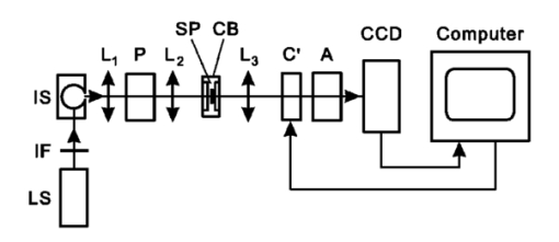 A Stokes vector (S), a 4×1 vector describing the polarization state of a light beam, can be measured by C′A as where D −1 is the inverse of the measurement matrix of C′A and R is a 4×1 response vector corresponding to the four settings of C′A.12The micropolarimeter was used to measure a linear retarder as follows. The Mueller matrix of a linear retarder M rtd is a function of its azimuth ρ and retardance δ .13 With incident light of known polarization state S in , the output Stokes vector of a linear retarder was where the factor K was added to account for losses of intensity in transmission. The calibrated C′A was used to measure S by Eq. (1). If S in was not an eigenvector of the retarder,14 Eq. (2) includes four equations in the three unknowns K, ρ , and δ . In most cases the system of equations in Eq. (2) was further overdetermined by using more than one S in ; if N known polarization states were used, then S in and S became 4×N matrices. Equation (2) was solved for K, ρ , and δ by a least-squares fitting procedure implemented in Matlab (The MathWorks, Inc., Natick, MA).2.2.Polarimeter CalibrationCalibration of D was required because the azimuths of C′ and A could not be set perfectly and the retardance of C′ varied across its aperture. Because C′A had a low extinction ratio (∼3×10⁻⁴ ), C′ and A were assumed to have no depolarization. On this assumption D had the normalized form (1 d2 d3 d4) with d4 satisfying Elements d2 and d3 were calibrated by using a single linear polarizer P to provide an incident Stokes vector, where p is the azimuth of P and superscript T indicates a transposed vector. Without the specimen, the measured response wasSix P positions 60° apart were used to overdetermine d2 and d3 for each setting of C′A. The magnitude of d4 was calculated from Eq. (3) and the sign was determined by the sign of sin(δ) with δ the retardance of C′.15 The calibrated measurement matrix D was validated at 520 nm by measuring a quarter-wave retarder with a specified retardance of 131.6 nm. The retarder was oriented 45°. The retardances averaged across an image [mean ± standard deviation (SD)] were 131.1±0.16, 131.0±0.22, and 131.2±0.20 nm with three D’s calibrated at different times. The azimuths were 44.44°±0.67°, 44.40°±0.09°, and 44.30°±0.06°, respectively. The effect of the chamber windows was estimated by measuring the extinction ratio (ER) of the chamber at various chamber azimuths. The chamber filled with Ringer solution was placed in the micropolarimeter, shown in Figure 1 and C′ was set parallel to A with a retardance of zero. Maximum (I max ) and minimum ( I min ) responses were measured at 520 nm with P rotated to be parallel to and crossed with A, respectively. The largest ER (= I min /I max ) was about 6×10⁻⁴ . This was only slightly higher than the ER without the chamber (∼3×10⁻⁴ ) and was too small to influence the measurements. 2.3.MaterialsRat retinas were chosen for the experiments because, as in humans, the axons in rat RNFLs are unmyelinated and because rat nerve fiber bundles are separated by gaps that allow correction for the polarization properties of the retina (see Sec. 2.4). The eye of an anesthetized rat was removed and the animal was euthanized. A 5 mm diam piece of the posterior globe that included the optic nerve was excised with a razor blade and small scissors and placed in a dish of warm (33–35 °C) oxygenated Ringer solution. The retina was dissected free of the retinal pigment epithelium and choroid with a fine glass probe and then stretched across a slit in a black membrane filter (0.8 μm pore; Millipore, Bedford, MA) with the photoreceptor side against the membrane.16 The mounted retina was placed in the specimen chamber, which was perfused with oxygenated Ringer solution at 35–37 °C in order to maintain the tissue in a living state. Approximately 10 min elapsed from the time the eye was removed until the retina was mounted and ready for measurements. The isolated living retina appeared nearly transparent and could remain stable for at least 2 h. Retardance measurements of the living retina took about 20 min. The chamber was then perfused with phosphate-buffered 3 glutaraldehyde at room temperature for 20 min, rinsed with the Ringer solution, and the retardance measurements were repeated. Thus, the same bundles were analyzed for each condition. The nerve fiber bundles measured were about 1.5 mm from the optic nerve head. 2.4.Measurement of the Linear Retardance of the RNFLThe RNFL in transmission was modeled as a linear retarder. To measure the retardance of the RNFL, polarizer P provided linearly polarized incident light and illuminated the retina with the vitreous side facing the CCD, that is, the beam first passed through the retina and then the RNFL (Figure 2). The nerve fiber bundles were oriented approximately vertically or at 45°. For each P position images were taken with the four settings of C′A described above. Rectangular measurement areas were chosen both on bundles and on nearby gaps between bundles. The area per bundle ranged from 13 to 56 pixels in the bundles (mean=27 pixels) and from 14 to 245 pixels in the gaps around the bundles (mean=62 pixels). The responses averaged over the pixels in each area were used to calculate the Stokes vector of the area. Figure 2Light path for RNFL measurements in transmission mode. Sb and Sg are the output Stokes vectors for areas with and without bundles, Sp is the linearly polarized incident Stokes vector, M b and M g are the Mueller matrices for the bundles and retina, respectively, and K is a factor to account for intensity variations between gap and bundle areas. 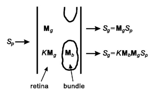 The retardance and azimuth of the RNFL were derived from the measured Stokes vectors, illustrated in Figure 2. The polarization effects of the retina underlying the bundles were estimated by Sg, the average of the Stokes vectors measured in gap areas. By assuming that Sg was also the Stokes vector incident on the bundles, the output Stokes vectors for the retina and bundle areas were expressed as and where Sp is the Stokes vector generated by P, K is a factor to account for spatial variation in intensity, and M g and M b are the Mueller matrices for gap and bundle areas, respectively. The RNFL was assumed to be a linear retarder, i.e., M b=M b(ρ,δ) was assumed to have the form of a linear retarder,13 and Eq. (7) was solved for ρ and δ in the same way as Eq. (2). Two P positions at 45° and 90° generated two sets of Sb and Sg.2.5.Histologic Measurements of the RNFL ThicknessAfter retardance measurements a small piece of the fixed retina containing the measured nerve fiber bundles was cut out with a razor blade, postfixed with osmium, dehydrated, and embedded in Spurr’s media for sectioning. Sections of 1–1.5 μm thickness were usually cut between the areas measured optically and the optic nerve head with 0.25±0.18 mm (mean±SD) between the sections and the areas. Nerve fiber bundles were cut into cross sections and stained with Richardson’s stain. Photomicrographs of the retina were obtained with phase contrast. The bundles measured by polarimetry were identified by matching the distances between the bundles and the blood vessels in the micrograph and in the polarimetry image. The thickness of each bundle was measured on a line perpendicular to the retinal surface that passed through the center of the bundle. 3.ResultsAlthough the isolated retinas were transparent, the birefringent nerve fiber bundles of the RNFL were observable under conditions where the incident polarization state was nearly extinguished by C′A. An example is shown in Figure 3, where P was 45° and C′ was (0°, 200°), a setting that approximated a half-wave plate and thus rotated the polarization so that it was perpendicular to A. Because they were birefringent, the vertical bundles were not extinguished as deeply as the gaps and appeared as bright bands against the retinal background. Auxiliary reflectance images obtained with both white light and subsequent histology confirmed that the bright bands were nerve fiber bundles. Blood vessels were also visible at short wavelengths due to strong absorption by residual red blood cells. Extinction images similar to that in Figure 3 were used in each experiment to select the areas from which birefringence was determined. Figure 3Fixed rat retina viewed with the polarimeter set near extinction. The image is at 440 nm. Nerve fiber bundles (black arrows) appear as bright bands and are separated by gaps where only the retina is visible. Blood vessels (white arrows) containing red blood cells appear black due to strong absorption by hemoglobin. Image size: 640 μm wide×292 μm high. 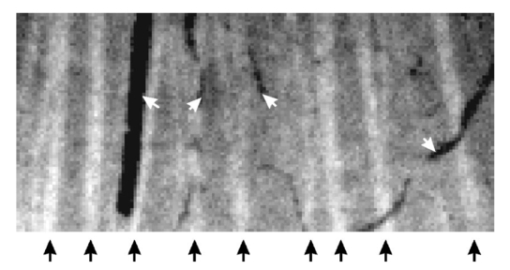 Brief glutaraldehyde fixation did not appreciably change the appearance of the retina. Figure 4 displays at higher magnification a retina before and after 20 min of fixation. The major observable difference between the two images is that the living tissue [Figure 4(a)] appears to have a smoother texture than the fixed tissue [Figure 4(b)]. This blurring may have been due to small retinal movement caused by the circulating perfusion fluid and to dynamically changing components within living bundles.16 Figure 4Images at 440 nm that show two nerve fiber bundles (black arrows) before (a) and after (b) glutaraldehyde fixation. White arrows: blood vessels running across the bundles. Image size: 132 μm wide ×132 μm high. Image exposure: 8 s. 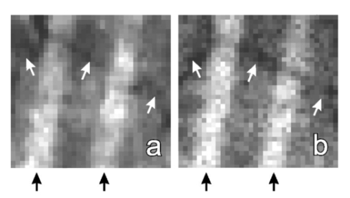 The retardance and azimuth of living and fixed rat RNFLs were measured at widely spaced wavelengths in the visible (440, 520, 600, and 700 nm) and at more closely spaced wavelengths in the near infrared (740, 780, and 830 nm), the wavelength region used by SLP and other diagnostic technologies. Figure 5(a) demonstrates the importance of correcting for the polarization properties of the retina (Figure 2); the estimated retardances of two areas on one bundle are shown. The white arrows in Figure 5(a) are the retardances derived from M=M b M g by assuming input Sp and M a linear retarder. The direction of the arrow (the retarder’s slow axis) does not line up with the bundle as expected. The black arrows are bundle retardances derived from M b with input Sg, the average of 6 areas (a total of 42 pixels) in the gaps on either side of the bundle (areas not shown). The corrected retarders line up with the bundle. Figure 5(b) provides another example that shows the corrected retardances and slow axes of two areas on another bundle and in nine gap areas. The black arrows are bundle retardances derived from M b using as input the averaged Sg of the gap areas. The white arrows in the gaps show the variation of residual retardances after correction and were derived from the M g obtained from each gap area individually by assuming as input the averaged Sg. Figure 5Estimated retardances (arrow length) and slow axes (arrow direction) of bundle and gap areas. The significance of the arrows is explained in the text. Each arrow starts in the center of the area measured. Nerve fiber bundles appear as brighter bands. Calibration bar: 1 nm retardance. The images are at 440 nm. Image size: (a) 222 μm wide×199 μm high; (b) 187 μm wide×177 μm high. 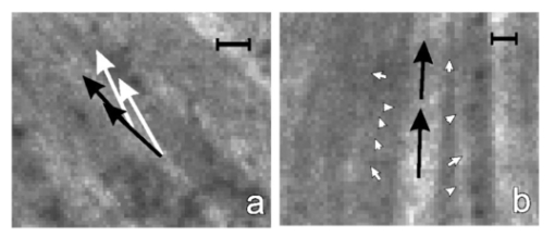 Thirty-seven bundles of eight retinas were investigated. The mean retardance across the bundles was calculated for each wavelength (Table 1). These means are consistent with the hypothesis that the retardance was constant across wavelength from 440 to 830 nm for both living and fixed retinas. To provide a global value for retardance that could be used to determine birefringence, the retardances were averaged across the wavelength (last row of Table 1). The retardance of fixed retinas was 17 lower than that of living retinas, a statistically significant amount (p<0.01). Table 1
Histologically the nerve fiber bundles measured by polarimetry were fairly similar in thickness. This was due in part to a systematic selection of wider, brighter bundles in the images; smaller bundles were not wide enough to place measurement areas that fell completely within the margins of the bundle. The mean thickness of the 37 bundles was 13.9±0.44 μm [mean±standard error (SEM)]. The birefringence of the bundles was calculated by dividing the mean retardance by the mean thickness to give values for living and fixed RNFLs of 0.23 and 0.19 nm/μm, respectively, with an uncertainty of 0.01 nm/μm for each.17 4.DiscussionPrevious studies using reflected light have demonstrated that the RNFL behaves like a linear retarder with its slow axis parallel to the nerve fiber bundles.5 18 This study used isolated rat retinas and transmitted light to confirm this behavior. RNFL birefringence was also demonstrated qualitatively; when retinas were viewed in transmission with polarization states set near extinction (Figures 3 4 5), birefringent nerve fiber bundles appeared bright against a darker retinal background. The retardance of the RNFL was approximately constant from 440 to 830 nm, which suggests that only one mechanism underlies RNFL birefringence. The most likely mechanism is form birefringence due to thin cylindrical structures; the lack of wavelength dependence suggests that a thick cylinder mechanism such as that proposed by Hemenger10 may not contribute. The wavelength independence also justifies extrapolation of the RNFL birefringence measurements made at 514 nm by Weinreb et al.;5 to studies of SLP at 780 nm. The data here provide precise and fairly accurate values for RNFL birefringence in both living and fixed mammalian tissue. Measurements from 37 bundles in 8 retinas were averaged to produce precise values of average retardance and the conclusions about wavelength independence and effect of fixation depend only on their precision. In addition to being precise, we also believe the retardance values to be accurate, because the micropolarimeter calibration depended only on the accuracy of the angular setting of a polarizer and the calibration was validated with measurements of a known retarder. The thickness measurements were individually precise, as was the average across the 37 bundles. Two unknowns, however, limit the accuracy of the average thickness. The first is tissue shrinkage during preparation for histology (perhaps 10) that would cause an underestimate of bundle thickness and an overestimate of birefringence. The second is that the histologic section from each retina was usually closer to the optic nerve head than the areas where retardance was measured. Although the RNFL appeared fairly uniform in the region studied, thinning of the RNFL with distance from the nerve head could have caused an overestimate of the thickness and an underestimate of birefringence. Because these two unknowns worked against each other, we do not believe that the birefringence values reported here are in error by more than 10. These birefringence values must be generalized with caution, however; they were obtained from a limited area (bundles near the optic nerve head) in a single species (rat). Not only could birefringence vary among species, it could also vary between retinal regions. For example, in primate retina the proportion of small axons is highest in papillomacular nerve fiber bundles, lower in arcuate bundles, and much lower in bundles nasal to the optic disk.19 Such structural variation could give rise to variation in form birefringence. The RNFL retained birefringence following glutaraldehyde fixation (Figure 4 and Table 1), although retardance was reduced by about 17 from its value in living tissue. This validates the use of fixed tissue for research on RNFL birefringence5 and suggests that glutaraldehyde fixation does not appreciably alter the geometry or relative refractive indices of the cellular structures that cause the birefringence. Note that the duration of fixation used here (20 min) was shorter than that typically used for histologic fixation and the effects of longer duration were not studied. Investigations with fixed tissue should specify the duration of fixation in order to clarify this issue. The birefringence of fixed RNFL found here (0.19 nm/μm) may be as much as double that found by Weinreb et al.;,5 but several differences between the two studies must still be resolved. First, the eyes measured by Weinreb et al.; were stored in fixative for an unspecified duration before testing (but presumably for much longer than 20 min). Second, the values in the two studies were obtained in different species (macaque and rat) and, although substantial differences in subcellular organelles (e.g., densities of microtubules and axonal membranes8) would be surprising, quantitative electron microscopy is required to determine the similarity of the RNFLs in the two species. Third, the measurements reported here were made in transmission mode and represent a single pass of the measuring beam through the RNFL. The measurements of Weinreb et al.; were made in reflection mode; in reflection mode the effective RNFL thickness depends on the location of the polarization-preserving reflector that returns the measuring beam to the ellipsometer. On the usual assumption of a reflector behind the retina, the measuring beam makes a double pass of the RNFL and the birefringence found by Weinreb et al.; is 0.10 nm/μm, or one half the value found here. Weinreb et al.; recognized that the beam may not have completely penetrated the RNFL, but they did not identify the reflector involved.5 Theoretical calculation shows that the RNFL itself has the properties necessary to be the polarization-preserving reflector,6 in which case the measurement could have been equivalent to single pass with a birefringence the same as that found here. Resolving the above differences between studies and establishing the correct value for the birefringence of the human RNFL is essential for a complete understanding of SLP. REFERENCES
A. W. Dreher
and
K. Reiter
,
“Scanning laser polarimetry of the retinal nerve fiber layer,”
Proc. SPIE , 1746 34
–41
(1992). Google Scholar
A. W. Dreher
and
K. Reiter
,
“Retinal laser ellipsometry: A new method for measuring the retinal nerve fiber layer thickness distribution?,”
Clin. Vision Sci. , 7
(6), 481
–488
(1992). Google Scholar
D. S. Greenfield
,
R. W. Knighton
, and
X.-R. Huang
,
“Effect of corneal polarization axis upon retinal nerve fiber layer thickness assessments using scanning laser polarimetry,”
Am. J. Ophthalmol. , 129
(6), 715
–722
(2000). Google Scholar
R. W. Knighton
,
X.-R. Huang
, and
D. S. Greenfield
,
“Analytical model of scanning laser polarimetry for retinal nerve fiber layer assessment,”
Invest. Ophthal. Visual Sci. , 43 383
–392
(2002). Google Scholar
R. N. Weinreb
,
A. W. Dreher
,
A. Coleman
,
H. Quigley
,
B. Shaw
, and
K. Reiter
,
“Histopathologic validation of Fourier-ellipsometry measurements of retinal nerve fiber layer thickness,”
Arch. Opthalmol. , 108
(4), 557
–560
(1990). Google Scholar
X.-R. Huang
and
R. W. Knighton
,
“Is the retinal nerve fiber layer the polarization-preserving reflector in scanning laser polarimetry?,”
Invest. Ophthalmol. Visual Sci. , 41
(4), S92
(2000). Google Scholar
Q. Zhou
and
R. W. Knighton
,
“Light scattering and form birefringence of parallel cylindrical arrays that represent cellular organelles of the retinal nerve fiber layer,”
Appl. Opt. , 36
(10), 2273
–2285
(1997). Google Scholar
R. W. Knighton
and
X.-R. Huang
,
“Directional and spectral reflectance of the rat retinal nerve fiber layer,”
Invest. Ophthalmol. Visual Sci. , 40
(3), 639
–647
(1999). Google Scholar
R. P. Hemenger
,
“Birefringence of a medium of tenuous parallel cylinders,”
Appl. Opt. , 28
(18), 4030
–4034
(1989). Google Scholar
R. M. A. Azzam
,
I. M. Elminyawi
, and
A. M. El-Saba
,
“General analysis and optimization of the four-detector photopolarimeter,”
J. Opt. Soc. Am. A , 5
(5), 681
–689
(1988). Google Scholar
P. S. Hauge
,
“Mueller matrix ellipsometry with imperfect compensators,”
J. Opt. Soc. Am. , 68
(11), 1519
–1528
(1978). Google Scholar
R. W. Knighton
and
X.-R. Huang
,
“Visible and near infrared imaging of the nerve fiber layer of the isolated rat retina,”
J. Glaucoma , 8
(8), 31
–37
(1999). Google Scholar
A. W. Dreher
,
K. Reiter
, and
R. N. Weinreb
,
“Spatially resolved birefringence of the retinal nerve fiber layer assessed with a retinal laser ellipsometer,”
Appl. Opt. , 31
(19), 3730
–3735
(1992). Google Scholar
T. E. Ogden
,
“Nerve fiber layer of the primate retina: morphometric analysis,”
Invest. Ophthalmol. Visual Sci. , 25
(1), 19
–29
(1984). Google Scholar
|
|||||||||||||||||||||||||||||||||||
CITATIONS
Cited by 57 scholarly publications and 36 patents.

