1.IntroductionAstronomy and military technology has made extensive use of adaptive optics to measure and compensate for optical aberrations of the human eye. In the last 10 years several groups have investigated the use of different adaptive optical elements for use in ophthalmic imaging.1 2 3 4 Liquid crystal spatial light modulators have been investigated for use in wave front compensation.3 5 6 However, they have limited modulation ranges, slow time response, and required operation with monochromatic and polarized light. Binary computer-generated holograms based on ferroelectric liquid-crystal spatial light modulators have also been demonstrated to generate wave fronts with higher speed but with the penalty of reduced optical throughput.7 The most widely used technology has been piezodriven multiple segment mirrors.4 8 9 Segmented mirrors have been used to visualize the cone mosaic of the photoreceptors in a human eye. The advantage of using segmented mirrors has been that each portion of the mirror can be adjusted individually. The disadvantage has been the relative high cost of the mirror and electronics. A detailed review of the history of adaptive optics applicable for ophthalmology has been given by Roorda.10 Although, piezodriven deformable mirrors used in adaptive astronomical imaging systems could be useful for adaptive optics applications in ophthalmology, they are usually very large and expensive, making them impractical for low-cost applications. Prices for these devices are about $40 000–$50 000. Recently, we have built an adaptive optical system based on a low-cost 37-element micromachined membrane deformable mirror (MMDM) with a continuous membrane.11 In a previous study we demonstrated the use of a compact low-cost multichannel MMDM to generate wave fronts of Zernike modes for adaptive optical compensation in a retinal imaging application.12 MMDM devices have recently been developed for operation at moderate speed (e.g., a few hundred hertz).11 MMDMs have the potential to be used as low-cost corrective elements in adaptive optics systems for various practical applications such as correcting aberrations of human eyes and laser beams. However, use of the MMDMs for wave front generation or aberration compensation has not been well investigated owing to the difficulty in controlling this device. Due to nonlinear and coupled responses of control channels, it is not straightforward to obtain the required control voltages for desired mirror surface shapes. We developed an iterative control algorithm based on experimentally measured MMDM response characteristics and were able to use a 19-channel MMDM to compensate some aberrations of a model eye in an adaptive optics system.12 13 We modified the adaptive algorithm so that we can generate arbitrary reflected wave fronts such as wave fronts of individual Zernike modes or any combination of Zernike modes. We demonstrated the production of the first 20 Zernike modes with modulation depth of several wavelengths using a 37-channel MMDM. A Hartmann–Shack14 wave front sensor (HSWS) and a null interferometer are used to qualitatively and visually measure the generated wave fronts. The results show that lower order modes can be generated with good accuracy and large modulation depth, whereas the generation of higher order modes is limited by the working range and the channel number of the MMDM device. In the present study, we are using the MMDM in a retinal imaging setup to correct the measured wave front and provide adaptive optical correction in a human eye. Complete wave front measurements are provided. 2.Materials and MethodsWe have built an adaptive optical system based on a 37-channel MMDM device (OKO Technology, Delft, The Netherlands). The MMDM device consists of an aluminum-coated silicon nitride membrane with 37 electrostatic electrodes underneath. The electrodes are of hexagonal shape and arranged in a circular pattern. Three concentric rings of electrodes surround the central electrode. The electrostatic forces between the membrane and the electrodes pull down the membrane and modulate the shape of the membrane. The electrodes are driven with voltages ranging from 0 to 200 V. This device is similar to a device developed at the University of Heidelberg,2 with the difference that it uses solid-state technology rather than coated plastic membranes. The device has a circular aperture of 15 mm in diameter with its boundary attached to the supporting substrate. The center of the membrane can be deformed up to 7 μ m. We used the central 12 mm in diameter circular part of the membrane as an active aperture of the device, thereby allowing modulating the wave front at the edge of the active aperture. Thus, we only used 19 of the 37 electrodes for our study. A diagram and photograph of the device is shown in Figure 1. Figure 1Diagram (left) and photograph (right) of the MMDM. The device has a total of 37 electrodes over a circular aperture of 15 mm in diameter with its boundary attached to the supporting substrate. The center of the membrane can be deformed up to 7 μ m. We used the central 12 mm in diameter circular part (19 electrodes) of the membrane as an active aperture of the device.  Since the membrane can only be deformed in the direction toward the control electrodes, an initial bias is necessary. This bias is achieved by using a divergent incident spherical wave front and corresponding bias voltage of half the maximum. This allows us to adjust the shape of the membrane in both directions as shown in Figure 2. This gives the MMDM the dynamic range expressed in wavelengths of 3.5 λ for low order aberrations and about 2 λ for higher order aberrations. A more detailed description of the MMDM device can be found elsewhere.11 12 The experimental optical system setup with the MMDM is shown in Figure 3. A laser beam is expanded by a spatial filter and collimated by lens L0. The expanded laser beam is projected onto the retina by lenses L1 and L2. An infrared light emitting diode is used to illuminate the cornea and centration is verified with the control camera CCD1 located in the pupil plane. A dichroic mirror allows separation of the infrared viewing light. The retinal surface acts as a specular reflector and thus becomes the light source of the light detected by the wave front sensor. The light passes through the beamsplitter and lens L3 before entering the defocus adjustment consistent of mirrors M3 and M4. The lens L4 images the pupil plane onto the deformable mirror MMDM. Since the MMDM surface can only be deformed into a concave shape, M3 and M4 are displaced slightly to provide a divergent spherical wave front bias in the MMDM plane. The MMDM is tilted to separate the incident and reflected beams by an angle of 20°. Although the tilt of the MMDM introduces some aberrations, these aberrations along with initial aberrations due to imperfection of the MMDM surface were corrected by setting the mirror shapes. The tilt improves the light efficiency without using a beamsplitter to separate the incident and reflected beams and shows the flexibility of using the MMDM. The reflected wave front is next imaged onto the HSWS measurement plane using L5 and L6. The wave front is analyzed and fitted to the Zernike polynomial wave front description by our software. The HSWS consists of a lenslet array and a charge coupled device (CCD) camera located in the focal plane of the lenslet. The wave front is reconstructed from the measured slopes of the wave front at subapertures of the lenslet array detected from the HSWS image.12 The measured wave front is then fed into our control algorithm described later to drive the MMDM actuators in a closed-loop configuration. This procedure is performed iteratively until the desired wave front is synthesized. A Pentium III PC running our software in Matlab and C++ is used to implement the algorithm in the closed-loop iterative system. Figure 2Diagram of electrical control of the MMDM and bias voltage. The dashed line shows the zero voltage position of the aluminum coated mirror membrane. The dotted line represents the initial surface shape at half the maximum bias voltage. The solid line shows the deformation of the mirror membrane at maximum voltage. By adjusting the individual voltages, it becomes possible to generate different shapes of the mirror membrane.  Figure 3Diagram of the optical setup of our ophthalmic imaging device. The wave front is generated by the laser and passes through L1 and L2 into the eye. The light reflected from the retina passes L3, L4, the MMDM, and L6 to reach the HSWS. Here the light is recorded by CCD2 and the wave front calculated. For retinal imaging, the light from the light source passes through L1 and L2 into the eye. The light passes through L3, L4, the MMDM, L5, L7, and L8 to reach the image sensor at CCD3. The retinal image is recorded and stored. The combination of M3 and M4 allows defocus correction.  The MMDM mirror has a continuous membrane. Thus, the different electrodes cannot be independently adjusted. The setting of one single electrode will have an effect on the entire membrane. Thus, we developed a feedback control algorithm to adjust and correct the wave front. First, the subject is asked to fixate at a target. The feedback control is used to minimize the wave front aberrations by adjusting the MMDM. The result of the change in phase error over number of iterations is shown in Figure 4. The resultant MMDM surface contour is then used to acquire the high-resolution images of the retina. For comparison we also tested a model eye with our adaptive optics setup. The model eye was composed of an USAF-1951 resolution target (Newport Corp, Newport, CA) and a singlet lens ( f=50 mm). We introduced known aberrations into the optics by presetting coma onto the MMDM as previously described.12 Additionally, we introduced aberrations with the help of two cylindrical lenses (0.12 and 0.5 D power) used in ophthalmic clinical trial frames (Nikon, USA). Figure 4Graph of change of phase error over number of iterative steps needed to achieve a steady state.  The algorithm to calculate the wave front data has been described previously.12 In brief, the first step was to acquire the wave front with a CCD camera. Subsequently, the displacement of each image point from the reference location was calculated and the wave front contour and three-dimensional representation of the wave front surface derived. A center of mass algorithm was used to determine the location of the wave front. In this algorithm, the entire wave front image is divided into subapertures according to the geometry of the lenslet array. The center of mass of the intensity distribution for each subaperture is calculated as the position of the focus. This centroid algorithm is simple, able to tolerate relatively strong noises from the CCD, and capable of providing resolution better than a single pixel. In addition, the computation speed can be very fast depending on the image size of the subaperture and the speed of the computer used for calculation. The centroid algorithm yields the slope information. A modal algorithm is used to reconstruct the wave front from the slope values based on a Zernike polynomial decomposition of the wave front. This algorithm is less sensitive to noise and the reconstructed wave front is easily related to the classical aberrations such as defocus and astigmatism. 3.ResultsWe tested the instrument with a normal volunteer. The images were taken in the right eye of a 33 year old male with a refractive error as determined by refractometry (Nikon Autorefractometer, Nikon, Melville, NY) of −0.5 D + 0.75 D×90°. The graph in Figure 5 shows the wave front measurement recorded before and after wave front compensation. Due to the relative large astigmatism in the subject and the limited overall displacement of the MMDM, the system was unable to correct for the astigmatic error. Figure 5Wave front measurements in uncorrected eye before (top) and after (bottom) MMDM correction. It can be noted that after correction a significant refractive error remains in the wave front. This error is due to the large astigmatism present in the subject.  The MMDM has a limited range of compensation. To eliminate the influence of static influence such as defocus and astigmatism, we tested the instrument while wearing spectacle correction. Thus, we asked the volunteer to wear the prescribed spectacle correction and repeated the measurement. The initial wave front including eye aberrations and system aberrations is shown in Figure 6. After compensation, a residual aberration remained in the optical system as can be seen in the lower graph of Figure 6. It can be seen that the wave front is almost flat within the central region of the diagram at a level of about two wavelengths. Near the edge of the wave front, the plot shows some elevation up to five wavelengths. The initial wave front including higher-order eye aberrations and system aberrations is shown in the upper graph of Figure 6. After compensation, the wave front aberration was significantly smaller than before. The graph can be seen on the right in the lower graph of Figure 6. It is remarkable to note that the wave front was almost plane in the center of the pupil while edge effects remained. Figure 7 shows some of the example images taken with our device. The top image pair is for reference only. They show the volunteer’s eye at 30°×30° with infrared laser light (left) and green laser light (right). The image on the bottom left is a 3°×3° image taken with the cooled CCD in our setup. The image is blurry due to the aberrations of the eye and imaging system. After compensation (bottom right), the image quality has significantly improved, as striation in the image is visible. Based on the visibility of fundus features we estimated that the resolution improvement is about threefold from around 30–10 μ m. Figure 6Wave front measurements in eye with spectacle correction before (top) and after (bottom) MMDM correction. It can be noted that after correction the wave front is almost flat. It has some elevation over zero, due to edge effects of the membrane mounting.  Figure 7Example images taken with the MMDM adaptive optical system. The top image pair is for reference only. They show the volunteer’s eye at 30°×30° recorded with a scanning laser ophthalmoscope taken with infrared laser light (left) and green laser light (right). The images on the bottom are the 3°×3° image taken with the cooled CCD in our setup. The image on the left was taken before adaptive correction, the image on the right after adaptive correction. The black lines are for guidance to locate the 3°×3° area within the overview image.  The last test of the retinal imaging setup was performed with a model eye comprised of a 50 mm focal length singlet lens with an Airforce resolution target in the focal plane. We tested two types of aberrations—coma and astigmatism. The results are shown in Figure 8. In the first experiment we applied a calculated set of voltages to the MMDM to achieve coma in the optics (Figure 8, top left). Then we turned on the adaptive optics control system to adjust the voltages until the best correction was achieved (Figure 8, top right). It can be seen that the resolution was significantly improved. In the second experiment we introduced a known astigmatic lens (0.12 D cylindrical power at 45° axis) into the system by placing a cylindrical lens into the beam path (Figure 8, middle left). After correction of the adaptive optics control system the resolution target was significantly clearer (Figure 8, middle right). In the third experiment we introduced a different astigmatic lens (0.5 D cylindrical power at 135° axis) into the system (Figure 8, bottom left). After correction of the adaptive optics control system the resolution target was significantly clearer (Figure 8, bottom right). However, the image in this case was not as clear as the corrected image for the 0.12 D lens. Figure 8The top pair of images shows on the left side the image of the resolution target with the induced coma and on the right side the image of the resolution target after aberration compensation. The middle pair of images shows on the left side the image of the resolution target with the 0.12 D cylindrical lens at 45° and on the right side the image of the resolution target after aberration compensation. The bottom pair of images shows on the left side the image of the resolution target with the 0.5 D cylindrical lens at 135° and on the right side the image of the resolution target after aberration compensation. 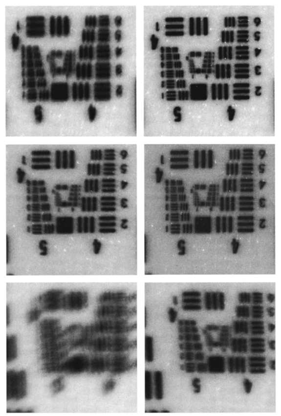 4.DiscussionThis study has shown that the MMDM offers a reasonable alternative to conventional piezodriven adaptive mirrors and spatial light modulators. The potential advantage is the low cost of this device compared to competing devices while maintaining the high reflectivity of a mirror surface. The disadvantage of this type of device is the nonuniform characteristic response of the continuous membrane surface and the associated problems in compensating. The process of compensation requires iterative adjustments that require a certain amount of time to be completed. The wave front compensator is capable of correcting static higher order aberrations. Further refinement to our optical setup is required to allow easier defocus adjustment. Faster computers and better software interfaces will allow faster processing time and thus our iterative approach will reach a steady state more rapidly. Hofer and associates have developed a real time Hartmann–Shack wave front sensor that can sample at frequencies of up to 60 Hz.15 Currently, our camera is limited to two frames per second. A faster camera will allow quicker measurement and quicker compensation. Further research with smaller field of view needs to be done. The limitations of the MMDM are based on the limited deflection range of the MMDM and the low number of electrodes in our MMDM. Other researchers have used piezodriven mirrors4 9 16 that have a significantly larger deflection range. Additionally, our MMDM has only 19 electrodes, while the system used by others has 37 elements. In general, MMDMs use continuous membrane mirrors and are thus constrained by their continuous surface. However, this feature is likely to be less of a problem since the optical surfaces of the human eye are also continuous. One would not expect large variations in neighboring regions. The bigger problem is likely to be the nonuniform response of the surface to electrical stimulation. When comparing MMDMs to segmented mirrors it appears that MMDMs have an advantage as they cover 100 area of the mirror surface. Segmented mirrors have gaps between mirror elements that cause light loss and may cause interference. It appears that the main limitation of MMDMs are the limited deflection and lower number of electrodes. An area that has only recently become of interest is digital image restoration based on deconvolution.17 18 19 20 21 Our group has experience in applying blind deconvolution algorithms to angiographic images recorded with a scanning laser ophthalmoscope. One limitation of blind deconvolution is that we have to estimate the point-spread function and use it to reconstruct the original image. In an iterative approach, we calculate the original image and the point-spread function based on intelligent guessing. By using the measured wave front and its associated point-spread function, a better and faster deconvolution can be achieved. Adaptive optics can be applied to conventional fundus cameras and scanning laser ophthalmoscopes as well. Scanning laser ophthalmoscopes offer the advantage of lower light levels and high image contrast.22 They are ideally suited for adaptive optical applications. The entire field of scanning laser ophthalmoscopy and tomography can benefit from adaptive optical components. Angiography23 24 will allow more detailed analysis of fine vessel structures in diseases such as diabetic retinopathy, age-related macular degeneration, and macular edema. Confocal tomography25 26 27 28 29 will benefit from improved reproducibility and thus may allow earlier diagnosis of diseases such as glaucoma, epiretinal membranes, and others. In conclusion, low-cost adaptive optics are an option for conventional retinal imaging devices and will offer a significant improvement in resolution over existing imaging techniques. AcknowledgmentsThis study was supported by the Whitaker Foundation, NEI EY07366 (W.R.F.), NEI EY13304 (D.U.B.), the National Science Foundation (S.F.), and Research to Prevent Blindness. REFERENCES
J. Bille
and
U. Klingbeil
,
“Laser scanning ophthalmoscope with active focus control,”
Invest. Ophthalmol. Visual Sci. , 22
(23), 58
(1982). Google Scholar
A. W. Dreher
,
J. F. Bille
, and
R. N. Weinreb
,
“Active optical depth resolution improvement of the laser tomographic scanner,”
Appl. Opt. , 28
(4), 804
–808
(1989). Google Scholar
F. Vargas-Martı´n
,
P. M. Prieto
, and
P. Artal
,
“Correction of the aberrations in the human eye with a liquid-crystal spatial light modulator: limits to performance,”
J. Opt. Soc. Am. A , 15
(9), 2552
–2562
(1998). Google Scholar
J. Liang
,
D. R. Williams
, and
D. T. Miller
,
“Supernormal vision and high-resolution retinal imaging through adaptive optics,”
J. Opt. Soc. Am. A , 14
(11), 2884
–2892
(1997). Google Scholar
J. Cho
,
S. T. Thurman
,
J. T. Donner
, and
G. M. Morris
,
“Characteristics of a 128×128 liquid-crystal spatial light modulator for wave-front generation,”
Opt. Lett. , 23 969
–971
(1998). Google Scholar
G. D. Love
,
“Wave-front correction and production of Zernike modes with a liquid-crystal spatial light modulator,”
Appl. Opt. , 36 1517
–1524
(1997). Google Scholar
M. A. A. Neil
,
M. J. Booth
, and
T. T. Wilson
,
“Dynamic wave-front generation for the characterization and testing of optical systems,”
Opt. Lett. , 23 1849
–1851
(1998). Google Scholar
D. T. Miller
,
D. R. Williams
,
G. M. Morris
, and
J. Liang
,
“Images of cone photoreceptors in the living human eye,”
Vision Res. , 36
(8), 1067
–1079
(1996). Google Scholar
A. Roorda
and
D. R. Williams
,
“The arrangement of the three cone classes in the living human eye (see comments),”
Nature (London) , 397 520
–522
(1999). Google Scholar
A. Roorda
,
“Adaptive optics ophthalmoscopy,”
J. Refract. Surg. , 16
(5), S602
–607
(2000). Google Scholar
G. Vdovin
and
P. M. Sarro
,
“Flexible mirror micromachined in silicon,”
Appl. Opt. , 34 2968
–2972
(1995). Google Scholar
L. J. Zhu
,
P. C. Sun
,
D. U. Bartsch
,
W. R. Freeman
, and
Y. Fainman
,
“Adaptive control of a micromachined continuous-membrane deformable mirror for aberration compensation,”
Appl. Opt. , 38
(1), 168
–176
(1999). Google Scholar
L. J. Zhu
,
D. U. Bartsch
,
W. R. Freeman
,
P. C. Sun
, and
Y. Fainman
,
“Modeling human eye aberrations and their compensation for high-resolution retinal imaging,”
Optom. Vision Sci. , 75
(11), 827
–839
(1998). Google Scholar
J. Z. Liang
,
B. Grimm
,
S. Goelz
, and
J. F. Bille
,
“Objective measurement of wave aberrations of the human eye with the use of a Hartmann–Shack wave-front sensor,”
J. Opt. Soc. Am. A , 11
(7), 1949
–1957
(1994). Google Scholar
H. Hofer
,
P. Artal
,
B. Singer
,
A. Juan Luis
, and
D. R. Williams
,
“Dynamics of the eye’s wave aberration,”
J. Opt. Soc. Am. A , 18
(3), 497
–506
(2001). Google Scholar
J. Liang
and
D. R. Williams
,
“Aberrations and retinal image quality of the normal human eye,”
J. Opt. Soc. Am. A , 14
(11), 2873
–2883
(1997). Google Scholar
D. U. Bartsch, A. J. Mueller, N. O’Connor, T. Holmes, and M. D. Freeman, “
“3-D reconstruction of blood vessels in the ocular fundus from confocal scanning laser ophthalmoscope ICG angiography,” in Proceedings of 3rd IEEE International Conference on Image Processing, 16–19 Sept. 1996, Lausanne, Switzerland, Vol. 683, pp. 687–690, IEEE, New York (1996,”
D. U. Bartsch
,
A. J. Mueller
,
N. O’Connor
,
T. Holmes
, and
W. R. Freeman
,
“Improved visualization of ocular microvascularization in patients with melanoma and other diseases using computer image processing,”
Invest. Ophthalmol. Visual Sci. , 38 S807
(1997). Google Scholar
D. U. Bartsch
,
N. O’Connor
,
T. Holmes
,
A. J. Mueller
,
R. Folberg
, and
W. R. Freeman
,
“ICG angiographic visualization of prognostically significant microvascular patterns in choroidal melanoma: resolution improvement,”
Ger. J. Ophthalmol. , 6 S159
(1997). Google Scholar
N. J. Oconnor
,
D. U. Bartsch
,
W. J. Freeman
,
A. J. Mueller
, and
T. J. Holmes
,
“Fluorescent infrared scanning-laser ophthalmoscope for three-dimensional visualization: automatic random-eye-motion correction and deconvolution,”
Appl. Opt. , 37
(11), 2021
–2033
(1998). Google Scholar
C. J. Holmes
,
R. Hoge
,
L. Collins
,
R. Woods
,
A. W. Toga
, and
A. C. Evans
,
“Enhancement of MR images using registration for signal averaging,”
J. Comput. Assist. Tomogr. , 22
(2), 324
–333
(1998). Google Scholar
D. U. Bartsch
,
R. N. Weinreb
,
G. Zinser
, and
W. R. Freeman
,
“Confocal scanning infrared laser ophthalmoscopy for indocyanine green angiography,”
Am. J. Ophthalmol. , 120
(5), 642
–651
(1995). Google Scholar
W. R. Freeman
,
D. U. Bartsch
,
A. J. Mueller
,
A. S. Banker
, and
R. N. Weinreb
,
“Simultaneous indocyanine green and fluorescein angiography using a confocal scanning laser ophthalmoscope (see comments),”
Arch. Ophthalmol. (Chicago) , 116
(4), 455
–463
(1998). Google Scholar
D. U. Bartsch
,
M. Intaglietta
,
J. F. Bille
,
A. W. Dreher
,
M. Gharib
, and
W. R. Freeman
,
“Confocal laser tomographic analysis of the retina in eyes with macular hole formation and other focal macular diseases,”
Am. J. Ophthalmol. , 108
(3), 277
–287
(1989). Google Scholar
D. U. Bartsch
and
W. R. Freeman
,
“Laser-tissue interaction and artifacts in confocal scanning laser ophthalmoscopy and tomography,”
Neurosci. Biobehav. Rev. , 17
(4), 459
–467
(1993). Google Scholar
D. U. Bartsch
and
W. R. Freeman
,
“Axial intensity distribution analysis of the human retina with a confocal scanning laser tomograph,”
Exp. Eye Res. , 58
(2), 161
–173
(1994). Google Scholar
R. N. Weinreb
,
M. Lusky
,
D. U. Bartsch
, and
D. Morsman
,
“Effect of repetitive imaging on topographic measurements of the optic nerve head,”
Arch. Ophthalmol. (Chicago) , 111
(5), 636
–638
(1993). Google Scholar
|


CITATIONS
Cited by 19 scholarly publications and 1 patent.
Micromachined deformable membrane mirrors
Wavefronts
Eye
Mirrors
Adaptive optics
Electrodes
Image resolution


