1.IntroductionLasers have tremendous potential as high-precision surgical devices because they can be focused to a small spot and wavelengths can be selected that are either strongly or selectively absorbed in the target tissue. While numerous ablation modes and interaction mechanisms exist, tissue ablation in eloquent structures of the body, such as the brain or eye, requires precise ablation of the target tissue while minimizing collateral damage to adjacent tissue structures. Of the existing conventional laser sources, particularly those in the UV (<300 nm) and in the IR (>2.7 μm) have been shown to exhibit very strong absorption in soft tissue.1 A limiting factor in using many laser sources in these absorption bands, however, is the lack of adequate optical fibers. Regular silica fi-bers, including low-OH fibers, transmit from 350 to 2500 nm. Practically speaking, this has limited the surgical applications of many of these lasers, in particular when ablation in a liquid environment is required, as is the case of vitreoretinal surgery. Perhaps the laser most utilized for these applications has been the erbium:yttrium aluminum garnet (Er:YAG) laser, which can be delivered via specialty fiber optics made of materials such as sapphire or zirconium fluoride.2 3 4 5 Nevertheless, while the collateral thermal damage induced by the Er:YAG laser is small, it is not negligible. An important reason for this is that the pulse duration of the free-running Er:YAG laser is typically on the order of 250 μs FWHM, allowing significant thermal diffusion since this pulse duration is significantly longer than the thermal diffusion time (approximately 1.6 μs) given an optical penetration depth of ∼1 μm at the 2.94 μm wavelength. Alternatively, the Q-switched Er:YAG laser typically has a pulse duration of 40 to 100 ns FWHM and hence is thermally confined. However, this shorter pulse duration has been shown to result in more explosive ablation and can lead to increased mechanical damage owing to explosive bubble expansion and collapse, in particular when it is applied in close vicinity to solid boundaries where cavitation can result in damaging jet formation. In a related scenario, collateral damage may be caused by mismatch of acoustical impedance boundaries, resulting in strong pressure transients. This may also be true for the free-running Er:YAG laser, which has 1-μs spikes during its pulse. Consequently, the search for alternative lasers and laser parameters has been a continuing quest. Recent research using a free electron laser (Vanderbilt University Mark III FEL), a tunable infrared source, has provided strong evidence that ablation at wavelengths near λ=6.45 μm results in tissue ablation with minimal collateral damage (<40 μm) yet yields a high ablation rate that is useful for human surgery. In biological soft tissue, this wavelength of light is coupled into the vibrational modes of water molecules (symmetric and asymmetric stretch)6 as well as the vibrational mode of the amide-II bond. It has been postulated that this direct absorption by the essential bond in the backbone of most structural proteins has the potential to reduce the tissue integrity, thus allowing efficient ablation of ocular and neural tissue with minimal collateral damage.7 8 In addition, the FEL pulse consists of a 5-μs macropulse, which is made up of a micropulse train of 1-ps pulses at 3 GHz. The relative contributions of the FEL pulse structure and specific wavelength to the ablation process continue to be the subject of investigation.9 10 11 Based on various preclinical studies,8 12 13 14 15 16 17 18 19 two clinical protocols are currently under way that utilize the Mark III FEL in neurosurgical (brain tumor resection) and ophthalmologic (optic nerve fenestration) applications. While these studies are still ongoing, preliminary results suggest that the FEL at 6.45 μm is able to ablate biological soft tissue in vivo in humans with minimal and sometimes undetectable collateral damage. To date, the delivery of midinfrared laser radiation (for the purpose of this study defined as light in the wavelength range from 6 to 7 μm) has been limited to that in air and thus to applications in which the target tissue can be readily exposed. It should be noted that the fiber optic materials that are used for transmission of the Er:YAG wavelength (sapphire and zirconium fluoride) do not transmit in the 6 to 7-μm range. In this study we explore the possibility of using the FEL at the midinfrared part of the spectrum (6 to 7 μm) delivered via optical fibers to ablate eloquent target structures in a liquid environment. While there are numerous examples of applications that would benefit from this approach, we focus on one of the most obvious ones: vitreoretinal procedures. The use of laser light with adequate cutting capabilities in vitreoretinal surgery would allow safe and extended tractionless removal of different types of vitreoretinal membranes, as well as retinotomy and retinectomy.20 Various researchers have investigated the use of the Er:YAG laser in retinal and vitreous surgery and concluded that it is an effective tool for the complete transection of vitreous membranes as well as the creation of retinectomies in detached retinas. Nevertheless, although the Er:YAG laser has been shown to produce precise tissue transection and ablation,21 22 23 24 25 there are two main problems in using infrared-laser radiation in an aqueous environment such as the vitreous. First, the aqueous environment by virtue of its strong absorption coefficient for laser radiation greatly impedes the amount of laser radiation that actually reaches the target tissue unless the delivery fiber is in direct contact with this target tissue. This in turn increases the risk of mechanically damaging the delicate structures in the retina and retinal nerve layer. Second, the formation of fast expanding and subsequently collapsing water vapor bubbles at a submerged fiber tip may cause mechanical damage both directly or indirectly owing to the generation of strong pressure transients.26 27 In order to deliver midinfrared light to vitreoretinal tissues, a delivery system through a liquid environment needs to be devised. In addition to a delivery fiber able to transmit the wavelength range of interest, the laser radiation needs to be delivered to the target retinal layer. Given the absorption coefficient of vitreous in the 6 to 7-μm range (μa∼80 mm −1) and the macropulse duration of the FEL of only 5 μs (compared with the Er:YAG laser’s 250 μs, which allows delivery through a laser-induced vapor channel), this means that either the fiber needs to be in contact with the tissue or the infrared-absorbing vitreous needs to be replaced with a liquid that does not absorb the infrared laser radiation. When using the Er:YAG laser for this application, Wesendahl et al.;24 replaced the vitreous with perfluorodecalin, a member of the perfluorocarbon family, which is routinely used as a temporary vitreous substitute to prevent retinal detachments during vitreoretinal procedures.28 Perfluorocarbon liquids (PFCLs) [CF 3(CF 2)n CF 3] have many characteristics that make them beneficial for vitreoretinal applications, including the following: high specific gravity, low viscosity, and immiscibility in water. In addition, perfluorocarbons conveniently have the added characteristic of relative transparency in the infrared part of the spectrum with a μa=0.05 mm −1 at λ=2.94 μm. 24 Perfluorocarbon liquids were first evaluated for medical use as oxygen carriers in 1966.29 They were first used as vitreous substitutes and employed clinically for vitreoretinal surgery in 1987.30 31 The introduction of PFCLs has enhanced the success rate of many vitreoretinal surgical procedures. Their high specific gravity allows the hydrokinetic stabilization of the retina on the posterior pole of the eye during surgery. By this means, the retina is flattened and the subretinal fluid can be displaced without a posterior retinotomy.3 Currently, the Vanderbilt free electron laser is one of the few lasers in the world that has the capability of delivering the λ=6.45-μm wavelength with sufficient pulse energy and average power to be useful for medical applications. However, in the next few years, alternative technologies based on solid-state developments (OPOs) as well as other lasers will become available and have output characteristics that will make them amenable to medical applications on a broader scale. At that time, delivery devices will be necessary to adapt this technology to clinical investigations. The goal of this study is to investigate the potential of the 6.45-μm-wavelength pulsed infrared laser for ablation in a liquid environment. To this end we have explored transmission and threshold damage characteristics of two different IR-transmitting fiber optic materials and have explored the use of perfluorocarbon liquids as midinfrared transparent liquid vitreous substitutes. The ablation characteristics of a water-rich tissue phantom through several perfluorocarbon liquids were documented. 2.Materials and Methods2.1.Fiber Delivery of 6.45-μm Laser PulsesSilver halide fibers (AgCl0.4Br0.6; School of Physics and Astronomy, Tel Aviv University) and arsenic sulfide fibers (Naval Research Laboratory, Washington, D.C.) were tested for transmission characteristics at the wavelengths of interest (2.94, 6.1, and 6.45 μm). The silver halide fibers (AgCl (x) Br (1−x)) were 700 μm in diameter and were core only. The samples used were typically 20 cm in length, but fibers with 2-m lengths were available and were AgCl 0.6 Br 0.4. The arsenic sulfide fibers (part of the chalcogenide glass family of materials) were 800 μm in diameter core and were core with cladding. These fibers were typically 100 cm in length and were tested to determine their damage thresholds with respect to the high peak power of the FEL, which is on the order of ∼GW/cm 2. This high peak irradiance is due to the unique pulse structure of the FEL. It is the picosecond micropulse that leads to the high peak irradiance that is inherent with the FEL used. The Vanderbilt University FEL was used as a test laser for transmission and damage threshold experiments. The laser light was sent through a double Brewster plate polarizer (II–VI Inc., Saxonburg, Pennsylvania), which allowed continuous variation of the laser power. This polarizer was mounted on a motorized rotation stage in the vacuum beam line of the FEL and controlled by a vacuum feedthrough controller (New Focus, San Jose, California). In all experiments the laser was tweaked to ensure a pulse-to-pulse variation in energy of less than 10, measured over 500 pulses. After it left the vacuum beam transport system via a BaF 2 window, the light was then focused onto the face of a fiber with a 2-in.-diameter, 200-mm focal length CaF 2 lens. The beam profile was determined to be a Gaussian into the fiber and a top hat with varying hot spots out of the fiber by guiding the beam onto a Spiricon beam profiler. The fiber was positioned just beyond the focal point of the lens in order to avoid focusing inside the fiber. The coupling was maximized for transmitted power. The experiment was repeated for multiple fiber samples (n⩾3) at λ=2.94, 6.1, and 6.45 μm. By rotating the polarizer, the input energy was slowly increased from the minimum the polarizer would allow (∼0.5 mJ/pulse) up to the point of fiber failure. The input power as well as the transmitted power was determined by using a Molectron EPM 2000 laser energy meter (Molectron Detector Inc., Portland, Oregon). Energy input to the fiber was measured just after the coupling lens using a Molectron J-50 detector. The energy transmitted through the fiber was measured by placing the detector within 1 cm from the distal end of the fiber. The transmission was determined as a function of wavelength, input energy, and fiber length. Three samples of each fiber type were used to determine the average transmission for each fiber material. By using two different lengths of fiber samples, losses due to coupling and Fresnel reflections were decoupled from bulk losses in the fiber material. In all fibers the damage threshold was defined as the input energy level at which the transmission of the fiber started to drop, i.e., failure. 2.2.Optical Property Determination of Perfluorocarbon LiquidsSeven different perfluorocarbon liquids (3M, St. Paul, Minnesota; F2 Chemicals Ltd., Lea Town, Preston, UK; Oakwood Products Inc., West Columbia, South Carolina) of varying composition, chain length, and branching were tested for their absolute absorption properties in the infrared from 2 to 10 μm. The infrared spectra were obtained using a Bruker IFS 66-V Fourier transform infrared (FTIR) spectrometer in the transmission mode through a 500-μm sample chamber. The infrared spectra of the PFCLs were compared with that of saline. Saline was used as a control to simulate the makeup of vitreous humor. The absolute transmission measurements from the FTIR were used to calculate the absorption coefficient of the PFCLs. The FTIR data were then compared with data obtained by a Beer’s law experiment using the FEL to determine whether the unique pulse structure of the FEL and the high intensities of the laser caused any differences in the absorption properties of the materials tested. The relevant material properties of the seven PFCLs tested (to the extent they are known or provided by the manufacturers) are shown in Table 1. Table 1
To verify the FTIR data at selected wavelengths and to investigate the effect of intensity and pulse profile on the absorption rate, a Beer’s law experiment was performed by coupling the light at the three wavelengths of interest (2.94, 6.1, and 6.45 μm) into a silver halide fiber. The fiber was then placed inside a homemade sample chamber in which the bottom consisted of CaF 2 so that the mid-IR light could be transmitted through the bottom of the chamber and measured by a detector immediately below the chamber. The chamber was filled with each PFCL and the fiber was translated away from the CaF 2 window in 200-μm increments by a Newport translation stage (Newport, Irvine, California) until a distance of 4 mm was obtained or no measurable transmission could be detected. The transmission through the bottom of the sample chamber was measured at each increment using the power meter. An average of 50 pulses with a repetition rate of 15 Hz was recorded. An exponential fit to the transmission versus distance curve yielded the absorption coefficient of the liquid. In these experiments the imaging setup (see Sec. 2.3) was used to ensure that the radiant exposure at the fiber’s distal end was low enough to avoid bubble formation or cavitation effects that could influence the transmission measurements. 2.3.Target Ablation Through Perfluorocarbon LiquidA standard pump-probe imaging technique was used to image the ablation process at the distal end of the fiber.32 This method was used to document the ablation dynamics both in the PFCL alone as well as the ablation of a tissue phantom through the PFCL. Based on the fiber testing experiments, we used a silver halide fiber for the ablation experiments. The source for the imaging illumination was a nitrogen dye laser (Laser Photonics LN 1000), with a rhodamine dye module operating at 644 nm (Laser Photonics LN 102). The timing between the FEL pulse (pump) and the nitrogen dye pulse (probe) was set using a digital delay-pulse generator (Stanford Research Systems Inc., model DG535). The output of the nitrogen dye probe laser was coupled into a 600-μm multimode fiber with a length of ∼1000 m. This fiber length significantly reduces the coherence of the probe light and hence improves the image quality by eliminating speckle. A standard black-and-white CCD camera was used with a frame rate of 30 Hz to record the images onto an S-VHS videotape. The images were then digitized using an ATI Rage-Pro Mobility video card for processing and analysis. The ablation of the liquid was performed using perfluorodecalin (which has a high boiling point), PF-5060 (which has a low boiling point), and water at a 6.45-μm wavelength with the FEL. For these experiments the silver halide fiber was placed in a horizontal position in order to avoid trapping gas bubbles underneath the fiber tip. The fiber was inserted through a watertight port that was built into a glass cuvette. The tissue phantom used was gelatin that was 90 water by weight. The ablation of the tissue phantom was done using perfluorodecalin at wavelengths of 2.94 and 6.45 μm. The setup for the tissue phantom ablation was the same as for the liquid ablation except that the fiber orientation was vertical and the tissue phantom was placed in the bottom of the cuvette. In order to quantify the effect of varying the distance of the fiber from the target in perfluorodecalin, the tissue phantom ablation experiment was repeated at λ=6.45 μm by varying the distance of the fiber from the target surface and the number of pulses delivered. The ablation depth was then determined for each data point for quantification. 3.ResultsThe results of the fiber experiments are summarized in Table 2. At λ=6.45 μm, the silver halide fibers, including all the coupling and Fresnel losses, were able to transmit 60 of the incident light for a fiber length of approximately 20 cm. The arsenic sulfide fibers are known to have a fairly significant dropoff in transmission above λ=6.2 μm so they were tested at a wavelength of 6.1 μm. The bulk losses of both fiber materials were approximately the same (0.54 dB/m or 11.7/m and 0.62 dB/m or 13/m, respectively). The damage threshold of the silver halide fibers was significantly lower than that of the arsenic sulfide fibers (7.8 J/cm 2 versus 15.9 J/cm 2) , where these numbers represent the threshold radiant exposure (at the center of the Gaussian) per macropulse with the laser running at 30 Hz. Derived from this are the peak irradiance damage threshold values (calculated per micropulse of 1 ps). These values are 0.54 GW/cm 2 and 1.12 GW/cm 2 for the silver halide and arsenic sulfide fibers, respectively. Practically speaking, in the 20-cm-long fiber samples of silver halide, we were reliably transmitting up to 7 mJ (output energy) per macropulse (5 μs) at 30 Hz through a 700-μm diameter fiber for an extended period of time (>10 min). This represents a radiant exposure of 1.82 J/cm 2 at the distal fiber surface, which was sufficient to conduct the ablation experiments (H th =0.41 J/cm 2 for water at λ=6.45 μm and H th =0.0326 J/cm 2 for water at λ=2.94 μm) .33 34 In addition, although they were not quantitatively analyzed in this study, the silver halide fibers are more flexible, softer, and bendable than the rather stiff and brittle arsenic sulfide fibers. Moreover, when they were damaged at the surface, the silver halide fibers could fairly easily be re-cut without the need for polishing while the arsenic sulfide fibers are difficult to cut and need to be polished. This, together with the equivalent loss characteristics, led us to choose the silver halide fibers for the rest of the experiments. Table 2
FTIR analysis on the seven PFCLs showed no significant differences in the absorption curves for all the PFCLs tested in the range from 2 to 7 μm. Beyond 7 μm, some differences were observed, but this was outside of the region of interest for this study. Figure 1 shows the absorption curves for five of the seven PFCLs: perfluorodecalin, perfluoroperhydrofluorene, and perfluoromethyldecalin, as well as 3M’s proprietary PFCLs coded PF-5070 (mostly a seven-carbon backbone) and PF-5080 (mostly an eight-carbon backbone). The remaining two PFCLs, PF-5060 and perfluoro-1,3-dimethylcyclohexane, are not shown in the figure but had absorption curves that were indistinguishable from the ones plotted here. It can be seen that the absorption coefficient for wavelengths<3.8 μm is negligible (and is not accurately measurable with the 500-μm-thick sample chamber of the FTIR). For wavelengths>5 μm, the absorption coefficient increases and at 6.45 μm it equals approximately 3 mm −1 for all PFCLs tested. Figure 2 shows that saline has an absorption coefficient at least 2 orders of magnitude higher than perfluorodecalin at the wavelengths of interest (λ=2.94, 6.1, and 6.45 μm), indicating the potential advantage of the perfluorodecalin as a vitreous substitute for infrared laser delivery. Figure 3 shows the absolute absorption coefficients of the seven PFCLs at the three wavelengths of interest as obtained from the Beer’s law experiment. These values confirmed the values obtained from the FTIR experiments, indicating that the absorption coefficients of the PFCLs are independent of the pulse structure or intensity of the FEL. This figure shows that the absorption coefficient rises from 0.084 mm −1 at λ=2.94 μm to 3.36 mm −1 at λ=6.45 μm, but is not significantly different among the seven different PFCLs. Figure 1FTIR spectra for five of the seven different perfluorocarbon liquids tested. It can be seen that all five of these spectra are nearly identical throughout the 2 to 7-μm wavelength of interest and deviate only slightly beyond 7 μm. The remaining two PFCLs (PF-5060 and perfluoro-1,3-dimethylcyclohexane) had similar curves (not shown here). Note that there is no measurable absorption of light (in the 500-μm cuvette used in the FTIR) in the 2 to 3.5-μm range. 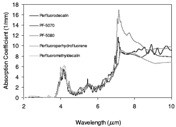 Figure 2A comparison of the FTIR spectra for perfluorodecalin and saline. From these spectra it is clear that the absorption coefficient of saline (vitreous) is at least 2 orders of magnitude higher at the midinfrared wavelengths of interest (λ=6.45 μm) and approximately 4 orders of magnitude higher at λ=2.94 μm than the absorption coefficient of perfluorodecalin. This is of great significance because it indicates that a vast improvement in light transmission can be obtained by replacing the vitreous with a substitute such as perfluorodecalin. 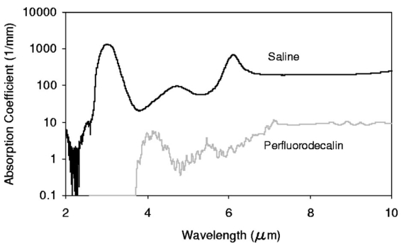 Figure 3A plot of the absorption coefficients for all seven PFCLs at the three target wavelengths obtained from the Beer’s law experiments. The absolute values of the absorption coefficients correlate very closely (within 5) with the results obtained from the FTIR experiment. All seven PFCLs have similar absorption coefficients for each wavelength, varying from 0.05 to 0.1 mm −1 at λ=2.94 μm and ∼3 mm −1 at λ=6.45 μm.  The pump-probe imaging was first performed in saline to compare it with pump-probe imaging that had been done with non-FEL lasers to determine whether the process of bubble formation with the FEL was comparable to that of other lasers such as the holmium:YAG (Ho:YAG) laser. In fact, with a μa=3 mm −1, the absorption coefficient for the FEL at λ=6.45 μm in PFCL is equivalent to the absorption coefficient of the Ho:YAG laser (λ=2.1 μm) in water. Figure 4 shows the results of this experiment. It can be seen in this figure that the vapor bubble grows until 70 μs after the onset of the laser pulse and then starts to collapse. Note that the laser pulse itself is only 5 μs in duration. At 130 μs after the start of the pulse, the bubble has collapsed, and the rebound bubble is ejected from the tip of the fiber. Figure 4The chronicle of ablation of water at λ=6.45 μm using the fast-flash pump-probe imaging setup. A 700-μm-diameter silver halide fiber was used to deliver a macropulse energy of 5 mJ (radiant exposure 1.3=J/cm 2) with a duration of 5 μs at a repetition rate of 5 Hz. Images were taken starting at the beginning of the FEL pulse through 130 μs after the start of the pulse. The vapor cavity continues to expand for 70 μs and subsequently collapses at approximately 110 μs, followed by a rebound bubble that ejects away from the solid face of the fiber (130 μs). 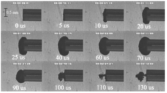 Figure 5 shows the results of the laser delivery in PF-5060, which is the PFC with the lowest boiling point available to us (see Table 1). There are several differences from the irradiation of saline that stand out. As early as 1 μs after the onset of the laser pulse, thermal stress lines (Schlieren effect) can be seen in the liquid immediately in front of the fiber. This effect is more pronounced at 5 μs. At 15 μs, bubble formation begins and continues until 100 μs. At 300 μs, multiple bubbles can be seen at the fiber tip. At 800 μs, the bubbles start floating away from the fiber tip to the surface. These bubbles can still be seen up to 50 ms after the pulse, which shows that the bubbles do not collapse as they do in water. Figure 5The chronicle of ablation for PF-5060 at λ=6.45 μm. A 700-μm-diameter silver halide fiber was used to deliver a macropulse energy of 5 mJ (radiant exposure 1.3=J/cm 2) with a duration of 5 μs at a repetition rate of 5 Hz. Images were taken starting at the beginning of the FEL pulse through 50 ms after the start of the pulse. In this series of images, lines of heating (Schlieren effect) as well as small bubble formation can be seen from the start of the pulse until 800 μs after the start. The bubbles remain long after the pulse, in contrast to those seen in water. These bubbles, unlike the transient vapor cavities seen in water, do not collapse and are still seen 50 ms after the pulse as they begin to float away from the fiber tip and up to the surface. 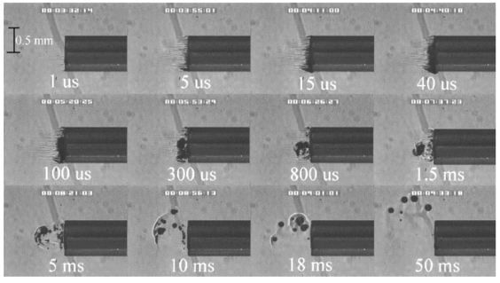 In contrast to both water and PF-5060, perfluorodecalin showed a very different pattern of ablation. Throughout the time course of the pulse as well as long after, only lines of heating (Schlieren effect) could be seen at the fiber tip. No bubble formation or cavitation of the perfluorodecalin itself was seen (Fig. 6) at the radiant exposures used in this experiment. Figure 6The chronicle of ablation for perfluorodecalin at λ=6.45 μm. A 700-μm-diameter silver halide fiber was used to deliver a macropulse energy of 5 mJ (radiant exposure 1.3=J/cm 2) with a duration of 5 μs at a repetition rate of 5 Hz. Images were taken starting at the beginning of the FEL pulse through 50 ms after the start of the pulse. This series of images shows increased heat deposition, indicated by the lines of heating (Schlieren effect) from the start of the pulse until 5 μs after the pulse. No bubble formation is observed at any time during or after the laser pulse. After the laser pulse, the heat that was generated during the pulse dissipates before the next pulse arrives. 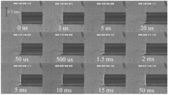 Figures 7 and 8 show the ablation dynamics of the gelatin tissue phantom in a perfluorodecalin environment for λ=2.94 and λ=6.45 μm, respectively. In both figures the image was captured at 100 μs after the onset of the laser pulse with the four panels representing the dynamics with the fiber positioned at various distances (1.0, 0.5, 0.3, and 0.0 mm) from the target tissue phantom. In Fig. 7 (with λ=2.94 μm) with the fiber at a distance of 1 mm from the target tissue, a clear ablation plume originating at the surface of the tissue phantom can be seen (left top panel). This shows that at λ=2.94 μm, ablation can easily be accomplished with the fiber tip as much as 1 mm away from the tissue surface. Once the fiber is brought to within 0.3 mm of the tissue, a large vapor cavity is seen between the fiber and the tissue surface. Figure 7The ablation of phantom tissue (gelatin with 90 w/w water) through perfluorodecalin at λ=2.94 μm. A 700-μm-diameter silver halide fiber was used to deliver a macropulse energy of 1.0 mJ (radiant exposure 0.26=J/cm 2) with a duration of 5 μs at a repetition rate of 5 Hz. All images were taken at 100 μs after the beginning of the pulse. The distance between the fiber tip and the tissue was changed from 1.0 mm (left top panel) down to 0.0 mm (right bottom panel). At a distance of 1.0 mm, an ablation plume can clearly be seen originating from the surface of the target with material being ejected from the target tissue. When the fiber is within 0.3 mm of the tissue, a large vapor cavity is formed between the fiber and the tissue since the fiber acts as a piston that prevents free escape of heated material. 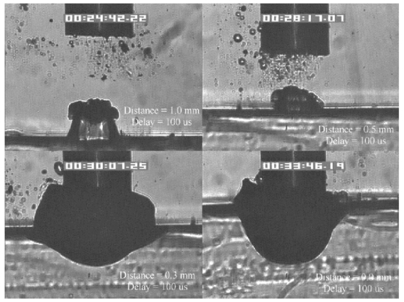 Figure 8Ablation of phantom tissue (gelatin with 90 w/w water) through perfluorodecalin at λ=6.45 μm. A 700-μm-diameter silver halide fiber was used to deliver a macropulse energy of 5.5 mJ (radiant exposure 1.43=J/cm 2) with a duration of 5 μs at a repetition rate of 5 Hz. All images were taken at 100 μs after the beginning of the pulse. The distance between the fiber tip and the tissue was changed from 1.0 mm (left top panel) down to 0.0 mm (right bottom panel). At d=1.0 mm, heat deposition in the PFCL is seen (Schlieren lines); however, no ablation of either the target tissue or the perfluorodecalin is observed. In contrast, at d=0.5 mm (right top panel), an ablation plume originating from the target tissue is visible, with ejection of material. When the fiber is brought within 0.3 mm of the tissue, a large vapor cavity originating from the target tissue is created, which is consistent with that seen at λ=2.94 μm.  Figure 8, in contrast (with λ=6.45 μm), shows that with the fiber positioned at a distance of 1 mm from the tissue surface, no ablation is seen. Under these conditions, no ablation of the target tissue was observed at any time after the laser pulse (not shown). Similar to the irradiation of just the perfluorodecalin (Fig. 6), the Schlieren lines, indicative of heating of the liquid in front of the fiber, are clearly seen. With the fiber at a distance of 0.5 mm from the target tissue, the first signs of an ablation plume originating from the target surface and ejected material can be seen. As the fiber to target distance is reduced even more, the same large vapor cavity was seen that was observed for λ=2.94 μm. Figure 9 shows the comparison of craters produced in the target tissue phantom by λ=2.94 and λ=6.45 μm for multiple pulses. This figure shows that ablation of the target tissue by delivering the laser radiation via the silver halide fiber and through a layer of 0.5 mm of perfluorodecalin is possible at both wavelengths, but the ablation efficiency is much greater at λ=2.94 μm. Figure 9The effect of multiple pulse delivery and crater drilling in target tissue through 0.5 mm of perfluorodecalin. Top row (left to right): 15, 30, and 45 pulses (λ=6.45 μm, macropulse energy=5.5 mJ, radiant exposure=1.43 J/cm 2) delivered through a 700-μm-diameter silver halide fiber. A small plume of ejected material is seen in the first frame after one pulse. After more pulses are delivered, the amount of material removed increases slightly and reaches a plateau as the effective distance between the fiber and bottom of the crater increases. A nontransient bubble forms at the fiber tip. Bottom row (left to right): 15, 30, and 45 pulses (λ=2.94 μm, macropulse energy=1.0 mJ, radiant exposure=0.26 J/cm 2) delivered through a 700-μm-diameter silver halide fiber. Large amounts of ejected material can be seen, with a growing crater being formed for each additional pulse. 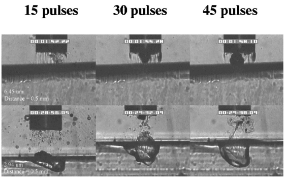 The results of the ablation depth experiment are shown in Fig. 10. The largest ablation depth of 587.5 μm was obtained after 500 pulses with the fiber in contact (z=0.0 mm) with the tissue phantom surface. With a fiber to target distance of z=0.7 mm, an ablation depth of 70 μm was seen with 500 pulses delivered. A negligible depth of only 10 μm was seen with a fiber to target distance of 1.0 mm. There was no detectable crater visible for any fewer than 500 pulses at this distance. Figure 10The ablation depth in gelatin as a function of the number of pulses delivered through perfluorodecalin was measured (λ=6.45 μm, macropulse energy=5.5 mJ, radiant exposure=1.43 J/cm 2) for different fiber to target distances. Gelatin with 90 (w/w) water was used as the target tissue phantom. The ablation crater depth was measured for different distances (z) between the silver halide fiber and the gelatin. ♦, z=0.0 mm (n=4); ▪, z=0.3 mm (n=3); ▴, z=0.5 mm (n=3); ×, z=0.7 mm (n=1); and * , z=1.0 mm (n=1). The number of pulses delivered at each of these distances was varied between 5 and 500. The crater depth was measured in real time on a high-magnification, close-up video image from a black-and-white CCD camera.  4.DiscussionIn order to extend and explore the use of pulsed midinfrared (6 to 7 μm) laser ablation of biological tissue to applications that require a liquid environment, we investigated a combination of optical fibers capable of transmitting these wavelengths as well as an infrared transparent family of perfluorocarbon liquids. We investigated the use of two different fiber optic materials capable of transmitting laser radiation in the wavelength range around 6.45 μm. The requirements for these delivery systems are twofold: (1) they must transmit the wavelength of interest and (2) they must tolerate the peak irradiance from the FEL pulse. Thus far, the delivery systems used for this wavelength include a modified articulated arm, a free beam delivery system with beam steering via two orthogonal galvanometric mirrors, and hollow waveguides.12 17 33 34 35 36 37 38 39 All of these systems have advantages and disadvantages in terms of transmission characteristics, damage thresholds, flexibility, and ease of use. However, they are all unable to deliver the laser radiation in a liquid environment. Only one of these methods, the hollow waveguide, can potentially be packaged to be used in a liquid environment and has the potential to be used in tight spaces that are difficult to access (i.e., in minimally invasive procedures).36 However, the hollow waveguides suffer from significant losses that vary in an unpredictable fashion when they are bent35 37 and require nitrogen purging. Hence, there is a need for fiber optic materials capable of delivering the laser radiation in this wavelength range. The materials tested in this study were silver halide, developed at Tel Aviv University40 and arsenic sulfide, developed at the U.S. Naval Research Laboratory.41 42 43 It was shown that both fiber materials have similar bulk losses (0.54 dB/m for silver halide and 0.62 dB/m for arsenic sulfide). Nagli et al.;40 reported losses of 0.2 dB/m for unclad silver halide fibers with similar diameters at λ=10.6 μm and noticed that the bulk losses depended on the wavelength used in combination with the Cl/Br ratio. Sanghera et al.;41 42 43 reported losses of 0.76 dB/m for the arsenic sulfide fibers. Hence our measured values for FEL transmission are in fair agreement with values reported in the literature. Practically speaking and assuming that a fiber length of approximately 2 m is desirable for medical applications, this means that both fibers can deliver a reasonable fraction of the incident light to the target tissue (roughly 80, not considering coupling losses). The most significant loss in both materials occurs as a result of the significant Fresnel losses that are due to the relatively high refractive indices of these materials (2.1 and 2.5, respectively). An obvious solution would be to equip the fibers with antireflective (AR) coatings. At present, AR coatings, to the extent that they are available for the wavelengths of interest, are unable to handle the peak irradiance from the pulsed laser source at the midinfrared (6 to 7 μm) wavelengths used. In a pilot experiment, an AR coating on the arsenic sulfide fiber had a damage threshold of approximately 0.1 J/cm 2 or 0.007 GW/cm 2, which is about 2 orders of magnitude less than the fiber itself (not shown). Damage thresholds for the arsenic sulfide fibers were shown to be a factor of 2 higher than those measured for the silver halide fibers (15.9 J/cm 2 versus 7.8 J/cm 2) . In both fiber materials, failure occurred at the input end of the fiber surface in all but one instance. Only in one of the arsenic sulfide fibers did we observe a fracture inside the bulk fiber material, which was attributed to a material defect. It was found that coupling geometry (placing the fiber beyond the focal plane of the coupling lens) and clean fiber ends (any dust particles greatly decreased the damage threshold) were essential in optimizing the damage threshold. It is worth noting that the silver halide fibers were tested at the desired wavelength of λ=6.45 μm while the arsenic sulfide fibers were tested at λ=6.1 μm. The primary reason for this is that the transmission of the arsenic sulfide fibers is known to drop off significantly beyond λ=6.1 μm. 44 Arsenic selenide, another member of the chalcogenide glass family, has been shown to transmit well up to λ=9 μm with bulk losses that are similar (0.73 dB/m) and hence would be appropriate to use at λ=6.45 μm. 43 However, in the current state of development, these fibers are inferior to the arsenic sulfide fibers with regard to the damage threshold, which is approximately half that of the arsenic sulfide fibers.42 Besides transmission and damage threshold characteristics, other factors to consider are fiber flexibility, brittleness, ease of handling, and toxicity. Based on these considerations, we elected to use the silver halide fibers for the ablation testing. In particular, the ease of handling, lack of brittleness, and softness of the silver halide material (the consistency resembles that of soldering wire) compared with the arsenic sulfide fibers make the silver halide fibers the material of choice. However, it should be noted that this is not a fundamental limitation of the chalcogenide fibers, but rather one that can be resolved by adequate cabling and packaging.45 The perfluorocarbon liquids were hypothesized to be infrared transparent liquids that allow transmission from the delivery fiber to the target tissue. It has been reported that for λ=2.94 μm this is indeed the case and the absorption coefficient has been reported to be on the order of 0.05 mm −1 (Refs. 24 and 46). In our experiments this finding was confirmed by both FTIR spectroscopy as well as the direct Beer’s law experiment with the FEL. In contrast, we found that at the midinfrared wavelengths of interest (λ=6.1 μm and 6.45 μm), the absorption coefficient is not negligible but rather is on the order of 2.07 mm −1 and 3.36 mm −1, respectively. However, these values are still about 2 orders of magnitude less than those of saline (and hence vitreous humor) for the same wavelengths. The seven different PFCLs did not show a significant difference in their optical properties at the wavelengths of interest. In addition, both the FTIR and Beer’s law–FEL experiments resulted in similar values for the absorption coefficient for a given material, indicating that there are no significant effects of the dynamic (i.e., intensity-dependent) optical properties. With the optical properties being roughly equal, other parameters need to be considered when selecting a PFCL of choice. Since one of the goals of using a nonabsorbing or minimally absorbing liquid is to avoid bubble formation and the associated potential of bubble collapse, acoustic transients, and mechanical damage, an obvious consideration is to select a PFCL with a high boiling point (see Table 1). Therefore, based on this consideration, perfluorodecalin, a ten carbon-backbone molecule with a boiling point of 142°C was selected for the ablation experiments. Moreover, the perfluorodecalin was shown to have the lowest absorption coefficient (Fig. 3), and is the most commonly used of the PFCLs in medical applications. In contrast, we also used the lowest boiling point PFCL, PF-5060 (3M), with a boiling point of 50 to 60°C (see Table 1). The pump-probe imaging revealed several events. First when λ=6.45 μm is delivered via the delivery fiber in saline, the events of bubble formation and collapse are as expected and in close agreement with what has been seen before in, for example, the fiber delivery of a Q-switched Er:YAG pulse in water.26 The penetration depth of light at λ=6.45 μm is approximately 12 μm in water (μa=80 mm −1) (Refs. 8 and 9) and the pulse (τp=5 μs) is relatively short compared with the bubble lifetime. Moreover the bubble dynamics closely follow the Rayleigh relationship for spherical water vapor cavities, which predicts that the lifetime of the bubble in milliseconds (in this case ∼0.11 ms) equals the bubble size in millimeters divided by 10 (in this case ∼0.105 mm) (Ref. 47). In contrast, the delivery of identical (same wavelength, and irradiance) laser pulses in the PFCL showed a very different behavior. In the low boiling-point PF-5060, the origination of a long-lived bubble was observed that did not collapse and eventually rose to the surface. In a separate experiment (not shown) we observed that this bubble, when trapped underneath the fiber, would remain for at least 1 h, indicating that this is not simply a gaseous phase of the PFCL but rather a unique gas that originated as a result of the laser irradiation. We speculate that the content of the gas bubble is either oxygen forced to dissociate from the PFCL (these liquids are known to reversibly bind oxygen and are being investigated as potential blood substitutes for this reason), or short-chain carbon gases that are generated by thermal or direct photo-dissociative effects. In perfluorodecalin no bubble formation (transient or residual) was observed at the radiant exposures used (1.3 J/cm 2). However, at higher radiant exposures, nontransient gaseous bubbles were observed at higher laser pulse repetition rates in particular (not shown). If indeed the bubble content is a breakdown product of the perfluorocarbon material, there may be a legitimate concern about potential toxicity effects. Tortelli and Tonelli48 reported that thermal decomposition of branched-chained perfluoroalkenes could indeed yield toxic compounds. Clearly, prior to engaging in clinical trial experiments, the contents of the produced gas must be determined. When perfluorodecalin is used as a delivery medium, laser-induced lines of heating (Schlieren effect) are observed. We believe that nonuniform heating (hot spots) in the mode of the beam exiting the fiber may have caused the streaky pattern immediately in front of the delivery fiber. The induced temperature gradients result in gradients in the refractive index, which shows up as dark and light streaks in the shadow-mode pump-probe imaging. This phenomenon is consistent with what has been observed in Ho:YAG laser ablation of water in which the absorption coefficient is equivalent (μa=3 mm −1) to that in PFCL at λ=6.45 μm (Ref. 27). Despite the fact that the input beam profile from the FEL is a Gaussian, transverse-electromagnetic (TEM 00) mode, the beam profile out of the silver halide fiber, measured with a Spiricon Pyrocam I beam profiler, was a top hat with significant hot spots (not shown), which caused the uneven heating of the PFCL. This may lead to thermal lensing, which is characterized by self-defocusing that is due to the temperature gradients, interference caused by spherical aberration of the thermal lens, and asymmetric distribution caused by thermal convection in a fluid medium. However, the extreme thermal lensing-induced self-defocusing that was observed by Frenz et al.;46 was not observed in our experiments. This is most likely because the pulse energy (and hence the total thermal load) used in our experiments was ∼40 times less. Our imaging experiments showed no evidence of generation of a pressure transient. Based on the fact that the laser pulse does not fulfill the requirements of stress confinement, no thermoelastic pressure wave is expected. Given the asymmetry of the bubble formation, bubble collapse is unlikely to cause significant collapse pressures. While we did not attempt to measure pressure transients associated with ablation of target tissue under PFC, Frenz et al.;46 reported pressure transients of <0.7 bar for similar experiments with the holmium and erbium lasers. We have shown that ablation of a tissue phantom target through PFCL using λ=6.45 μm is feasible. However, in contrast to the use of PFCL to transmit radiation at λ=2.94 μm, the delivery fiber needs to be in fairly close proximity to the target tissue because the optical penetration depth is only on the order of 0.33 mm. Practically speaking, for the proposed application of this laser delivery approach in vitreoretinal procedures, the distal end of the delivery fiber needs to be close to (<0.5 mm) but not in contact with the target tissue. An added advantage over using PFCLs in combination with the Er:YAG laser at λ=2.94 μm is that the process is self-limiting; as a crater is ablated in the target tissue, the distance between the fiber and target tissue (now the bottom of the crater) increases. Using the λ=6.45-μm wavelength in combination with perfluorodecalin, where the optical absorption is not insignificant but is much smaller than that of vitreous humor, allows a noncontact laser surgical procedure, yet remote (both lateral and axial) structures are effectively shielded because the radiant exposure of the beam reaching the target will fall below the ablation threshold (as shown in Fig. 10). This may optimize the efficacy and safety of laser-based vitreoretinal surgery. This study has shown the feasibility of an approach to delivering laser radiation in the midinfrared at radiant exposures above the threshold for tissue ablation by fiber optics and in a liquid environment. This method shows much promise for retinal surgical applications and has significant implications for other applications that may benefit from the use of these wavelengths in laser surgery. 5.ConclusionsThe data presented here show the feasibility of fiber delivery of high-power pulsed midinfrared laser radiation at λ=6.45 μm using silver halide and arsenic sulfide fibers at clinically useful radiant exposures in a liquid environment. The bulk losses of the two fibers are comparable while the coupling losses in these high refractive index materials represent the most significant loss of light. Silver halide fibers were found to be easier to handle and more flexible, which made them the fiber of choice for our experiments. All of the perfluorocarbon liquids tested had similar absorption characteristics for the wavelengths of interest. In contrast to the absorption coefficient of the PFCLs at λ=2.94 μm, which is effectively negligible, at λ=6.45 μm the absorption coefficient of the PFCLs is ∼3 mm −1. Pump-probe imaging showed the ablation sequence (λ=6.45 μm) at the fiber tip in a water environment, which revealed a fast expanding and collapsing bubble. In contrast, the volatile PF-5060 showed no fast bubble expansion and collapse but rather formation of nontransient gas bubbles. Perfluorodecalin did not show any bubble formation at the radiant exposures used. It was shown that using the λ=6.45-μm wavelength delivered via fiber optics in combination with perfluorodecalin allows a noncontact laser surgical procedure. Depending on the radiant exposure from the fiber, ablation through several hundred micrometers of PFCL is possible, in contrast to the limited penetration through in vivo vitreous humor. Perfluorodecalin offers a great improvement in enabling noncontact ablation of target structures, while allowing deeper structures to be shielded because the radiant exposure of the beam reaching the target will fall below the ablation threshold. This may optimize the efficacy and safety of laser-based vitreoretinal surgery. This study has shown the feasibility of an approach to delivering laser radiation in the midinfrared at radiant exposures above the threshold for tissue ablation by fiber optics and in a liquid environment. This method shows promise for retinal surgical applications and has significant implications for other applications that may benefit from the use of these wavelengths in laser surgery. AcknowledgmentsThis work was funded by the U.S. Department of Defense (AFOSR award No. F49620-01-1-0429). The authors would like to thank Dr. Borislav Ivanov, Vanderbilt University Physics Department, for providing us with PF-5060, PF-5070, PF-5080, and perfluorodecalin; F2 Chemicals Ltd., UK, for providing us with perfluorodecalin, perfluoromethyldecalin, perfluoro-1,3,-dimethylcyclohexane, and perfluoroperhydrofluorene; and the W. M. Keck Foundation Free Electron Laser Center staff for their help throughout the completion of this work. REFERENCES
A. J. Welch
,
M. Motamedi
,
S. Rastegar
,
G. L. LeCarpentier
, and
D. Jansen
,
“Laser thermal ablation,”
Photochem. Photobiol. , 53 815
–823
(1991). Google Scholar
M. L. McHam
,
D. L. Eisenberg
,
J. S. Schuman
, and
N. Wang
,
“Erbium:YAG laser sclerectomy with a sapphire optical fiber,”
Ophthalmic Surg. Lasers , 28 55
–58
(1997). Google Scholar
S. Mertens
,
J. Bednarz
,
G. Richard
, and
K. Engelmann
,
“Effect of perfluorodecalin on human retinal pigment epithelium and human corneal endothelium in vitro,”
Graefe's Arch. Clin. Exp. Ophthalmol. , 238 181
–185
(2000). Google Scholar
C. C. Neubaur
and
G. Stevens Jr.
,
“Erbium:YAG laser cataract removal: role of fiber-optic delivery system,”
J. Cataract Refractive Surg. , 25 514
–520
(1999). Google Scholar
D. J. D’Amico
,
P. D. Brazitikos
,
G. R. Marcellino
,
S. M. Finn
, and
J. L. Hobart
,
“Initial clinical experience with an erbium:YAG laser for vitreoretinal surgery,”
Am. J. Ophthalmol. , 121 414
–425
(1996). Google Scholar
J. T. Walsh Jr.
and
J. P. Cummings
,
“Effect of the dynamic optical properties of water on midinfrared laser ablation,”
Lasers Surg. Med. , 15 295
–305
(1994). Google Scholar
J. Tribble
,
D. C. Lamb
,
L. Reinisch
, and
G. S. Edwards
,
“Dynamics of gelatin ablation due to free-electron-laser irradiation,”
Phys. Rev. E , 55 7385
–7389
(1997). Google Scholar
G. Edwards
,
R. Logan
,
M. Copeland
,
L. Reinisch
,
J. Davidson
,
B. Johnson
,
R. Maciunas
,
M. Mendenhall
,
R. Ossoff
,
J. Tribble
, et al.;,
“Tissue ablation by a free-electron laser tuned to the amide II band,”
Nature (London) , 371 416
–419
(1994). Google Scholar
S. R. Uhlhorn
,
S. Harrison
,
H. S. Pratisto
, and
E. D. Jansen
,
“Tissue ablation with the free-electron laser: contributions of wavelength and pulse structure,” in Laser-Tissue Interaction X, S. L. Jacques, G. J. Mueller, A. Roggan, and D. H. Sliney, Eds,”
Proc. SPIE , 3601 356
–361
(1999). Google Scholar
S. R. Uhlhorn
,
R. A. London
,
A. J. Makarewicz
, and
E. D. Jansen
,
“Hydrodynamic modeling of tissue ablation with free-electron laser,” in Laser-Tissue Interaction XI, D. D. Duncan, J. O. Hollinger, and S. L. Jacques, Eds,”
Proc. SPIE , 3914 238
–243
(2000). Google Scholar
J. H. Shen
,
V. A. Casagrande
,
K. M. Joos
,
D. J. Shetlar
,
R. R. D.
,
W. S. Head
,
J. A. Mavity-Hudson
, and
A. H. Nunnally
,
“Acute optic nerve sheath fenestration with the free-electron laser,” in Ophthalmic Technologies IX, P. O. Rol, K. M. Joos, and F. Manns, Eds.,”
Proc. SPIE , 3591 235
–240
(1999). Google Scholar
K. M. Joos
,
G. S. Edwards
,
J. H. Shen
,
R. Shetlar
,
R. Robinson
, and
D. O’Day
,
“Free electron laser (FEL) laser-tissue interaction with human cornea and optic nerve,” in Ophthalmic Technologies VI, J-M Parel, K. M. Joos, and P. O. Rol, Eds.,”
Proc. SPIE , 2673 89
–92
(1996). Google Scholar
D. Shetlar
,
K. Joos
,
J. H. Shen
, and
R. Robinson
,
“Endoscopic goniotomy with the free electron laser,”
Invest. Ophthalmol. Visual Sci. , 38 169
(1997). Google Scholar
K. M. Joos
,
J. H. Shen
,
D. J. Shetlar
, and
V. A. Casagrande
,
“Optic nerve sheath fenestration with a novel wavelength produced by the free electron laser (FEL),”
Lasers Surg. Med. , 27 191
–205
(2000). Google Scholar
K. M. Joos
,
L. Mawn
,
J. H. Shen
,
E. D. Jansen
, and
V. A. Casagrande
,
“Acute optic nerve sheath fenestration in humans using the free electron laser (FEL): a case report,” in Ophthalmic Technologies XII, F. Manns, P. Soderberg, and A. Ho, Eds.,”
Proc. SPIE , 4611 81
–85
(2002). Google Scholar
G. S. Edwards
,
R. H. Austin
,
F. E. Carroll
,
M. L. Copeland
,
M. E. Couprie
,
W. E. Gabella
,
R. F. Haglund
,
B. A. Hooper
,
M. S. Hutson
,
E. D. Jansen
et al.;,
“Free electron laser based biophysical and biomedical instrumentation,”
Rev. Sci. Instrum. , 74
(7), 3207
–3245
(2003). Google Scholar
C. Azzolini
,
P. G. Gobbi
,
R. Brancato
,
L. Bosi
,
D. Gallo
,
M. Zelada
, and
F. Patelli
,
“Interaction between infrared radiation and vitreous substitutes,”
Arch. Ophthalmol. (Chicago) , 115 899
–903
(1997). Google Scholar
T. I. Margolis
,
D. A. Farnath
,
M. Destro
, and
C. A. Puliafito
,
“Erbium-YAG laser surgery on experimental vitreous membranes,”
Arch. Ophthalmol. (Chicago) , 107 424
–428
(1989). Google Scholar
G. A. Peyman
and
N. Katoh
,
“Effects of an erbium: YAG laser on ocular structures,”
Int. Ophthalmol. , 10 245
–253
(1987). Google Scholar
K. Tsubota
,
“Application of erbium: YAG laser in ocular ablation,”
Ophthalmologica , 200 117
–122
(1990). Google Scholar
T. Wesendahl
,
P. Janknecht
,
B. Ott
, and
M. Frenz
,
“Erbium: YAG laser ablation of retinal tissue under perfluorodecaline: determination of laser-tissue interaction in pig eyes,”
Invest. Ophthalmol. Visual Sci. , 41 505
–512
(2000). Google Scholar
A. D. Zweig
,
B. Meierhofer
,
O. M. Muller
,
C. Mischler
,
V. Romano
,
M. Frenz
, and
H. P. Weber
,
“Lateral thermal damage along pulsed laser incisions,”
Lasers Surg. Med. , 10 262
–274
(1990). Google Scholar
M. Frenz
,
H. S. Pratisto
,
F. Konz
, and
E. D. Jansen
,
“Comparison of the effects of absorption coefficient and pulse duration of 2.12 μm and 2.79 μm radiation on laser ablation of tissue,”
IEEE J. Quantum Electron. , 32 2025
–2036
(1996). Google Scholar
E. D. Jansen
,
T. Asshauer
,
M. Frenz
,
M. Motamedi
,
G. Delacretaz
, and
A. J. Welch
,
“Effect of pulse duration on bubble formation and laser-induced pressure waves during holmium laser ablation,”
Lasers Surg. Med. , 18 278
–293
(1996). Google Scholar
A. Loewenstein
,
M. S. Humayun
,
E. de Juan Jr.
,
P. A. Campochiaro
, and
J. A. Haller
,
“Perfluoroperhydrophenanthrene versus perfluoro-
n
-octane in vitreoretinal surgery,”
Ophthalmology , 107 1078
–1082
(2000). Google Scholar
L. Clark
and
K. Gollan
,
“Survival of mammals breathing organic liquids equilibrated with oxygen at atmospheric pressure,”
Science , 152 1755
–1756
(1966). Google Scholar
S. Chang
,
N. Zimmerman
, and
T. Iwamoto
,
“Experimental vitreous replacement with perfluortributylamine,”
Am. J. Ophthalmol. , 103 29
–37
(1987). Google Scholar
S. Chang
,
“Low viscosity liquid perfluorcarbons in vitreous surgery,”
Am. J. Ophthalmol. , 103 29
–37
(1987). Google Scholar
T. G. van Leeuwen
,
M. J. van der Veen
,
R. M. Verdaasdonk
, and
C. Borst
,
“Noncontact tissue ablation by holmium: YSGG laser pulses in blood,”
Lasers Surg. Med. , 11 26
–34
(1991). Google Scholar
G. Edwards
,
D. Evertson
,
W. Gabella
,
R. G. R
,
T. King
,
J. Kozub
,
M. Mendenhall
,
J. Shen
,
R. Shores
,
S. Storms
, and
R. Traeger
,
“Free-electron lasers: performance, reliability, and beam delivery,”
IEEE J. Sel. Top. Quantum Electron. , 2 810
–817
(1996). Google Scholar
H. S. Pratisto, S. R. Uhlhorn, M. Copeland, and E. D. Jansen, “Clinical beam delivery of the Vanderbilt FEL: design and performance of a hollow waveguide-based handheld probe for neurosurgery,” in Speciality Fiber Optics for Medical Applications, A. Katzir and J. A. Harrington, Eds. 3596, 55–61 (1999).
J. H. Shen
,
J. A. Harrington
,
G. S. Edwards
, and
K. M. Joos
,
“Hollow-glass waveguide delivery of an infrared free electron laser for microsurgical applications,”
Appl. Opt. , 40 583
–587
(2001). Google Scholar
H. S. Pratisto
,
S. R. Uhlhorn
, and
E. D. Jansen
,
“Beam delivery of the Vanderbilt free electron laser with hollow wave guides: effect on temporal and spatial pulse propagation,”
Fiber Integr. Opt. , 20 83
–94
(2000). Google Scholar
Y. Matsuura
,
K. Matsuura
, and
J. A. Harrington
,
“Power delivery of free electron laser light by hollow glass waveguides,”
Appl. Opt. , 35 5395
–5397
(1996). Google Scholar
I. Gannot
,
R. Waynant
,
A. Inberg
, and
N. Croitoru
,
“Broadband flexible waveguides for free-electron laser radiation,”
Appl. Opt. , 36 6289
–6293
(1997). Google Scholar
L. Nagli
,
D. Bunimovich
,
A. Shmilevich
,
N. Kristianpoller
, and
A. Katzir
,
“Optical properties of mixed silver halide crystals and fibers,”
J. Appl. Phys. , 74 5737
–5741
(1993). Google Scholar
J. S. Sanghera
and
I. D. Aggarwal
,
“Development of chalcogenide glass fiber optics at NRL,”
J. Non-Cryst. Solids , 213/214 63
–67
(1997). Google Scholar
J. S. Sanghera
,
B. L. Shaw
,
L. E. Busse
,
D. Talley
, and
I. D. Aggarwal
,
“Infrared-transmitting fiber optics for biomedical applications,” in Specialty Fiber for Medical Applications, J. A. Harrington and A. Katzir, Eds.,”
Proc. SPIE , 3596 178
–187
(1999). Google Scholar
J. S. Sanghera
,
L. B. Shaw
,
L. E. Busse
,
V. Q. Nguyen
,
B. C. Cole
,
R. Mossadegh
,
P. Pureza
,
F. Kung
,
R. Miklos
,
D. Talley
,
D. Roselle
,
B. B. Harbison
, and
I. D. Aggarwal
,
“Development and infrared applications of chalcogenide glass optical fibers,”
Fiber Integr. Opt. , 20 71
–82
(2000). Google Scholar
J. S. Sanghera
,
P. Pureza
,
I. D. Aggarwal
,
V. Nguyen
,
M. R.
, and
F. Fung
,
“Fabrication of long lengths of low-loss As40S(60-x)Se(x) glass fibers,”
J. Lightwave Technol. , 14 1
–6
(1996). Google Scholar
S. Vohra
,
F. Bucholtz
,
G. Nau
,
K. Ewing
, and
I. D. Aggarwal
,
“Remote detection of trichloroethylene in soil by fiber optic infrared reflectance probe,”
Appl. Spectrosc. , 50 985
–990
(1996). Google Scholar
M. Frenz
,
H. S. Pratisto
,
C. A. Toth
,
E. D. Jansen
,
H. J. Altermatt
,
A. J. Welch
, and
H. P. Weber
,
“Perfluorocarbon compounds: transmitting liquids for infrared laser tissue ablation,” in Laser-Tissue Interaction VII, S. L. Jacques and A. Katzir, Eds.,”
Proc. SPIE , 2681 343
–352
(1996). Google Scholar
J. W. Rayleigh
,
“On the pressure developed in a liquid during the collapse of a spherical cavity,”
Philos. Mag., Suppl. , 34 94
–98
(1917). Google Scholar
V. Tortelli
and
C. Tonelli
,
“Thermal decomposition of branched-chain perfluoroalkanes,”
J. Fluorine Chem. , 60 165
–174
(1993). Google Scholar
|
|||||||||||||||||||||||||||||||||||||||||||||||||||||||||||||||||||||||||||||||||||||||||||||||||||||||||||||||||||||||||||||||||||||||||||||||||||


CITATIONS
Cited by 19 scholarly publications.
Tissues
Liquids
Absorption
Silver
Laser ablation
Free electron lasers
Arsenic


