|
|
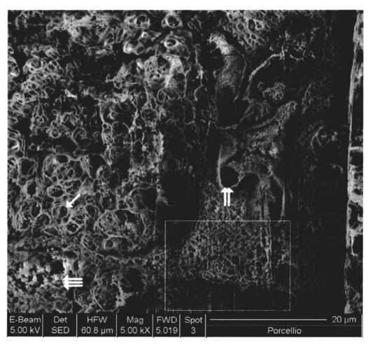
1.IntroductionThe morphology of a biological sample is usually studied by means of three complementary techniques: light microscopy, scanning electron microscopy (SEM), and transmission electron microscopy (TEM). The differences among the three approaches are in the magnification and the 3-D or 2-D imaging. There are some situations in which these traditional methods prove inadequate, for example, simultaneous inspection of gross morphology and ultrastructure, and observation of site-specific subsurface microstructures. These tasks are beyond reach of classical microscopy techniques. In the literature, there are publications indicating the use of a focused ion beam (FIB) system to solve these particular problems.1 2 3 4 5 6 7 Focused ion beam (FIB) systems are increasingly widely used for site-specific 2-D sectioning and imaging of microstructures.8 9 10 The FIB cutting operation is performed by means of high currents, i.e., high ion densities at a very high precision, where at the same time the resulting secondary ions and electrons provide a follow-up sample imaging. The FIB cutting and milling ability represents a method for serial sectioning that, depending on the sample thickness, allows taking sections with spacings in the range from 10 nm to several millimeters between sections. The cross sections are self-aligned and thus are independent of the sample microstructure and do not rely on markers implanted in the sample. No tilts and rotation errors are present.11 It is important to notice that the quality of FIB cuts is not affected by the presence of layers or volumes of material with different thickness or density. Standard techniques request a computer supported 3-D structure reconstruction,12 13 but here a real direct observation of 3-D structures is made available. The consecutive cuts may of course not be parallel, but can also be along any optional planes of the sample. For imaging purposes, the focused ion beam is scanned all over the target surface. Impinging ions transfer their energy to the material surface, which in turn reacts by emitting secondary ions and electrons. These are detected by one of several types of secondary electron and ion detectors currently available. Unlike in the SEM, where the electron probe is just a probe, the scanning ion microscopy (SIM) ion probe is scanned over a sample and destroys it by sputtering, modifying it at a rate determined by the incident beam current and sputter yield of the sample. Due to its destructive interaction, a sample observation has no ad libitum repetitions, as with the SEM. The FIB technique has already been successfully used for biological samples. Young et al.;5 applied for the first time a scanned focused ion beam to prepare biological material. Small defined areas of the cuticular surface of mites were removed by ion etching to allow examination of the underlying structures. The first documentation of a successful application of the FIB for in situ sample preparation and microscopy of cells is the work of Ballerini et al.;1 A comparison of the performances of a FIB machine, TEM, SEM,14 and soft x-ray contact microscopy (SXCM)8 15 16 17 18 is presented by Milani et al.;19 Up to now, the FIB operation was done on Saccharomyces cerevisiae, Candida albicans, mites of the genus Halarachne, bacteria, human chondrocytes, lymphocytes, oocytes, and on a single gut epithelial cell.1 2 3 4 5 6 7 20 21 Although the authors pointed out many advantages of the use of the FIB in biomedicine, up to now no experimental data existed on the in situ sample preparation and application of the SIM and/or SEM to gross morphology and cell ultrastructure inspection of the very same sample. We selected the digestive system of the terrestrial isopod crustacean Porcellio scaber (isopoda, crustacea) as a test system, where we studied the application of the FIB for microscopy and for in situ sample preparation. The terrestrial isopod P. scaber is one of the most studied organisms in terrestrial ecophysiology and ecotoxicology.22 23 It is also an organism of choice in comparative morphological studies of adaptation to life on land.24 The digestive system of P. scaber consists of a short stomach, a gut, and two pairs of tube shaped digestive glands (hepatopancreas). It was thoroughly studied by means of light microscopy, scanning, and transmission electron microscopy (Fig. 1).25 Figure 1Drawing of the digestive system of P. scaber. G is gut, H is one of four tubes of hepatopancreas, and S is stomach. 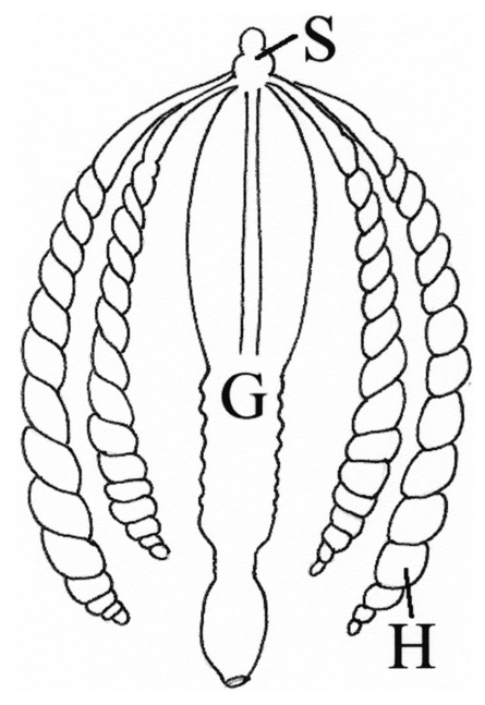 The aim of our work was to use the FIB for microscopy and as an in situ cutting device on the very same biological sample, the digestive system of a terrestrial isopod P. scaber. No significant differences in the SIM and SEM imaging of the gross morphology were expected. The imaging was used to navigate around the specimen and to choose an area to be milled. The localized milling exposed ultrastructural features for subsequent SEM or SIM imaging. We expected that the in situ FIB operations would be a tool for an actual 3-D cellular structure examination that could not be reached by other microscopic techniques. 2.Materials and MethodsTerrestrial isopods, Porcellio scaber, were collected under concrete blocks and pieces of decaying wood. For histological observation, digestive glands (hepatopancreas) were fixed in Carnoy-B fixative for 2 h at room temperature, dehydrated in ethanol series, and subsequently embedded in paraplast. 8-μm sections were stained with hematoxylin-eosin. For studies with the FIB, the entire digestive system of P. scaber was isolated and fixed in 1.5 glutaraldehyde and 1.0 paraformaldehyde in 1.5-M cocadilate sodium cacodylate buffer (pH 7.2) for 2.5 h at room temperature. After dehydration in a graded series of ethanols, the digestive system was dried at the critical point. The sample was placed on a silicon wafer holder (5 cm diam, 6-axis eucentric stage) and scanned with a focused ion beam (FEI Strata DB 235 M dual beam, Modena University). The currents for imaging were in the range of 10 pA, while the currents for cutting were up to 20 nA. The system operated with column pressures in the 10−5 Pa range with the work chamber between 10−4 to 10−3 Pa. The FIB machine also allowed metal deposition (platinum) that was used both for sample coating, as it is required in the SEM imaging, and for improving the cutting performances of the ion beam, while preventing excess charging of the sample when no electron flood gun is available, as in our case. The spot size was as low as 3 to 5 nm in diameter. Along with the FIB imaging, the SEM was performed by means of the electron column available in the same machine. 3.ResultsDetailed knowledge of the anatomy, histology, and ultrastructure of the digestive system of P. scaber gained from previous works was the basis for interpreting the results obtained by means of the FIB application. The digestive system of P. scaber is composed of a short stomach, four blind ending gland tubes of the digestive glands (hepatopancreas), and a gut (Fig. 1). The three parts are connected in the cephalothorax (Figs. 1 and 2). The hepatopancreas is attached to the stomach via lateral ducts (Figs. 1 and 2) and surrounded by a network of muscles (Fig. 3). Figure 2 is an ion beam image of the digestive system gross morphology. Figure 3 is an electron beam image of a platinum-coated digestive gland. Two types of cells have been described in the hepatopancreatic tissue [Figs. 4(a) and 4(b)]. Large B cells project into the lumen of the hepatopancreas, and small conoidal S cells lie among the B cells.24 Figure 2FIB micrograph of the ventral part of the digestive system with a junction among hepatopancreas, stomach, and gut (uncoated sample). G is gut, H1 and H2 are two tubes of hepatopancreas, S is stomach, LD is the lateral duct connecting the stomach with the hepatopancreas, N is nerve, M is the thick muscular layer in the region of the stomach, one arrow is the basal part of cells forming the atrium, and two arrows are nerve fibers pulled out of the ganglion. 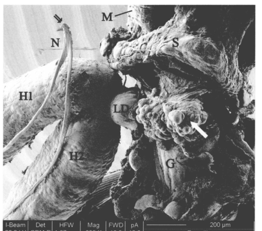 Figure 3Scanning electron micrograph of the outer surface of hepatopancreas (Pt coated sample). M is muscular network surrounding the gland tube. Basal parts of those cells were cut out by FIB. The position of the FIB cut imaged in Fig. 5 is shown by a line.  Figure 4(a) Light micrograph of the cross section of the gland tube. B is a big cell, S is a small cell, Nu is nucleus, L is gland lumen, and Lp are lipids in B cells. Arrows indicate the space between two B cells. The approximate position of the FIB cut is shown by the dotted line. (b) Electron micrograph of a mechanically broken digestive gland tube. The exposed surface is gold coated. The square indicates the FIB milled region shown on Fig. 8. The dotted line shows the approximate position of the FIB cut. The arrow indicates an area where lipids were originally deposited.  Figure 5A deeper FIB cut and scanning electron imaging of the same region of sample shown in Fig. 5. One arrow points out a round-shaped empty hole where lipids were originally deposited, two arrows indicate the microvillous border facing the lumen of the gland, and three arrows show metal granules. The square denotes a region of densely knitted fibers magnified and presented in Fig. 7.  Figure 7FIB cut and scanning electron imaging of the basal part of a B cell indicated in Fig. 6. Note the same magnification of the basal part of a B cell on this image and the apical part of a B cell in Fig. 8.  Figure 8FIB cut and scanning electron imaging of the apical part of a B cell indicated in Fig. 4(b). M is microvilli, and Lp are lipids. 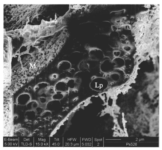 The FIB cut of the basal part of the gland epithelium reveals basal parts of B and S cells (Fig. 5). The space among cells can clearly be seen. Round-shaped empty holes of a few micrometers in size can be interpreted as the areas where lipids were originally deposited, and which were washed out by alcohols during the preparation procedure [Figs. 4(a), 4(b), 5 and 6] A higher magnification of the FIB milled basal parts of cells is shown in Figs. 6 and 7. The milling plane came near the gland lumen: the microvillous lumenal border and knitted fine filamentous cell structures can be observed (Fig. 6). Regions with looser and denser knitted structures can be distinguished. Regions with regular granules of the same size (Fig. 6) are most likely metal granules in the S cells, which are not found in B cells. Figure 7 shows higher magnification of basal parts of the cells with dense knitted fine filamentous structures. The milling of the apical part of a B cell [Fig. 8, milled region marked on Fig. 4(b)] revealed different structural integrity from that of the basal part. Apical parts of the B cell are filled with homogenous material. Again, larger holes can be interpreted as areas where lipids were originally deposited. 4.DiscussionWe proved that a FIB machine can be used as a microscope and as an in situ cutting device for tissue and cells. For the first time we obtained ion images of different animal tissues both from uncoated and coated samples. The quality of the images on the gross morphology of the investigated digestive system is the same as that obtained on similar samples with the SEM.26 The advantage of ion imaging is that we can observe uncoated samples by reducing the surface charging effects if the electron and ion beams are alternatively used, as it was in our case (or when the electron flood gun is available). The disadvantage of ion imaging is the lower resolution in comparison with electron imaging. In cases where coating or metal postfixation during the preparation is not suggested, ion imaging is the better option. The major advantage of a FIB machine in life sciences is its ability of in situ sample preparation and subsequent imaging, along any selected section plane. The ion beam cutting operation is interactive with imaging, namely the section plane can be selected according to the results of intermediate observations (imaging). Using the FIB for operations equivalent to serial sectioning, the sample sections could be cut at a sequence depth down to 10 nm, dictated by the focusing ability and control of the ion beam. This is apparently a great advantage when compared to the SEM, where internal structures are exposed by random fracturing or cutting and thus the in situ sample manipulation is not possible. After the cutting operation, some of the ultrastructural elements of hepatopancreas could clearly be recognized. In particular, metal granules in S cells and round-shaped empty holes that correspond to lipids in B cells could be identified, and a network of dense and loose fibrous structures was visible. Moreover, the FIB operation revealed significant differences in structural integrity between the apical and basal parts of the hepatopancreatic cells. The basal parts of both cell types were filled with knitted fine filamentous structures, while the apical parts of the same B cells were filled with homogenous material. This is in accordance with the excretory function of B cells: however, structural differences of this type have not been described.22 The interaction of the energetic ions of the FIB with the target material can be prone to generate artifacts. A potential problem with the FIB section could be the implantation of gallium ions into the section. The presence of thin amorphous layers on the surfaces cannot be excluded on our images. An additional problem with the FIB sections is the redeposition of the sputtered material. There are reports in the literature that none of these effects generate significant artifacts.10 A comparison between a FIB and ultramicrotome section revealed that the region was less affected by the FIB operation. In our work, the structural integrity of a FIB processed sample was compared to that in a mechanically broken sample just before the FIB milling. However, additional work is necessary to identify fully the level and type of artifacts present in the FIB sections. Our results obtained by means of the FIB/SEM and in situ sample preparation have been validated by a comparison with the reference to the established microscopy techniques.22 25 27 However, a direct comparison of cell ultrastructure analyses obtained with TEM and FIB/SEM is not possible because of differences in the approaches. For TEM images of P. scaber hepatopancreas, the reader should refer to the work by Zˇnidarsˇicˇ, Sˇtrus, and Drobne. The FIB microscopy with the in situ sample preparation for actual 3-D imaging is in the early stage of application for biological samples, and appears to be a technique of choice for 3-D observations at the organism, organ, tissue, and (sub)cellular level. 5.ConclusionsFor the first time, we obtain ion images of different animal tissues both from uncoated and coated samples. The in situ FIB operations reveal characteristics of structural integrity of cells that could not be reached by other microscopy techniques. We conclude that FIB microscopy and in situ sample preparation have the following advantages over classical microscopy techniques: AcknowledgmentsWe would like to thank Stefano Frabboni for providing access and assistance to the FIB facilities at INFM-Modena, and Jasna Sˇtrus for valuable discussions. The cooperation among authors of this work was supported by the Italian Ministry for Foreign Affairs and the Slovenian Ministry of Education, Science and Sport (grant SLO-ITA 10M/2002–2005). REFERENCES
M. Ballerini
,
M. Milani
,
M. Costato
,
F. Squadrini
, and
I. C. E. Turcu
,
“Life science applications of focused ion beams (FIB),”
Eur. J. Histochem. , 41 89
–90
(1997). Google Scholar
M. Ballerini
,
M. Milani
,
D. Batani
, and
F. Squadrini
,
“Focused ion beam techniques for the analysis of biological samples: A revolution in ultramicroscopy?,”
Proc. SPIE , 4261 92
–104
(2001). Google Scholar
H. Moulders
,
“The use of a SEM/FIB dual beam applied to biological samples,”
G.I.T. Imag. Microscopy , 2 8
–10
(2003). Google Scholar
R. J. Young
,
T. Dingle
,
K. Robinson
, and
P. J. A. Pugh
,
“An application of scanned focused ion beam milling to studies on the internal morphology of small arthropods,”
J. Microsc. , 172 81
–88
(1993). Google Scholar
R. A. D. Mackenzie
and
G. D. W. Smith
,
“Focused ion beam technology: a bibliography,”
Nanotechnology , 1 163
–201
(1990). Google Scholar
D. Mavrocordatos
,
M. Steiner
, and
M. Boller
,
“Analytical electron microscopy and focused ion beam: complementary tool for the imaging of copper sorption onto iron oxide aggregates,”
J. Microsc. , 210 45
–52
(2003). Google Scholar
B. J. Inkson
,
T. Steer
,
G. Mo¨bus
, and
T. Wagner
,
“Subsurface nanoindentation deformation of Cu-Al multilayers mapped in 3D by focused ion beam microscopy,”
J. Microsc. , 201 256
–269
(2001). Google Scholar
R. Haswell
,
D. W. McComb
, and
W. Smith
,
“Preparation of site-specific cross-sections of heterogeneous catalysts prepared by focused ion beam milling,”
J. Microsc. , 211 161
–166
(2003). Google Scholar
J. Alkemper
and
P. W. Voorhees
,
“Quantitative serial sectioning analysis,”
J. Microsc. , 201 388
–394
(2001). Google Scholar
T. R. Matzelle
,
N. Kruse
, and
R. Reichelt
,
“Characterization of the cutting edge of glass knives for ultramicrotomy by scanning force microscopy using cantilevers with a defined tip geometry,”
J. Microsc. , 199 239
–243
(2000). Google Scholar
B. S. Duerstok
,
C. L. Bajaj
, and
R. B. Borgens
,
“A comparative study of the quantitative accuracy of three-dimensional reconstructions of spinal cord from serial histological sections,”
J. Microsc. , 210 138
–148
(2003). Google Scholar
H. Kondo
and
T. Tomie
,
“Optimization of a laser-plasma x-ray source for contact x-ray microscopy,”
J. Appl. Phys. , 75 3798
–3805
(1994). Google Scholar
D. Batani
,
C. Botto
,
F. Bortolotto
,
A. Masini
,
A. Bernardinello
,
M. Moret
,
M. Milani
,
G. Poletti
,
F. Cotelli
,
C. Lora Lamia Donin
,
S. Piccoli
,
A. Stead
,
T. Ford
,
A. Marranca
,
K. Eidmann
,
F. Flora
,
L. Palladino
, and
L. Reali
,
“Contact x-ray microscopy using the asterix laser source,”
Physica Medica , 16 49
–55
(1999). Google Scholar
J. Maser
,
A. Osanna
,
Y. Wang
,
C. Jacobsen
,
J. Kirz
,
S. Spector
,
B. Winn
, and
D. Tennant
,
“Soft x-ray microscopy with a cryo scanning transmission x-ray microscope: I—Instrumentation, imaging and spectroscopy,”
J. Microsc. , 197 68
–79
(2000). Google Scholar
Y. Wang
,
C. Jacobsen
,
A. Osanna
, and
J. Maser
,
“Soft X-ray microscopy with a cryo scanning transmission x-ray microscope: II—Tomography,”
J. Microsc. , 197 80
–93
(2000). Google Scholar
M. Ballerini
,
M. Milani
,
M. Costato
,
I. C. E. Turcu
, and
F. Squadrini
,
“Focused ion beams and life science applications: cell tomography and biomachining at ultrahigh resolution,”
Proc. SPIE , 3260 221
–231
(1998). Google Scholar
M. Ballerini
and
M. Milani
,
“Ion beam machines in life sciences,”
Laser Technol. , 12 26
–37
(2002). Google Scholar
D. Drobne
,
“Terrestrial isopods—a good choice for toxicity testing of pollutants in the terrestrial environment,”
Environ. Toxicol. Chem. , 16 1159
–1164
(1997). Google Scholar
M. Zimmer
,
“Nutrition in terrestrial isopods (Isopoda: Oniscidea): an evolutionary ecological approach,”
Biol. Rev. , 77 455
–493
(2002). Google Scholar
N. Zˇnidarsˇicˇ
,
J. Sˇtrus
, and
D. Drobne
,
“Ultrastructural alterations of the hepatopancreas in Porcellio scaber under stress,”
Environ. Toxicol. Pharmacology , 13 161
–174
(2003). Google Scholar
|