
|
|
1.IntroductionSince the introduction of optical coherence tomography (OCT) to imaging biological tissue more than a decade ago,1 the technique has developed rapidly. Overviews of this technique can be found, for example, in Refs. 2, 3. Imaging ocular tissues still represents the main field of application of OCT. Up to now, several papers have shown the value of this technique for imaging retinal pathologies.4, 5, 6 Initiated by the discovery of a sensitivity advantage of Fourier domain (FD-) or spectral domain (SD-) OCT compared to standard time domain (TD-) OCT,7, 8, 9 high speed image acquisition has been demonstrated. Especially the decoupling of image acquisition speed from depth resolution enabled three-dimensional (3D) ultrahigh resolution imaging of the human retina in vivo.10 Still some limitations are present in this technique, such as sensitivity decay with depth or motion artifacts in en-face images reconstructed from a 3D data set. However, the advantage of acquiring a single A scan simultaneously (with one shot) turns out to be a drawback of SD-OCT when a high transverse resolution that is constant with depth is needed. This limitation could be of major importance if adaptive optics (AO) are combined with OCT. Here the transverse resolution is close to the diffraction limited resolution and, therefore, the depth of focus is only some tens of micrometers.11, 12 In this case, the desired resolution is achieved in only a very thin layer of the OCT image. To overcome this problem, several data sets with different focus positions have to be recorded. From this data, sharp en-face images could be extracted but this procedure increases the measurement time enormously. A dynamic shift of focus seems only possible for TD-OCT systems where different sample depths are probed at different instants. Several methods have been introduced to realize a dynamic focus in A scan (or depth scan priority) based systems. One technique uses a scanning method in which focusing lens and a retro reflector are mounted together on a common translation stage.13 However, this method is limited to low imaging speeds due to the inertia of shifting the lens and the retro reflector during each A scan. Furthermore, a refractive index equal to of the investigated tissue is necessary for a correct shift of focus. Another method proposes a dynamic focus shift without changing the path length in the corresponding interferometer arm.14 This method allows rapid A scans at ; however, it is very restricted with respect to sample geometry and therefore not suitable for retinal imaging. Recently, new techniques were developed to achieve a dynamic focus at higher imaging speeds. One technique uses a microelectromechanical mirror to increase the focusing power of the object lens that enables a fast shift of focus.15 Another technique was especially designed for endoscopic applications.16 Since none of these techniques mentioned above can directly be used in the in vivo retina, retinal OCT with high transverse resolution throughout the depth of retinal tissue is still a major technical challenge. In this paper, we present a fast TD-OCT technique for retinal imaging based on a transversal scanning of the sample,17, 18 which solves this problem. We show that maintaining transverse resolution can be achieved in a model eye. Furthermore, we demonstrate the dynamic focus technique, to the best of our knowledge for the first time, for imaging human retina in vivo. With the proposed method, en-face OCT images of the lamina cribrosa could be recorded. 2.ExperimentThe scheme of the basic OCT system is published elsewhere.19 In brief, the setup is based on a Mach Zehnder interferometer [cf. Fig. 1a ] and on a fast transverse scanning of the sample (scan velocity in transverse scan velocity). Two acousto-optic modulators placed in the reference arm generate a net frequency shift of the reference beam of , equal to the carrier frequency. A path delay unit in the reference arm, which is mounted on a translation stage, enables scanning of the coherence gate through the sample depth ( direction). The scanning optics in the sample arm of the device [cf. Fig. 1b] consists of two galvoscanners ( directions) and a telescope to generate a collimated beam incident on the cornea and to image the pivot point of one scanner onto the pupil plane of the eye. [For the sake of simplicity, the galvoscanner was omitted in Fig. 1b]. The second lens (L2) of the telescope is mounted on a translation stage (dynamic focus) and can be moved along the optic axis simultaneously to the reference translation stage for depth scanning. Since the two translation stages are moved with different velocities, no direct link between the stages was implemented. The moment of start of the two stages was triggered and each motor followed a predetermined velocity profile. The beam incident on the scanning optics is collimated with a beam diameter of . The focal lengths of the lenses are (L1) and (L2), respectively. This configuration reduced the beam diameter of the beam incident onto the cornea to . The scanner of the system is driven at a frequency of , which enables a line rate of . The instrument can be either operated in a B-scan imaging mode ( plane) or in an en-face scan imaging mode ( plane). A B-scan image (or an en-face image) consisting of is recorded in . A superluminescent diode (SLD) (Superlumdiodes Ltd., Russia) with a center wavelength of and a full width at half maximum (FWHM) bandwidth of was used in the system. This results in a theoretical depth resolution of within the retina (assuming a refractive index of 1.38 of the retina). The power incident on the cornea was measured with . The following safety considerations show that this power is safe for our scanning scheme according to standards of the American National Standards Institute (ANSI).20 Due to the very fast scanning of the probing beam over the retina, each measurement point on the retina is repeatedly illuminated for a very short time. Therefore the illumination can be regarded as an illumination with a pulsed light source. The pulse duration (illumination time at a certain location) varies within a transverse line because a sinusoidal scanning pattern is used. The most critical positions are the turning points of the scanner where the exposure time at this location is maximum. With the assumption of a scanning angle of , which corresponds to a distance of on the retina and an illumination spot diameter of (here we included possible aberrations of the eye that increase the pulse duration), the longest pulse duration can be calculated with with a repetition time of . According to ANSI standards, three rules are applicable for repeated exposures to calculate the maximum permissible power (MPP) incident on the cornea. First, the exposure of a single pulse shall not exceed the maximum permissible exposure (MPE) for a single pulse of that pulse duration. For the longest pulse duration, we calculated a MPP of . Second, the average power delivered in measurement time shall not exceed the MPE for this exposure time. For this rule, we considered the MPE for continuous viewing and calculated a MPP of for the used “pulsed” source. The third rule accounts for subthreshold pulse cumulative thermal injury. For a measurement time of , we calculated a MPP of . An alternative way to evaluate the MPP for a rapidly transversally scanning beam is to treat the beam as emitted by an extended light source.20 The calculation provides a MPP of if we treat the fast scanning beam as an extended cw light source. All of these different calculations show that the used power incident on the cornea is well below the lowest MPP value. Note that eye movements will enlarge the illuminated area, and therefore, the thermal energy is spread over a larger area. Fig. 1(a) Scheme of the experimental setup: LS—light source; SLO—scanning laser ophthalmoscope detector; D1 and D2 OCT detectors; AOM—acousto-optic modulator. (b) Scanning optics: S—galvanometer scanner; L1—fixed lens with focal length ; L2—movable lens with focal length ; RE—reduced eye model; ne—refractive index of reduced eye.  Since the Mach Zehnder interferometer enables access to both interferometer exits (both interferometric signals are shifted by . with respect to each other), balanced detection can easily be achieved. We used a balanced receiver (FEMTO-HCA-S) to detect the light exiting both exits. A part of the light backscattered from the retina was not brought to interference with the reference arm but was used to record scanning laser ophthalmoscope (SLO) images [cf. Fig. 1a], similar to previously reported en-face OCT imaging systems.21 3.Theoretical ConsiderationsThe FWHM focus spot diameter (assuming diffraction limit) ( intensity radius) of the beam on the retina was calculated with ( beam diameter, ). Depth of focus (DOF) increases quadratically with focus spot size diameter and was calculated with . A shift in the position of L2 introduces a shift of focus position within the retina. Paraxial matrix methods were used to calculate this shift of focus.22 For this calculation, we first assume a fixed galvoscanner position. To further simplify the calculations, we used a reduced eye model in which the refractive elements of the eye are replaced by a single curved interface (radius ) and a mean refractive index of the eye.23 If the distance between lenses L1 and L2 matches exactly the sum of the focal lengths f1 and f2 (zero position), then a distance of between the position of the focus and the surface of the cornea was calculated that corresponds to results obtained in Ref. 23. Figure 2 shows the calculated dependence of the shift of focus position from zero position with displacement of L2 in both directions. The dependence is approximately linear, with a factor of between L2 shift and focus shift. If L2 is moved four times faster than the coherence gate, the residual tracking error is below , which is well within the DOF. 4.Results4.1.Model Eye and Resolution Test TargetTo test the performance of our system, we recorded several images of a resolution test target (RTT) (Melles Griot-USAF-1951 chromium positive) in a model eye (Eyetech Ltd., Laser Model Eye LE-110) filled with water. The model eye consists of cornea, iris, lens, and retina. For this experiment, the retina was replaced by the RTT. Figure 3 shows a scheme of the adapted model eye. The RTT was mounted on a translation stage that enabled a precise depth positioning of the RTT with micron resolution. In a first measurement, the lens L2 was exactly placed into a position that generated a collimated beam exiting L2 (distance between L1 and L2). The RTT was placed in the position of the focus (position 1 in Fig. 3). In this configuration (without dynamic focus), we recorded a 3D data set consisting of 10 en-face OCT and 10 SLO images each. The images were recorded at depth increments (of the coherence gate) of , the total scanning depth of this data set was with a scanning angle in the and directions of (corresponding to distance on the RTT). Figure 4a shows the entire SLO image of the RTT that corresponds to the focal plane (i.e., central image of the 3D data stack). For a better visualization of the resolution, we enlarged the central part of the image. The result is shown in Fig. 4b. The corresponding en-face OCT image is shown in Fig. 4c. Element 6 of group 6 (corresponding to or resolution) is clearly resolvable in both the SLO and OCT images. This is only slightly worse than the calculation of the diffraction limited case, probably caused by aberrations of the model eye optics. Note that the resolution in the direction is lower than in the direction. This effect is more pronounced in the SLO image. The reason is as follows: the direction is the priority scan direction, that is, the direction along which the scanning beam advances fastest. Small structures along this direction cause high imaging frequencies (we calculated a maximum frequency of for a resolution of ). The cutoff frequencies of detector and amplifier electronics ( for the OCT channel and for the SLO channel) are lower than the frequency corresponding to the smallest structure, causing a slight image blurring (which is more pronounced in the SLO channel) in the direction, which is associated with a loss of resolution. Fig. 3Scheme of the model eye: C—cornea; I∕L—iris with lens; RTT—resolution test target; TS—translation stage. (The numbers indicate the different positions of the RTT in respect to the focal plane: 1 in focus, 2 and 3 off focus.) 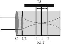 Fig. 4SLO and en-face OCT images of the resolution test target. (a) SLO image of RTT in focus; (b) enlarged section of (a); (c) OCT image of RTT in focus; (d) and (e) SLO and OCT image of RTT off focus (dynamic focus switched off); (f) and (g) SLO and OCT image of RTT off focus (dynamic focus switched on); (h) and (i) SLO and OCT image of RTT off focus (dynamic focus switched off); (j) and (k) SLO and OCT image of RTT off focus (dynamic focus switched on).  This is not a general limitation but specific to our detection electronics, and compared to the loss of resolution because of defocus, this effect is negligible as will be shown later. In a next step, the position of the RTT was shifted by an optical distance of from zero position (position 2 in Fig. 3). The coherence gate of the OCT system was used to precisely determine this distance. Another 3D data set was recorded. Figures 4d and 4e show SLO and OCT images obtained from the 3D data set at a coherence gate position of . As expected (since the dynamic focus is still switched off, the focus position remains at 0), both images lost their sharpness and resolution is degraded enormously. Figures 4f and 4g show SLO and OCT images of the RTT at the same position but with the dynamic focus switched on (L2 is moved simultaneously to the coherence gate depth scan). A similar resolution as in Figs. 4b and 4c can be observed. To test the performance over the whole depth scan, we moved the RTT to the position from the zero position (position 3 in Fig. 3) and recorded 3D data sets with and without dynamic focus. The result is shown in Figs. 4h and 4i (without dynamic focus) and Figs. 4j and 4k (with dynamic focus), respectively. Equivalent results are obtained as for the position. 4.2.Human RetinaIn a next step, we recorded images of the retina of a healthy human volunteer in vivo. During positioning of the subject, a real-time display mode of en-face OCT and SLO images (at ) enabled a fast adjustment of the focal position within the retina. In the SLO image, structures within the focal plane appear brightest. After adjusting the focal plane to a suitable feature within the retina, the coherence gate was adjusted to match the focal plane of the SLO image (recognized by lighting up of the feature in focus). This step is crucial to finding the correct starting position for the dynamic focus. In the case of a mismatch, the whole OCT image would appear blurred. An influence of autofocusing of the eye on the measurement can be neglected here. There is no vision of the subject in the investigated region of the optic nerve head, and therefore, the subject has to fixate a target located at a certain angle to the probing beam and at a fixed distance. (In this experiment, the contralateral eye was used for fixation). Figure 5 shows B-scan images of the nerve head region without and with dynamic focus. The loss of signal intensity with depth because of defocus is clearly visible in Fig. 5a. Here the focal plane was placed within the retina on the nasal side [indicated by an arrow in Fig. 5a]. On the other hand, the signal intensity is maintained in Fig. 5b (with dynamic focus). Furthermore, if we compare the region of the lamina cribrosa, the image appears sharper and more details can be observed in Fig. 5b compared to Fig. 5a. The slight mismatch of signal intensity in the retinal nerve fiber region in the left hand side of the image is probably caused by blocking of a fraction of the incoming light beam by the iris during recording of Fig. 5b. Fig. 5Images of the nerve head region: (a) without dynamic focus (arrow indicates the focus position), (b) with dynamic focus.  The major advantage of our setup is the possibility to record en-face images with high speed and resolution. The structure of the lamina cribrosa is postulated to play an important role in glaucoma.24, 25 However, currently available techniques offer either high depth resolution (OCT) or high transverse resolution (SLO) of this region, but are not able to provide high axial and transverse resolution simultaneously. This prevented detailed imaging of the lamina’s sievelike structure and the evolution of its pores with depth up to now. Since our technique achieves approximately isotropic high resolution in all three spatial dimensions, en-face sections of the lamina in different depths can be recorded. Figure 6 shows 10 en-face images obtained at different depths ( apart from each other; closer sectioning intervals are, of course, possible with either larger recording time or faster scanning speed, e.g., by the use of resonant scanners18) of the lamina cribrosa with the highest transversal resolution imaged with OCT so far. Clearly visible is the sievelike structure of the lamina. SLO images of this region can also show the sievelike structure, however, only in a depth integrated manner (integration over depth).24 Access to the 3D structure was—up to now—only possible by in vitro imaging of casts.25 A comparison with these histological images clearly demonstrates the good image quality of our results, which show similar structures in vivo. The knowledge of the exact anatomy of the lamina cribrosa might be useful to investigate the role of this structure in maintaining the integrity of axonal processes25, 26 and to investigate the influence of ocular diseases, such as glaucoma,27 on this structure. 5.Discussion and ConclusionWe demonstrated, to the best of our knowledge, for the first time, dynamic focusing in retinal OCT imaging. The maintenance of high transversal resolution with depth was proven in a model eye. In vivo images with high transversal resolution of a normal human retina were presented. However, aberrations of a real eye will reduce resolution that can actually be achieved within the retina. The actual resolution in a real retina might be quantified by looking for the smallest resolvable structures. On the other hand, AO can be used to correct for these aberrations and a diffraction limited resolution might then be achieved. Our transversal scanning approach with dynamic focusing seems to be especially suited for combining AO with OCT, because it should enable a constant resolution within the whole 3D volume, throughout the imaging depth. A minor drawback of our method, however, is the change of the field of view introduced by movement of the lens L2. This corresponds to a distortion of the wavefront (the pivot point of the scanner is not imaged into the pupil plane), which distorts the image geometry. For the maximum scanning angle, we calculated a change of of the field of view (transverse image size) for an imaging depth of . A similar distortion of 4% of the image depth was calculated for the maximum scanning angle and seems therefore to be negligible. Since the discovery of the sensitivity advantage of SD-OCT compared to TD-OCT7, 8, 9 TD-OCT systems are frequently regarded as out of date. However, our results show that there is still an application field for special TD-OCT systems. The fact that information on different sampling depths is recorded subsequently by TD-OCT, turns out to be an advantage if high transverse resolution is to be maintained throughout a larger imaging depth. The rather slow progression of the coherence gate in depth with transversal scanning systems makes them especially suited for dynamic focusing because the mechanical demands on focus tracking are alleviated. The sensitivity advantage of SD-OCT systems is partly compensated by two reasons: (i) The full sensitivity advantage of SD-OCT is only maintained over a rather shallow depth range of a few . Over larger depths, there is a sensitivity decay of typically .28, 29, 30 TD-OCT, on the other hand, has a constant sensitivity with depth. (ii) Dynamic focusing allows us to concentrate the available light power into the imaged depth, thus increasing the power that is backscattered from in-focus structures. This confocal effect increases the sensitivity of dynamic focused TD-OCT systems [cf. Fig. 5b]. Therefore, we think that there will be a coexistence of high speed SD-OCT systems and high transverse resolution TD-OCT systems. AcknowledgmentsThe authors wish to thank H. Sattman for technical assistance. Financial assistance from the Austrian Fonds zur Förderung der wissenschaftlichen Forschung (FWF Grant No. P16776-N02) is acknowledged. ReferencesD. Huang,
E. A. Swanson,
C. P. Lin,
J. S. Schuman,
W. G. Stinson,
W. Chang,
M. R. Hee,
T. Flotte,
K. Gregory,
C. A. Puliafito, and
J. G. Fujimoto,
“Optical coherence tomography,”
Science, 254 1178
–1181
(1991). 0036-8075 Google Scholar
B. E. Bouma and
G. J. Tearney, Handbook of Optical Coherence Tomography, Marcel Dekker, New York
(2002). Google Scholar
A. F. Fercher and
C. K. Hitzenberger,
“Optical coherence tomography,”
Prog. Opt., 44 215
–302
(2002). 0079-6638 Google Scholar
C. A. Puliafito,
M. R. Hee,
C. P. Lin,
E. Reichel,
J. S. Schuman,
J. S. Duker,
J. A. Izatt,
E. A. Swanson, and
J. G. Fujimoto,
“Imaging of macular diseases with optical coherence tomography,”
Ophthalmology, 102 217
–229
(1995). 0161-6420 Google Scholar
P. Massin,
C. Allouch,
B. Haouchine,
F. Metge,
M. Paques,
L. Tangui,
A. Erginay, and
A. Gaudric,
“Optical coherence tomography of idiopathic maclular epiretinal membranes before and after surgery,”
Am. J. Ophthalmol., 130 732
–739
(2000). https://doi.org/10.1016/S0002-9394(00)00574-2 0002-9394 Google Scholar
W. Drexler,
H. Sattmann,
B. Hermann,
T. H. Ko,
M. Stur,
A. Unterhuber,
C. Scholda,
O. Findl,
M. Wirtitsch,
J. G. Fujimoto, and
A. F. Fercher,
“Enhanced visualization of macular pathology with use of ultrahigh-resolution optical coherence tomography,”
Arch. Ophthalmol. (Chicago), 121 695
–706
(2003). https://doi.org/10.1001/archopht.121.5.695 0003-9950 Google Scholar
R. A. Leitgeb,
C. K. Hitzenberger, and
A. F. Fercher,
“Performance of Fourier domain vs. time domain optical coherence tomography,”
Opt. Express, 11 889
–894
(2003). 1094-4087 Google Scholar
J. F. de Boer,
B. Cense,
B. H. Park,
M. C. Pierce,
G. J. Tearney, and
B. E. Bouma,
“Improved signal-to-noise ratio in spectral-domain compared with time-domain optical coherence tomography,”
Opt. Lett., 28 2067
–2069
(2003). 0146-9592 Google Scholar
M. A. Choma,
M. V. Sarunic,
C. Yang, and
J. A. Izatt,
“Sensitivity advantage of swept source and Fourier domain optical coherence tomography,”
Opt. Express, 11 2183
–2189
(2003). 1094-4087 Google Scholar
B. Cense,
N. A. Nassif,
T. C. Chen,
M. C. Pierce,
S.-H. Yun,
B. H. Park,
B. E. Bouma,
G. J. Tearney, and
J. F. de Boer,
“Ultrahigh-resolution high-speed retinal imaging using spectral-domain optical coherence tomography,”
Opt. Express, 12 2435
–2447
(2004). https://doi.org/10.1364/OPEX.12.002435 1094-4087 Google Scholar
B. Hermann,
E. J. Fernández,
A. Unterhuber,
H. Sattmann,
A. F. Fercher,
W. Drexler,
P. M. Prieto, and
P. Artal,
“Adaptive-optics ultrahigh-resolution optical coherence tomography,”
Opt. Lett., 29 2142
–2144
(2004). https://doi.org/10.1364/OL.29.002142 0146-9592 Google Scholar
Y. Zhang,
J. Rha,
R. S. Jonnal, and
D. T. Miller,
“Adaptive optics parallel spectral domain optical coherence tomography for imaging the living retina,”
Opt. Express, 13 4792
–4811
(2005). https://doi.org/10.1364/OPEX.13.004792 1094-4087 Google Scholar
J. M. Schmitt,
S. L. Lee, and
K. M. Yung,
“An optical coherence microscope with enhanced resolving power in thick tissue,”
Opt. Commun., 142 203
–207
(1997). https://doi.org/10.1016/S0030-4018(97)00280-0 0030-4018 Google Scholar
F. Lexer,
C. K. Hitzenberger,
W. Drexler,
S. Molebny,
H. Sattmann,
M. Sticker, and
A. F. Fercher,
“Dynamic coherent focus OCT with depth-independent transversal resolution,”
J. Mod. Opt., 46 541
–553
(1999). https://doi.org/10.1080/095003499149845 0950-0340 Google Scholar
B. Qi,
A. P. Himmer,
L. M. Gordon,
V. X. D. Yang,
L. D. Dickensheets, and
I. A. Vitkin,
“Dynamic focus control in high-speed optical coherence tomography based on a microelectromechanical mirror,”
Opt. Commun., 232 123
–128
(2004). https://doi.org/10.1016/j.optcom.2004.01.015 0030-4018 Google Scholar
M. J. Cobb,
X. Liu, and
X. Li,
“Continuous focus tracking for real-time optical coherence tomography,”
Opt. Lett., 30 1680
–1682
(2005). https://doi.org/10.1364/OL.30.001680 0146-9592 Google Scholar
A. G. Podoleanu,
G. M. Dobre, and
D. A. Jackson,
“En-face coherence imaging using galvanometer scanner modulation,”
Opt. Lett., 23 147
–149
(1998). 0146-9592 Google Scholar
C. K. Hitzenberger,
P. Trost,
P. W. Lo, and
Q. Zhou,
“Three-dimensional imaging of the human retina by high-speed optical coherence tomography,”
Opt. Express, 11 2753
–2761
(2003). 1094-4087 Google Scholar
M. Pircher,
E. Götzinger,
R. Leitgeb, and
C. K. Hitzenberger,
“Transversal phase resolved polarization sensitive optical coherence tomography,”
Phys. Med. Biol., 49 1257
–1263
(2004). https://doi.org/10.1088/0031-9155/49/7/013 0031-9155 Google Scholar
American National Standards Institute,
“American National Standard for Safe Use of Lasers,”
45
–49 Laser Institute of America,
(2000). Google Scholar
A. G. Podoleanu and
D. A. Jackson,
“Noise analysis of a combined optical coherence tomograph and a confocal scanning ophthalmoscope,”
Appl. Opt., 38 2116
–2127
(1999). 0003-6935 Google Scholar
M. Brass,
E. W. Van Stryland,
D. R. Williams, and
W. E. Wolfe, Handbook of Optics I, McGraw-Hill Inc., New York
(1995). Google Scholar
H. Obstfeld, Optics in Vision, Butterworth Scientific, London
(1982). Google Scholar
A. Bhandari,
L. Fontana,
F. W. Fitzke, and
R. A. Hitchings,
“Quantitative analysis of the lamina cribrosa in vivo using a scanning laser opthalmoscope,”
Curr. Eye Res., 16 1
–8
(1997). 0271-3683 Google Scholar
A. W. Fryczkowski,
B. S. Grimson, and
R. Peiffer,
“Scanning electron microscopy of vascular casts of the human scleral lamina cribrosa,”
Int. Ophthalmol., 7 95
–100
(1984). 0165-5701 Google Scholar
J. B. Jonas,
E. Berenshtein, and
L. Holbach,
“Anatomic relationship between lamina cribosa, intraocular space and cerebrospinal fluid space,”
Invest. Ophthalmol. Visual Sci., 44 5189
–5195
(2003). 0146-0404 Google Scholar
J. M. Emery,
D. Landis,
D. Paton,
M. Boniuk, and
J. M. Craig,
“The lamina cribrosa in normal and glaucomatous human eyes,”
Trans. Am. Acad. Ophthalmol. Otolaryngol., 78 290
–297
(1974). 0002-7154 Google Scholar
N. A. Nassif,
B. Cense,
B. H. Park,
M. C. Pierce,
S. H. Yun,
B. E. Bouma,
G. J. Tearney,
T. C. Chen, and
J. F. de Boer,
“In vivo high resolution video-rate spectral domain optical coherence tomography of the human retina and optic nerve,”
Opt. Express, 12 367
–376
(2004). https://doi.org/10.1364/OPEX.12.000367 1094-4087 Google Scholar
R. A. Leitgeb,
W. Drexler,
A. Unterhuber,
B. Hermann,
T. Bajraszewski,
T. Le,
A. Stingl, and
A. F. Fercher,
“Ultrahigh resolution Fourier domain optical coherence tomography,”
Opt. Express, 12 2156
–2165
(2004). https://doi.org/10.1364/OPEX.12.002156 1094-4087 Google Scholar
M. Wojtkowski,
V. J. Srinivasan,
T. H. Ko,
J. G. Fujimoto,
A. Kowalczyk, and
J. S. Duker,
“Ultrahigh-resolution, high-speed, Fourier domain optical coherence tomography and methods for dispersion compensation,”
Opt. Express, 12 2404
–2422
(2004). https://doi.org/10.1364/OPEX.12.002404 1094-4087 Google Scholar
|


