
|
|
|
Laser manipulation of nanometer- or micrometer-sized objects with an optical gradient force is often called optical tweezers or laser trapping.1 Optical tweezers have been used to locate a floating cell and transport it to different conditions, and to deliver exogenous substances into cells.2 Even though orientation control can be useful in cell manipulation techniques, many current optical tweezers have been used to trap a cell at the point focus without active control of the steric orientation of the cell. Generally, orientation control requires three or at least two degrees of freedom (DOFs) regarding rotation, except for three DOFs regarding translation. Therefore, the problem of orientation control in this setting is a matter of how to add two or more DOFs. A simple but effective way is to add a second beam3, 4 ( or DOFs). Although the birefringence of a cell is not large, linearly polarized light can orient a birefringent object by turning the direction of polarization, and circularly polarized light can also rotate a birefringent object5 ( DOF). A Laguerre-Gaussian beam provides angular momentum to a trapped object.6 Light pressure or light momentum rotates a chiral object.7 Pulse control and focus shaping are also efficient methods.8, 9 Recently, certain dexterous approaches such as the usage of multiple beams have been used; for example, holographic optical tweezers using a programmable phase modulator ( DOFs) and a time-shared optical trap that uses acousto-optic deflectors10 ( DOFs). The presented tilt-control method adds two DOFs for orientation from almost hemispheric coordinates by controlling two angles of a mirror without adding another beam. Thin fibers, Bacillariophyceae, were obtained from a pond near the authors’ building at Kyushu University and placed on a glass-base dish for microscopic observations to select fibers with a thickness of or less for optical manipulations. The fibers were sufficiently rigid for use in these experiments. A floating cell line, YAC-1, was kindly donated by Prof. Osamu Matsuda, Kyoto Prefectural University of Medicine. We gently precipitated the cells in a culture solution to yield in phosphate buffer solution (PBS) for microscopic observations. The cell solution was enclosed inside a glass chamber with a sample solution space that was approximately thick; the glass chamber was then placed on an inverted microscope (TE-2000, Nikon). Experiments were carried out at room temperature as soon as possible after sample preparation. The aquatic plants and YAC-1 cells were observed with a phase contrast microscope equipped with a large-aperture oil-immersion objective lens [Plan Fluor ADH , numerical aperture , Nikon]. Phase contrast microscopy images were detected using a CCD camera and recorded on a personal computer. A laser ( , cw , Spectra Physics) for optical trapping was introduced into the observation light path through a dichroic mirror (DM) and was focused using the same objective lens, as shown in Fig. 1 . The large-aperture objective lens focused the laser light to a diffraction-limited spot on the observation focal plane. The width of the emitted laser beam was first broadened to give a beam waist diameter of using the beam expander and then converged by the lens to the mirror with a slight deviation from complete focus. The mirror was positioned at the conjugated focus of the trapping focus . The mirror located at was used to tilt the laser trapping beam. The reflected beam was collimated by the lens toward the -Galvano mirror system ( -GMs), which was positioned on the conjugated back focus to scan the trap focus two-dimensionally on the observation focal plane. A beam that was slightly larger than in diameter was then adjusted to the BF of the objective lens through a telescope system with lenses and . The applied laser power measured at the back aperture of the objective lens was 200 (for aquatic plants) and (for cells), and that in the sample plane was approximately 50% in each case. Fig. 1Schematic illustration of the optics setup. The lenses, , , and , are adjusted to cause the beam to focus in the observation plane.  Figure 2 shows tilt control with a rigid fiber. The fiber extracted from aquatic plants is approximately in length. The laser used for optical tweezing is applied to the fiber from the bottom cover slip, and the fiber lying on the plate, as described in Fig. 2a, is then oriented along the vertical or along the line of the laser light [Fig. 2b]. The trapped fiber, or the nearly rigid pole, is observed as a black point at the center of the observation field. The floating fiber tilts in the and directions due to changes in the mirror angle, as shown in Figs. 2c and 2d, respectively. The tilted plant fiber shows a diffractive pattern like a sand clock due to the front and rear out-of-focus parts of the fiber. The tilt angle is estimated to be based on the projection image of the fiber edge. In this optical system, the -GMs control the location of the beam at the focus or the beam angle at the BF of the objective lens. On the other hand, the mirror controls the location of the beam at the BF or the beam angle at the focus. Fig. 2Directional control of a rigid fine rod. The scale bar is for the pictures. (a) The target fiber on the glass plate. The fiber is less than thick, and is observed as a dark line. (b) The fiber is trapped along the focused laser. The fiber is vertical with respect to the observation field. (c) The tilted fiber along the laser axis. (d) The tilted fiber, , with respect to (c).  Next, we attempted to control the orientation of a single floating cell by applying the tilt-controlled optical tweezers. A living cell in buffer solution is first trapped at the center of the observation field and then transported near the edge of the field. The transported cell begins to exhibit a circular orbital motion through control of the -GMs for scanning, as shown in the central picture in Fig. 3 . The orbital motion has a frequency of and a radius of , and the applied laser power is . Note that the cell face does not maintain the same direction, but rather turns toward the center of the field on the circular orbital. The four pictures [Figs. 3a, 3b, 3c, 3d] were captured at a revolution frequency of for clear imaging. The nucleus and its ambient cellular structures, which are recognized as a white contrast, rotate continuously during orbital scanning of the laser focus as in the schematics representations of Figs. 3 and 3 . This motion of the laser axis itself should be called precession movement, and the cell is rotated by the precession movement. A cell generally exhibits an asymmetrical distribution due to cellular structures. When such a heterogeneous cell is grasped by a focused laser at a certain location within the cell, the cell tends to orientate along the axis of the laser light. Therefore, the orientation of the cell axis can be manipulated by controlling the axis of the laser light. In this study, the pointing vector of the laser light around the trapping focus faces the center, and therefore the cell rotates while maintaining the same side toward the center. Fig. 3Rotational motion of the cell in revolutional laser scanning. The center image is a superposition of video images using every sixth frame (total ). Some bias in rotational motion is observed, which is related to the laser distribution and which shows a tetraphyllous clover-like intensity deviation in front of and behind the trapping focus. The laser is focused near the nucleus of the cell during the rotation. The white arrow indicates the pointing direction of the tilted laser light. 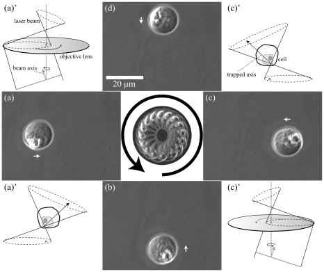 The experiments take advantage of the anisotropy of the trapping field with regard to the laser light path of the front and back of the trapping focus (incoming and outgoing light paths). Since the depth of the trapping potential is proportional to the light intensity, the generated potential also extends along the inherent light axis. This technical problem is practically observed as weakness of the trapping potential along the beam axis compared to that in the vertical plane.11, 12, 13, 14 However, this anisotropic potential matches anisotropic objects, e.g., rods and cells. Thus, the tilt control of the trapping laser is efficiently converted to orientation of the anisotropic object. In a practical setup, there are several techniques for controlling the orientation of a trap laser. One simple technique is identical to the present experiment, in that the tilt of the beam at the conjugated focus (or foci) couples to the orientation of the trap beam, such as in the case of the . A similar effect can be obtained by shifting . A relation between the tilt angle at the focus and variation of the or can be formularized as a function of focal distances of the lenses. However, these controls are actually limited by the objective lens and profile of laser beam. If the beam profile at the back focus is ideally uniform or if it does not have a peak along the beam axis, the orientational force will be rather small. A problem with this tilt-control method is that the tilted beam cannot take full advantage of the NA of the objective; i.e., there is a trade-off between tilt control and trapping efficiency. The essentially new aspect on the presented method is the directional control of a microobject by using a “single tilt-controlled” laser beam. This methodology can avoid difficulty in control of the laser foci inherent to multibeam methods. We believe that the tilt control method decribed in this paper will stimulate future studies applicable for biomedical engineering15 and the construction of microstructures.14 AcknowledgmentsThis work was financially supported by the Sumitomo Foundation, a Grant-in-Aid for Young Scientists (B) from the JSPS, and a Grant-in-Aid for Scientific Research on Priority Areas “System Cell Engineering by Multi-scale Manipulation” from MEXT, Japan. ReferencesA. Ashkin,
“Optical trapping and manipulation of neutral particles using lasers,”
Proc. Natl. Acad. Sci. U.S.A., 94 4853
–4860
(1997). https://doi.org/10.1073/pnas.94.10.4853 0027-8424 Google Scholar
K. Kubo,
M. Ichikawa,
K. Yoshikawa,
Y. Koyama,
T. Niidome,
T. Yamaoka, and
S.-I. M. Nomura,
“Optically driven transport into a living cell,”
Appl. Phys. Lett., 83 2468
–2470
(2003). https://doi.org/10.1063/1.1613356 0003-6951 Google Scholar
H. Misawa,
K. Sasaki,
M. Koshioka,
N. Kitamura, and
H. Masuhara,
“Multibeam laser manipulation and fixation of microparticles,”
Appl. Phys. Lett., 60 310
–312
(1992). https://doi.org/10.1063/1.106695 0003-6951 Google Scholar
H. Kobayashi,
I. Ishimaru,
R. Hyodo,
T. Yasokawa,
K. Ishizaki,
S. Kuriyama,
T. Masaki,
S. Nakai,
K. Takegawa, and
N. Tanaka,
“A precise method for rotating single cells,”
Appl. Phys. Lett., 88 131103
(2006). https://doi.org/10.1063/1.2190268 0003-6951 Google Scholar
M. E. J. Friese,
T. A. Nieminen,
N. R. Heckenberg, and
H. Rubinsztein-Dunlop,
“Optical alignment and spinning of laser-trapped microscopic particles,”
Nature (London), 394 348
–350
(1998). https://doi.org/10.1038/28566 0028-0836 Google Scholar
N. B. Simpson,
K. Dholakia,
L. Allen, and
M. J. Padgett,
“Mechanical equivalence of spin and orbital angular momentum of light: an optical spanner,”
Opt. Lett., 22 52
–54
(1997). https://doi.org/10.1038/022052a0 0146-9592 Google Scholar
E. Higurashi,
H. Ukita,
H. Tanaka, and
O. Ohguchi,
“Optically induced rotation of anisotropic micro-objects fabricated by surface micromachining,”
Appl. Phys. Lett., 64 2209
–2210
(1994). https://doi.org/10.1063/1.111675 0003-6951 Google Scholar
S. L. Mohanty and
P. K. Gupta,
“Laser-assisted three-dimensional rotation of microscopic objects,”
Rev. Sci. Instrum., 75 2320
–2322
(2004). https://doi.org/10.1063/1.1764613 0034-6748 Google Scholar
S. L. Mohanty,
R. Dasgupta, and
P. K. Gupta,
“Three-dimensional orientation of microscopic objects using combined elliptical and point optical tweezers,”
Appl. Phys. B, 81 1063
–1066
(2005). https://doi.org/10.1007/s00340-005-1970-7 0946-2171 Google Scholar
D. G. Grier,
“A revolution in optical manipulation,”
Nature (London), 424 810
–816
(2003). https://doi.org/10.1038/nature01935 0028-0836 Google Scholar
R. C. Gauthier,
M. Ashman, and
C. P. Grover,
“Experimental confirmation of the optical-trapping properties of cylindrical objects,”
Appl. Opt., 38 4861
–4869
(1999). 0003-6935 Google Scholar
V. Garcés-Chávez,
D. McGloin,
H. Melville,
W. Sibbett, and
K. Dholakia,
“Simultaneous micromanipulation in multiple planes using a self-reconstructing light beam,”
Nature (London), 419 145
–147
(2002). https://doi.org/10.1038/nature01007 0028-0836 Google Scholar
M. Ichikawa,
Y. Matsuzawa,
Y. Koyama, and
K. Yoshikawa,
“Molecular fabrication: aligning DNA molecules as building blocks,”
Langmuir, 19 5444
–5447
(2003). https://doi.org/10.1021/la034338t 0743-7463 Google Scholar
P. J. Pauzauskie,
A. Radenovic,
E. Trepagnier,
H. Shroff,
P. Yang, and
J. Liphardt,
“Optical trapping and integration of semiconductor nanowire assemblies in water,”
Nat. Mater., 5 97
–101
(2006). https://doi.org/10.1038/nmat1563 1476-1122 Google Scholar
L. Sacconi,
I. M. Tolić-Norrelykke,
R. Antolini, and
Francesco S. Pavone,
“Combined intracellular three-dimensional imaging and selective nanosurgery by a nonlinear microscope,”
J. Biomed. Opt., 10 14002
(2005). 1083-3668 Google Scholar
|


