|
|
1.IntroductionIn vivo images of the human retina are limited by the presence of both diffraction and aberrations. Diffraction effects are reduced by simple pharmacological dilation of the pupil, but this exacerbates any aberrations present. Wavefront aberrations are then ameliorated by shaping a deformable mirror to produce diffraction-limited image quality. This technology is known as adaptive optics (AO) and has been used for almost a decade to produce images of single cells in live human eyes.1, 2 However, in AO the aberrations are corrected only at the particular point at which the aberrations were measured. For retinal positions away from this point, the wavefront once again becomes distorted and image quality is degraded. In practice, there is a small area centered on the corrected point over which the wavefront aberrations remain relatively constant, and so image quality remains effectively diffraction limited. This is called the isoplanatic patch.3 The criterion selected to define the size of the patch is somewhat arbitrary, and depends on the resolution required for the desired application. One criterion often used is the Maréchal criterion, which states that root mean square (rms) wavefront error of is essentially diffraction limited.4 The technology for AO retinal imaging was originally adapted from astronomy where the size of the isoplanatic patch is rather small: to in the visible range, and still only3 tens of arcseconds in the IR. Recently, efforts have been made to increase the size of this patch. One method proposed is “multiconjugate” AO (MCAO), whereby multiple deformable mirrors are focused to different depths in the aberrating media (the turbulent atmosphere), instead of the conventional single-mirror conjugate to the pupil plane. Wavefront information for these corrections must be collected from multiple point sources within the field of observation. In astronomy, this technology can theoretically improve the diameter of the isoplanatic patch by a factor of 7 to 10 with just three deformable mirrors.5 It is possible to apply MCAO to the human eye to increase the size of the isoplanatic patch beyond6 the limits of conventional AO. However, the value of doing so depends upon the size of the patch obtained via conventional AO—if it is sufficiently large for a particular purpose, then no increase is necessary. Additionally, although the cost of deformable mirrors (and other AO correctors) has decreased recently, price is still a limiting factor if each of the multiple mirrors required must be of the highest quality. In this paper, we aim to explore how worthwhile it would be to build an MCAO system compared to a conventional AO system for retinal imaging. 2.Previous StudiesThere have been few formally published studies concerning the patch size of the human eye. The results that we are aware of also exhibit differences in the criterion for isoplanatism, sampling used, pupil size, inclusion of tilt in the calculations, and other manipulation of the data. For these reasons it is often difficult to compare results. The available data are summarized in Table 1 and discussed in the following. Table 1Studies yielding information on patch size.
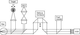
For their first series of images resolving single photoreceptors in human eyes, Liang briefly mentioned that image quality showed no appreciable signs of degradation throughout their 1-deg field of view. From this we can deduce that, for the purpose of imaging cone photoreceptors, the patch size was no less than about . In the works of Maida, 7 Tarrant and Roorda,8 and Dubinin 10, 11 the foveal wavefront is subtracted from wavefronts measured at all eccentricities. Subtracting the foveal wavefront simulates a perfect foveal AO correction when the corrector is conjugate to the pupil. This is the case in conventional AO since corresponding rays from different eccentricities strike the same position on the deformable mirror. In the study of Atchison this subtraction was not performed, and instead the absolute change in rms wavefront error with field position was analyzed. In the Maida 7 study their criterion is not related to the Maréchal criterion, but is instead related to the uncertainty inherent in their wavefront measurements. This is valid since the argument can be made that a zone of significantly different aberration can only be reliably measured when the difference is greater than the error of the machine. However, for the purpose of comparison between researchers a fixed criterion such as the Maréchal is more useful. The Dubinin studies10, 11 use a more relaxed criterion than the Maréchal, being a residual wavefront mean square error of . This corresponds11 to a Strehl ratio of . The Maréchal, on the other hand, corresponds4 to a Strehl ratio of . These studies therefore provide a larger estimate of patch size than studies using the Maréchal. The Atchison study9 and Dubinin 10, 11 studies perhaps paint a limited picture due to only measuring aberrations in one meridian. The Dubinin studies also may overestimate the patch size compared to the others since smaller pupil sizes were used, resulting in aberrations of lower magnitude. The larger pupil size of used by the other studies is more appropriate for AO imaging applications, which aim to minimize diffraction effects. Current ophthalmic AO systems have been able to achieve diffraction-limited imaging only for pupils of diameter or less,12 so considering even larger pupil sizes seems unwarranted. Of course, this may change with the advent of better deformable mirror technology. Additionally, the patch estimate determined in the Atchison study is derived from the change in spherical refractive error (defocus) alone. The actual patch could have been smaller than this since higher order aberrations such as coma change across the field. The Dubinin 10 study incorporates tilt in their RMS calculations. Since tilt by itself does not affect resolution, its inclusion leads to an underestimate of patch size. For this reason, tilt is explicitly discounted in the Dubinin 11 study and subsequently larger estimates of patch size were obtained. As already mentioned, the foveal wavefront should be subtracted from all data points, and the resulting rms wavefront error calculated. When calculating the residual rms following such a subtraction of wavefronts, the effect of noise in each individual aberration contributes a small positive number to the total rms calculated. Thus the rms is said to sit on a “noise floor,” and this should be subtracted when calculating the rms of the difference between wavefronts.13 The 2006 study from Roorda’s group allowed for the noise floor, but it is unclear whether their 2004 study did. We adopted the use of the noise floor concept in this study. 3.MethodsMeasurements were made on the left eyes of seven healthy subjects (six male and one female), aged 22 to 39. All subjects read and signed informed consent documents prior to testing, and all procedures were carried out in accordance with Australia’s National Health and Medical Research Council (NHMRC) guidelines for human observers, which is based on the tenets of the Declaration of Helsinki, and approved by the relevant local Human Research Ethics Committee. Full optometry examinations were conducted on each subject before testing. No significant ocular pathology was present and no subject had spherical refractive error greater than or astigmatic error greater than in magnitude. Subject’s pupils were dilated and accommodation paralyzed using one drop of 1% cyclopentolate hydrochloride prior to aberrometry. The apparatus used is depicted in Fig. 1 . A custom-built Hartmann-Shack device mounted on a standard slit-lamp base was employed to measure aberrations at 49 retinal locations. A fixation target was placed at the far point of the eye using a Badal optometer so that the angular size of the target remained constant. The target, also shown in Fig. 1, comprised a series of six concentric rings. Fixation was directed in 1-deg increments along four meridians spaced apart. It is unlikely that such small shifts in gaze would significantly alter the aberrations by way of mechanical globe deformation.14 Three measurements were taken at each fixation point, each analyzed by fitting a set of 10th-order Zernike polynomials across a pupil diameter of using MatLab (The MathWorks; http://www.mathworks.com). Standard conventions were followed for the ordering of the Zernike polynomials.15 To obtain an estimate of the wavefront over the entire field, a cubic spline was used to interpolate rms wavefront error between measured points and between meridia, in 0.05-deg steps. Note that when performing off-axis aberrometry the pupil appears elliptical in shape. This should ideally be compensated for in the fitting of Zernikes, which apply only over the unit pupil. However, the necessary transformations are negligible for the small eccentricities used here.16, 17 The source was a superluminescent diode (SLD) with peak emittance at and a half-bandwidth of . The SLD is preferable to a laser since SLDs have low coherence, which reduces noise due to laser speckle.12 The reflective/transmittive properties of the beamsplitters used were such that the power of the SLD at the cornea was less than . For the procedure and theory regarding operation of a Hartmann-Shack wavefront sensor, we refer the reader to the literature.12, 18 To determine the isoplanatic patch size, the foveal wavefront was subtracted from each measured wavefront. The residual rms wavefront error was then calculated at each point, ignoring piston and tilt since these have no effect on the resolution of retinal images, before the noise floor was subtracted. In their calculation of the noise floor, Cheng assumed that the standard deviation in the measurement of each Zernike term was a fixed value independent of subject or amplitude of the Zernike term.13 We adopted this approach and extended it so that wavefront errors measured at all eccentricities are assumed to have the same measurement uncertainty. The approach is validated by analysis of our repeated measures; variance does not appear correlated with magnitude of wavefront error, position in the field, or subject. This assumption enables us to pool together around 1000 aberration measurements (data measured at 49 different eccentricities, three measurements per eccentricity for seven subjects) to calculate the noise floor for our system. The isoplanatic patch is defined as the image field area over which some metric of optical quality is considered to be diffraction limited. We explore the patch size for a range of image quality criteria. In this paper, we adopt a slightly stringent stance in demarcation of a circular patch—the closest point to the central corrected point that is above the criterion is considered as the edge of the patch. The distance between this and the central point is then doubled to produce a patch diameter. We adopt this approach instead of taking an average of the patch diameter because (1) the patch size can be oddly shaped or asymmetric, but it is the first departure from the desired image quality that should be used; and (2) correction of some Zernike terms but not others can lead to the patch not being centered on the point of correction (in some cases, not including the point of correction at all). Results are compared with calculations made upon the Liou Brennan schematic eye,19 using optical design software ZEMAX (ZEMAX Development Corporation; www.zemax.com). This eye was chosen since it is an anatomically accurate schematic eye, with representative axial lengths, curvatures, and asphericities, a gradient index lens, a decentered pupil, and an off-axis fovea. To allow this eye to be used away from the fovea, a retinal radius of curvature of was assumed. High-order aberrations of the model eye are expected to be less than seen in real eyes because human eyes are irregular on the microscopic scale due to the tear film, small media opacities, etc. We also explored the relationship between the size of the patch and particular aberrations corrected. This information is of use to determine the quality of deformable mirror that should be employed to achieve a desired isoplanatic patch size following AO correction. Therefore, we systematically and cumulatively modeled AO correction of particular Zernike terms and computed the resulting patch size. This is achieved by subtracting the applicable foveal Zernike terms from all data points and calculating the resulting rms. This does not specifically yield information about which aberrations change the most with eccentricity, since patch size depends both on this and on the residual aberrations at the central point. This information is important in determining which Zernike terms should be targeted for a MCAO correction. We therefore considered an idealized case where a perfect correction for the central beacon has been achieved—i.e., all foveal aberrations subtracted from all points. On top of this, we set to zero particular Zernike terms for all the peripheral points and computed the resulting patch size. This procedure is analogous to MCAO correction, although it produces unrealistic patch sizes since a very large number of mirrors and source beacons would be required, compared to only five beacons and two to three mirrors likely to be used in practice.6 However, it provides us with information on which aberrations change the most with eccentricity, and so which are most important to compensate in a MCAO system. 4.ResultsFor the reader to appreciate baseline wavefront error magnitudes, we note the following characteristics of our data assuming full correction of foveal spherocylindrical effects and a 6.0-mm pupil: average foveal rms was (0.08 to ); rms averaged over the 12-deg diameter circular field was (0.17 to ); rms for the best point in the 12-deg field was (0.08 to ); rms for the worst point in the 12-deg field was (0.34 to ). Although not a good predictor for the mean, the performance of the model was similar to the best-performing eye in our study: foveal rms was , mean rms was , best rms was , and worst RMS was over a 12-deg diameter field. Figure 2 shows the isoplanatic patch sizes obtained for all subjects using the Maréchal criterion for 555-nm light. Although we will be using the more stringent criterion as discussed above (i.e., the patch size in the worst direction determines the patch diameter), we included for comparison with other work the patch size obtained if the average is taken of all eight directions. Our average values are slightly less than other estimates from the literature. It is also clear that the isoplanatic patch of the model eye is far larger than that of our subjects. This is attributable to significant levels of aberrations above fourth order that are not included in the eye model, as becomes apparent in the following. Fig. 2Isoplanatic patch diameter for the model eye and the mean for Seven subjects (A to G), defined by the Maréchal criterion for 555-nm light. Subject “Z” shows data from the model eye obtained with Zemax, and is not included in the “mean” calculation. Darker bars show minimum diameter of the patch, and lighter bars show average diameter. Error bars are standard deviation. 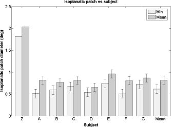 Of the available published (and unpublished) retinal images,1, 12 the actual noticeable region of stable image quality in the eye is usually 1 to , which does not correlate well to our data using the Maréchal criterion for 555-nm light. Perhaps in the future some criterion will be chosen that correlates more closely to discerning particular retinal microstructure. Figure 3 shows patch size plotted as a function of the criterion chosen, depicting the model eye and the mean of all subjects. The data were quite linear. Regression gave a mean slope of , . The first data point corresponds to the Maréchal criterion at , and subsequent data points correspond to Maréchal criteria in 50-nm steps. The size of the patch is larger as expected with longer imaging wavelengths, due to higher Maréchal criteria for those wavelengths. Of course, image quality will be balanced somewhat by worse diffractive effects at longer wavelengths. A criterion of rms corresponds well with realistic levels of residual aberration reported12 for many modern AO systems after conventional AO. For this reason, we selected this criterion over the Maréchal in several examples below. Above rms, the data were not well behaved due to fragmentation of the patch. Fig. 3Circular isoplanatic patch diameter versus criterion. Data for each subject were linear, with . Mean slope was . The flat nature of the data compared with the model indicates that the subjects have worse off-axis image quality than the model. Error bars are standard deviation.  Figure 4 shows relative isoplanatic patch diameter versus particular Zernike terms corrected in conventional AO. Note that the plot is cumulative, such that each specified group of Zernike terms includes all the ones before it. For this patch criterion of rms, the performance of five of the subjects seemed to plateau after correction to just sixth order, however, the remaining two subjects showed little plateau effect. The model eye is corrected to 99% with the correction of spherical aberration together with third-order and lower terms. Note that some model eye and individual subject data points were actually slightly lower than preceding data points—this is due to the point of best rms not necessarily being coincident with the point of correction (the fovea). For example, incorporating a coma correction in the model eye causes the area of isoplanatism to widen, but also shifts it slightly from the fovea (since the point of zero coma is not precisely at the fovea in the first place). It can be seen that correction of defocus alone did not allow the patch criterion to be met, even at the fovea, in any subject or in the model eye. Patch size was therefore zero each time for this case. Fig. 4Proportion of maximum possible patch diameter achieved as a function of which aberrations are corrected at the fovea. Correction of each aberration category includes correction of all the categories to its left. The criterion for patch diameter here is rms. The mean does not include the model eye. Error bars are standard deviation. The dashed horizontal line indicates where 80% of the possible patch diameter has been achieved. 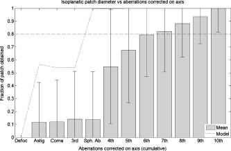 We next repeated the preceding analysis for a range of patch criteria, and determined the order of Zernike terms required to achieve an arbitrary fraction of the possible patch diameter in each case. This fraction was chosen to be 80%, as shown by the dotted line in Fig. 4 for a criterion of rms. Figure 5 plots the Zernike terms required to achieve this fraction of the patch as a function of patch criterion. Individual symbols show data for each subject. Fig. 5Aberrations that must be corrected at the fovea to achieve 80% of the possible patch size versus criterion for the patch size. Correction of each aberration category includes correction of the categories below it. Nonlegend symbols indicate data for individual subjects. The mean does not include the model eye.  We can see that to obtain a decent fraction of the best available patch for the more stringent criteria (i.e., Maréchal at ; rms ), correction of aberrations up to 10th order would be desirable. Since the data reaches this limit, it would be interesting to know whether Zernike fits of even higher orders would be beneficial in representing the wavefront. Fits of up to tenth order are mentioned routinely in vision science, but rarely higher. For the more realistically achievable criteria the requirement for correction was lower in most subjects. For a residual rms of and Zernike correction to seventh order, 80% of the maximum possible patch was achieved in five of seven subjects. However, the other two subjects did not show as much of a plateau effect with the incorporation of more Zernike orders—correction of up to ninth order was still required. Figure 6 shows the isoplanatic patch obtained when particular off-axis aberrations are corrected by simulating an idealized multi-conjugate system. The criterion for the patch was rms, and corrections shown are again cumulative. A patch diameter of is the highest that we could measure given the range of our data, and so patches that would probably have been larger are recorded as in size. We can see that worthwhile gains are made in patch size with correction at least to sixth to eighth order. For more stringent patch criteria, correction of even higher orders would be desired. A misleading feature of this plot is that correction of the lower order terms does not appear to improve patch size very much compared to the higher order terms. This is a product of the fact that even when the lower order terms are corrected, the patch size is still limited by the presence of the higher order terms. Fig. 6Isoplanatic patch diameter versus which aberrations are correction in an idealized MCAO system. A perfect foveal correction is combined with correction of only specific aberrations at each off-axis point. Each aberration correction category includes correction of all the categories to its left. The criterion for the patch was rms wavefront error. Error bars are standard deviation. 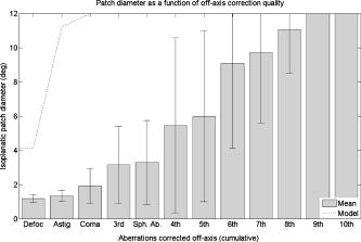 For this reason, Fig. 6 does not reveal which aberrations in particular are most important in off-axis image degradation. Figure 7 considers each of the preceding Zernike categories individually to explore this, using the same criterion of rms. Note that the plot in Fig. 7 now shows which particular groups of Zernike terms are present—i.e., all other Zernike terms are corrected. The vertical axis is the inverse of the patch size and hence is a direct measure of how important a particular set of aberrations are. We can see that the most important change with eccentricity occurred for astigmatism in the model eye, and astigmatism, coma, and defocus in the real eyes. The seeming dependence of the model eye solely on astigmatism is an artifact of the lax rms criterion—for this case, astigmatism was the only aberration that changed markedly enough away from the fovea to cause a decrease in patch size if left uncorrected. Although not depicted here, for more strict criteria, defocus and coma had significant influence on the model eye as expected. Fig. 7Aberrations that change most significantly away from the fovea. A perfect foveal correction is combined with correction of all peripheral aberrations except the specified Zernike terms. Each category is considered individually-categories to the left are not included (e.g., “Other 3rd,” denotes third-order aberrations other than coma). Note that no patch was achieved in three of the subjects with defocus left uncorrected. The criterion for the patch was rms wavefront error. Error bars are standard deviation.  5.DiscussionThe mean patch size obtained using the Maréchal criterion for 555-nm light was . For a more lax stance in which the average of all eight directions is used, mean diameter was . This is somewhat smaller than other estimates of the isoplanatic patch already discussed (which tend to range between 1 and ), but factors such as smaller pupil size, different patch criteria, and differences in data manipulation may explain these discrepancies. The Liou-Brennan eye model showed a significantly larger patch size because it does not predict significant levels of aberration above fourth order, and subsequent changes in those aberrations across the field, as are found in real eyes. Such aberrations are likely the result of subtle irregularities found in real ocular tissue combined with optical components that are slightly decentred and tilted with respect to each other. An interesting consideration in making use of the isoplanatic patch for AO retinal imaging is how wide we can make our field of view before camera resolution decreases to the point where we can no longer take advantage of improved image quality. If the field size at this limit is similar to the isoplanatic patch size, then it is not worth improving on conventional AO imaging. On the other hand, if the limit is considerably larger than the conventional AO isoplanatic patch, it is worthwhile to increase the size of the patch through MCAO. In the case of conventional flood-based illumination of the retina, the field-limiting factor is the size and resolution of the CCD camera. Current CCD cameras with sufficient speed and sensitivity for retinal imaging are (2000 pixels along a side). Using the Rayleigh criterion for resolution of two points coupled with the Nyquist sampling theorem, pixels on our detector must be spaced twice as close together as the half width of the PSF. According to Zemax, the model eye at the Maréchal limit has a PSF half width of . Therefore pixels must be spaced apart. Assuming a square 4-Mpixel array, we have 2000 pixels spaced apart, which is across. Compared to the isoplanatic patch of the eye, there is significant potential for improvement through MCAO. Due to residual aberrations, however, real AO systems rarely achieve the diffraction limit. It may be more realistic then to raise our criterion for the patch somewhat, which will increase the patch size—but it will also increase the field achievable by the camera, since individual pixels need not correspond to such small areas of retina in the presence of slight blurring. The relative benefit of MCAO should therefore still apply. These considerations on camera resolution do not apply to other imaging techniques such as scanning laser ophthalmoscopy (SLO) or optical coherence tomography (OCT). In the case of SLO and in many implementations of OCT, raster scans are made across the retina quickly so that only a small region is imaged at one moment in time. The limiting factors for these techniques to be able to take advantage of MCAO in real time are therefore photon noise and the rate at which raster scans can be reliably digitized. Selecting a sensible criterion that enables resolution of desired retinal features remains unexplored. However, our results show that patch size increases proportionally with the criterion chosen. For the more realistically obtained residual rms of , mean patch size was . Based on idealized simulated corrections for AO and MCAO, correctors capable of replicating aberrations up to the 10th order would be beneficial to achieve diffraction-limited imaging in a large proportion of subjects. In terms of a lower cost conventional AO system with more relaxed patch criteria, aberration correction to sixth to eighth order is expected to cater for the majority of subjects. For multiconjugate corrections, mirrors that have good capacity to correct for defocus, astigmatism, and coma are most desirable. ReferencesJ. Liang,
D. R. Williams, and
D. T. Miller,
“Supernormal vision and high-resolution retinal imaging through adaptive optics,”
J. Opt. Soc. Am. A, 14 2884
–2892
(1997). 0740-3232 Google Scholar
D. C. Gray,
W. Merigan,
J. I. Wolfing,
B. P. Gee,
J. Porter,
A. Dubra,
T. H. Twietmeyer,
K. Ahamd,
R. Tumbar,
F. Reinholtz, and
D. R. Williams,
“In vivo fluorescence imaging of primate retinal ganglion cells and retinal pigment epithelial cells,”
Opt. Express, 14 7144
–7158
(2006). https://doi.org/10.1364/OE.14.007144 1094-4087 Google Scholar
D. L. Fried,
“Anisoplanatism in adaptive optics,”
J. Opt. Soc. Am., 72 52
–61
(1982). 0030-3941 Google Scholar
M. Born and
E. Wolf, Principles of Optics, 5th ed.Pergamon Press, Oxford (1975). Google Scholar
A. Tokovinin,
M. Le Louarn, and
M. Sarazin,
“Isoplanatism in a multiconjugate adaptive optics system,”
J. Opt. Soc. Am. A, 17 1819
–1827
(2000). 0740-3232 Google Scholar
P. A. Bedggood,
R. Ashman,
G. Smith, and
A. B. Metha,
“Multiconjugate adaptive optics applied to an anatomically accurate human eye model,”
Opt. Express, 14 8019
–8030
(2006). https://doi.org/10.1364/OE.14.008019 1094-4087 Google Scholar
E. M. Maida,
K. Venkateswaran,
J. Marsack, and
A. Roorda,
“What is the size of the isoplanatic patch in the human eye?,”
(2004) http://wwwcfao.ucolick.org/EO/internshipsnew/mainland/posters/erika.pdf Google Scholar
J. Tarrant and
A. Roorda,
“The Extent of the Isoplanatic Patch of the Human Eye,”
(2006) http://vision.berkeley.edu/wildsoet/Arvo2006/Isoplanatic%20Patch_Janice_Austin.pdf Google Scholar
D. A. Atchison,
S. D. Lucas,
R. Ashman,
M. A. Huynh,
D. W. Schilt, and
P. Q. Ngo,
“Refraction and aberration across the horizontal central 10 degrees of the visual field,”
Optom. Vision Sci., 83 213
–221
(2006). https://doi.org/10.1097/01.opx.0000214382.75847.c4 1040-5488 Google Scholar
A. Dubinin,
T. Cherezova,
A. Belyakov, and
A. Kudryashov,
“Anisoplanatism in human retina imaging,”
Proc. SPIE, 5894 88
–94
(2005). 0277-786X Google Scholar
A. Dubinin,
T. Cherezova,
A. Belyakov, and
A. Kudryashov,
“Human eye anisoplanatism: eye as a lamellar structure,”
Proc. SPIE, 6138 613813
(2006). 0277-786X Google Scholar
J. Porter,
J. E. Lin, and
H. Queener, Adaptive Optics for Vision Science, Wiley-Interscience, New York
(2006). Google Scholar
H. Cheng,
J. K. Barnett,
A. S. Vilupuru,
J. D. Marsack,
S. Kasthurirangan,
R. A. Applegate, and
A. Roorda,
“A population study on changes in wave aberrations with accommodation,”
J. Vision, 4 272
–280
(2004). 1534-7362 Google Scholar
R. Ashman,
M. Daaboul,
D. A. Atchison,
G. Smith, and
A. Metha,
“Effects of torsion on ocular aberrations,”
Google Scholar
L. N. Thibos,
R. A. Applegate,
J. T. Schwiegerling, and
R. Webb,
“Standards for reporting the optical aberrations of eyes,”
J. Refract. Surg., 18 S652
–S660
(2002). 1081-597X Google Scholar
D. A. Atchison,
D. H. Scott, and
W. N. Charman,
“Measuring ocular aberrations in the peripheral visual field using Hartmann-Shack aberrometry,”
J. Opt. Soc. Am. A Opt. Image Sci. Vis, 24 2963
–2973
(2007). 1084-7529 Google Scholar
L. Lundstrom and
P. Unsbo,
“Transformation of Zernike coefficients: scaled, translated, and rotated wavefronts with circular and elliptical pupils,”
J. Opt. Soc. Am. A Opt. Image Sci. Vis, 24 569
–577
(2007). 1084-7529 Google Scholar
J. Liang,
B. Grimm,
S. Goelz, and
J. F. Bille,
“Objective measurement of wave aberrations of the human eye with the use of a Hartmann-Shackwave-front sensor,”
J. Opt. Soc. Am. A Opt. Image Sci. Vis, 11 1949
–1957
(1994). 1084-7529 Google Scholar
H.-L. Liou and
N. A. Brennan,
“Anatomically accurate, finite model eye for optical modeling,”
J. Opt. Soc. Am. A, 14 1684
–1694
(1997). 0740-3232 Google Scholar
|