|
|
1.IntroductionImaging using optical methods is of primary importance in further understanding biological systems.1 Coherence-gated imaging techniques, such as optical coherence tomography (OCT)2 or coherence-gated photorefractive holography,3 enable the imaging of a point (OCT) or plane (holography) within a three-dimensional volume of a biological material with a spatial resolution on the order of a few microns. In addition to imaging, in order to obtain a more complete biomechanical characterization of soft tissue, strain information relative to the images must be simultaneously measured. Recently, we demonstrated the direct simultaneous acquisition of both coherent imaging and strain information by coupling photorefractive holography with shearography.4 Here, we demonstrate that the imaging and strain information yielded by this coupled system can be obtained through a synthetic medium (tissue phantoms composed of silica spheres suspended in water1) that approximates the optical scattering properties of biological soft tissue. 2.Scattering PhantomsRayleigh scattering is used to describe scattering by particles that are smaller than the illumination wavelength, whereas Mie scattering is used to describe scattering with particles that are larger than the illumination wavelength.5 Though Mie scattering is the predominant scattering regime in biological media,1 both Rayleigh and Mie scattering regimes must be considered for a thorough study of soft tissue because of the wide range in the size of biological structures. In addition, scatterers often do not have spherical shape; furthermore, multiple scattering can occur because of the high density of scatterers. Multiple scattering occurs when the distance between two scattering entities is smaller than approximately four times their radii.6 In our experiments, we constructed synthetic scattering phantoms from monodisperse suspensions of spherical silica particles (beads) in water. Solutions of beads were prepared at the Institut de Physique et Chimie des Matériaux de Strasbourg (IPCMS) using the Stöber reaction.7, 8 As reported in the literature,9 the scattering properties of biological tissue can be modeled by a mix of spherical particles with continuous-size dispersion. Three separate solution types were used, with spheres of 250, 400, and in diameter (size dispersion of ca. 5%), respectively, at various concentrations. The scattering cell thickness along the light beam axis was . The bead concentrations in each tissue phantom were chosen to correspond to a range of physiologically relevant optical densities. For spheres with a diameter of , Rayleigh scattering occurs; for spheres with a diameter of , the scattering is mixed (both Rayleigh and Mie); and for spheres with a diameter of , Mie scattering dominates. In the Rayleigh scattering regime, light is scattered in all directions and its intensity varies as . In the Mie scattering regime, light is mainly scattered in the forward direction and the intensity dependence upon is more complex, as described by rigorous Lorenz–Mie theory.6, 10 At a wavelength of , the sphere refractive index is 1.495 and the surrounding water refractive index is 1.36. When an incident beam of flux passes through a cell of thickness with a concentration, , of scattering entities for which the extinction crosssection is , the transmitted intensity, , follows the Beer–Lambert law: Assuming that simple scattering is the dominant extinction mechanism in the synthetic phantoms and that absorption can therefore be neglected, can be calculated with Lorenz–Mie theory.11 In order to experimentally verify that the sphere concentrations and diameters corresponded to the experimental requirements (Table 1 ), we measured the optical density of the synthetic phantoms for the different bead sizes as a function of wavelength using a white light source and a spectrometer. The optical density is given by Table 1Microspheres concentrations, τ , used in a cell of thickness 2×5mm (double passage), tilted at a 10° angle, over a range of optical densities at λ=532nm . Concentrations are given in units of 1010spheres∕l .
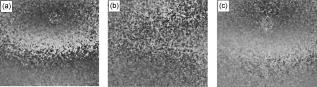
The measured optical density data and corresponding fits to the Beer–Lambert law are shown as a function of wavelength in Fig. 1 . The goodness of fit to the model confirms both that the bead suspensions were correctly prepared and that the Beer–Lambert model applies. Fig. 1Absorption spectra of the various bead suspensions (beads of , , and in diameter) at various concentrations in a cell and the corresponding fits to the Beer–Lambert law [Eq. 1]. 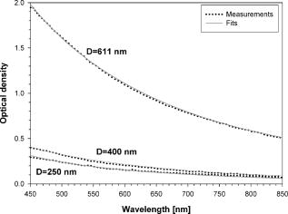 3.Shearography Through Scattering Media3.1.MethodsDigital shearography,12 or digital speckle shearing interferometry, is a full-field, noncontact coherent optical technique used to measure directly the displacement gradient (deformation/strain) across a surface by using a digital camera as the recording device. The key element in a shearing interferometry system is the shearing device, which causes the light scattered from two neighboring regions on a test surface to interfere at a point in the image plane of the camera. The shearographic interferometer used in this work13 is shown in Fig. 2 . A frequency-doubled Nd:YAG laser ( , ) polarized at with respect to the plane of the optical table was used as the light source. A speckle pattern is produced by reflection of the incident light from the test object’s surface. In order to produce well-developed speckle patterns in our experiments, a steel plate was used as a test object. The interferograms (shearograms) recorded by the CCD camera result from the interference between the object speckle wavefront and the same speckle wavefront shifted laterally along the direction by the shearing element13 (shearing distance of in the experiments). For every state of the test object (unloaded reference state and loaded states) in the experiments, a set of four shearograms, phase-shifted relative to each other, was recorded by varying the control voltage of the phase modulator [liquid crystal variable retarder (LCVR)]. Wrapped phase difference maps sensitive to the -component of the out-of-plane displacement gradient were obtained with a standard four-step algorithm13 applied separately to the two sets of phase-shifted shearograms acquired before and after loading, followed by phase map subtraction. Fig. 2Experimental setup for shearography. The black square corresponds to the imaged area on the steel plate. 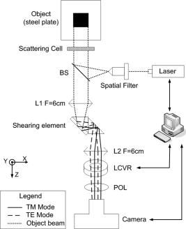 In order to produce exactly the same load at the same point of the test object for each experiment, the plate was held horizontally by three steel posts screwed into the optical bench. A small hole was pierced at the center of mass of the isosceles triangle formed by the three posts in order to hold, in a reproducible way, a ball of known mass . The scattering phantom was located in front of the test surface. 3.2.Results and DiscussionA area of the steel plate roughly centered on the loading point was imaged by the shearographic interferometer. A qualitative evaluation of the influence of the scattering medium on the interferometer is given in Fig. 3 , which shows three wrapped phase maps obtained without the scattering cell as well as with the cell at two different concentrations of beads. All other experimental parameters were kept constant during the different experiments—only the CCD exposure time was increased to maintain a constant mean irradiance in the recorded shearograms. One fringe in the phase maps corresponds to a strain (displacement gradient) magnitude of in the shearing direction . In observing the different phase maps in Fig. 3, it is apparent that a deterioration of the contrast occurs with increasing optical density. Fig. 3Wrapped differential phase maps ( median filtered) obtained with the shearography setup. (a) Without a scattering cell; (b) with a scattering cell: ; (c) with a scattering cell: . 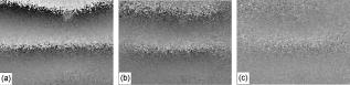 A quantitative analysis of the phase map degradation as a function of optical density was undertaken using the contrast,14 , of the fringes, defined as follows: where and are median intensity values determined at the fringe maxima and minima, respectively. The fringes have a sawtooth profile and the discontinuities appear as jumps from white pixels (phase difference of radians) to black pixels (phase difference of zero radians). The exact position of the phase jumps is blurred by the inherently noisy nature of the speckle interferograms. Therefore, a kernel was used to calculate the median value at the peak of white intensity levels of the sawtooth function to determine , and the same process was used to determine . The different steps leading to the determination of and are summarized in Fig. 4 .Shearographic fringe contrast versus optical density for silica sphere scattering phantoms is shown in Fig. 5 for various concentrations. The figure shows that the fringe contrast decreases with increasing optical density of the scattering cells, as expected from the images in Fig. 3. The decrease in fringe contrast is attributable to progressively greater loss of spatial coherence due to the Brownian motion of the particles in the scattering cells. It has long been known that speckle noise can be reduced in holographic images by placing a moving diffuser in the light path.15 Since spatial coherence is critical in shearography, the effect of deteriorating spatial coherence is clearly seen in the experimental results. Fig. 5Contrast of the shearographic fringes versus optical density for different scattering phantoms composed of silica spheres in suspension in distilled water. 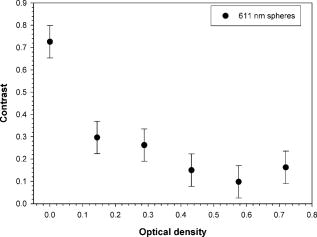 Note that from Rayleigh and Mie theory, it is expected that experiments with bead diameters of and should yield similar results and tendencies but with slightly different numerical values. Because of the unavoidable fairly large uncertainty (10%) in determining the speckle fringe contrast, the expected small numerical differences in the data obtained with and beads could not be observed experimentally. We chose therefore to conduct the remainder of our contrast measurement experiments with beads only. 4.Photorefractive Holography Through Scattering Media4.1.MethodsCoherence-gated photorefractive holography3 is a full-field, noncontact coherent optical technique similar, in some respects, to OCT2 (both make use of a short-coherence light source). However, photorefractive holography has two advantages over OCT: First, optical coherence tomography is generally a pointwise scanning technique, whereas photorefractive holography is full-field (an entire plane is imaged in a single acquisition). Second, since the photorefractive effect is only sensitive to the gradient of optical illumination, incoherent light (i.e., nonballistic photons) that is not involved in interference does not contribute to the photorefractive effect.16 Hence, the photorefractive medium naturally filters out background-scattered light that would otherwise decrease the signal-to-noise ratio. The experimental setup for photorefractive holography is shown in Fig. 6 . Holograms are recorded in a strontium-barium-niobate (SBN) photorefractive crystal using a TM-polarized frequency-doubled Nd:YAG laser . A beamsplitter (BS) separates the incident beam into two equal-intensity paths: the reflected “object” (signal) beam and the transmitted “reference” (pump) beam. Both beams interfere in the photorefractive crystal, which is positioned so that its crystal lattice orientation is appropriate for the photorefractive effect using TM-polarized light. Once a hologram is recorded in the crystal, the signal beam is switched off using a digitally controlled shutter and the hologram can then read out of the interferometer by the pump beam. Note that for the experiments presented here, a long coherence-length laser source was used in order to simplify the optical alignment. The optical sectioning properties of coherence-gated photorefractive holography afforded by a short coherence-length source were not required since the test object’s surface was opaque. To study the influence of a scattering medium located in front of the test object, holograms were recorded through the tissue phantoms discussed in Section 2. 4.2.Results and DiscussionAs with the shearographic interferometer, qualitative and quantitative evaluations of the influence of the scattering medium on the interferometer were carried out. Again, all the experimental parameters were kept constant in order to permit a comparison of the different recorded holograms. The hologram write time in the photorefractive crystal was kept constant at . Pictures of holograms of the letter “S” (the Université de Sherbrooke logo etched in chromium on a glass substrate) are shown in Fig. 7 , obtained both without (a) and with [(b) and (c)] the scattering cell containing spheres at increasing concentrations. As opposed to shearography, insertion of the scattering cell in front of the object improved the image quality, as expected.15 Indeed, as the concentration of silica sphere diffusers increases, the hologram image quality is enhanced and noise is reduced due to a loss of spatial coherence and a corresponding decrease in speckle amplitude. Fig. 7Holograms obtained with the photorefractive holography setup (a) Without a scattering cell; (b) with a scattering cell: ; (c) with a scattering cell: . 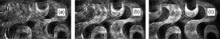 As in Section 3.2, the contrast, , between abrupt dark-to-light transitions in the images [Eq. 3] was used to evaluate quantitatively the quality of the recorded holograms. Figure 8 confirms that the contrast in the holograms improves with increasing optical density of the scattering cell. This improvement in image contrast occurs (1) because of the decrease in laser speckle due to the loss of spatial coherence and (2) because coherent imaging through a liquid scattering medium produces a time-varying diffuse scattered background that averages to a uniform field17 and so is readily rejected by photorefractive effect. 5.Coupled Photorefractive Holography and Shearography Through Scattering Media5.1.MethodsThe coupled setup,4 consisting of the photorefractive holography interferometer (top) followed by the shearographic interferometer (bottom), is shown in Fig. 9 . When the sample under study has an optically rough surface, the light field emerging from the holographic interferometer will be a speckle pattern. Therefore, this “holographic speckle field” can be used for speckle interferometry by the second stage, the digital speckle shearing interferometer. Note that the light emerging from the holographic interferometer is TM-polarized. A half-wave plate is therefore required between the holographic and shearing interferometers in order to rotate the polarization by and thus inject equal amounts of TE- and TM-polarized light into the shearing interferometer. Fig. 9Schematic of the coupled experimental setup: photorefractive holography at the top and digital shearography at the bottom. 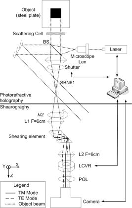 A first hologram of the object in a reference state is recorded, requiring to write the hologram into the SBN crystal. Next, the signal-beam shutter is switched off and the four shearograms required by the phase-shifting algorithm are recorded by the CCD. The acquisition of the four shearograms required in total, which is faster than the hologram erasure time. Under constant illumination by the probe beam, the hologram is completely erased in approximately one minute. Subsequently, the steel plate is centrally loaded and a second hologram is recorded in the SBN crystal, followed by the acquisition of the second set of four phase-shifted shearograms. Finally, the wrapped differential phase maps shown in Fig. 10 were obtained with the four-step algorithm and phase map subtraction. 5.2.Results and DiscussionHere again, a qualitative and quantitative evaluation of the influence of the scattering medium on the coupled system was carried out. All the experimental parameters were kept constant during the different experiments. Three differential phase maps were determined from the sheared holograms without the scattering cell [Fig. 10a] and with the cell containing spheres [Figs. 10b and 10c]. It can be seen by comparing Figs. 10a and 10b that, under the same experimental conditions, the phase map obtained through the scattering medium is degraded compared with that obtained without the scattering cell. Figs. 10b and 10c show the phase maps determined from the sheared holograms obtained with the same scattering cell but with different recording times for the holograms ( and , respectively). By comparing these figures it is apparent that the fringe contrast increases with the recording time. The contrast C [Eq. 3] shown in Fig. 11 confirms this behavior: the more diffusing the medium, the lower the contrast. On the other hand, the greater the recording time, the higher the contrast. Fig. 11Shearographic fringe contrast recorded with the coupled system versus optical density for different scattering phantoms composed of silica spheres in suspension in distilled water, as well as different hologram write times. Increased hologram write times can be seen to restore fringe contrast by restoring the spatial coherence of the input light to the shearographic interferometer.  This important result is attributable to the fact that, though the presence of the scattering cell reduces the spatial coherence of the light at “relatively fast” photorefractive crystal hologram recording times , thereby drastically reducing the quality of the shearograms, longer hologram recording times will restore spatial coherence because ballistic photons will eventually dominate over scattered light due to the properties of the photorefractive effect (sensitivity to the gradient of illumination only, time-averaged integration). 6.ConclusionsWe presented results showing the influence of a scattering medium on data obtained from three interferometers: (1) strain measurements from a shearographic interferometer in isolation; (2) coherent imaging information from a photorefractive holography interferometer in isolation; (3) strain measurements from a coupled shearography and holography system. It was shown that the insertion of a scattering cell in the shearographic interferometer reduces the contrast of the differential phase maps carrying strain information because Brownian motion of the scattering particles decreases the spatial coherence of the input light. In contrast, though the insertion of a scattering cell in the photorefractive holography interferometer also reduces spatial coherence, the effect on image quality is the reverse since reduced speckle amplitude improves the quality of the holograms. Finally, we showed that though the insertion of a scattering cell in the coupled shearography and holography system reduces the shearing fringe contrast, as with the speckle shearing interferometer alone, increasing the hologram write time in the crystal restores the fringe contrast. This effect is due to the fact that the photorefractive medium acts both as a spatial high-pass filter (preferential recording of high spatial frequency information such as speckle) and as a temporal low-pass filter (time integration of weakly scattered ballistic photons and filtering of the dynamically scattered light). This result is of interest for the mechanical characterization of semitransparent optically scattering material such as biological tissue. Indeed, by using a short coherence-length light source, the coupled system will be able to measure strain fields along a plane inside the material volume. In addition, if the imaging path does not cross any major blood vessels, the scattering effects of the tissue are likely to be reduced because the scattering centers will be quasi-static, thereby increasing the contrast of the shearography fringes and the SNR of the strain measurements. AcknowledgmentsThis work was supported by grants from the Natural Sciences and Engineering Research Council of Canada (NSERC), the IV Commission Mixte Permanente Québec-Wallonie/Bruxelles, and the Ministère de la Région Wallonne–Direction des Relations Internationales, Belgium, Biennum 2005–2007. The authors would like to thank Nicolas Stenger and Jean-Luc Rehspringer from the IPCMS Laboratory in Strasbourg for providing the silica spheres. The authors also thank Etienne Grondin from the Université de Sherbrooke for his technical help, Matthieu Martin from the Université de Sherbrooke, and Gary J. Long from the University of Missouri–Rolla for editorial help. ReferencesV. Tuchin, Tissue Optics: Light Scattering Methods and Instruments for Medical Diagnosis, 2nd ed.SPIE Press, Bellingham, WA (2007). Google Scholar
D. Huang,
E. A. Swanson,
C. P. Lin,
J. S. Schuman,
W. G. Stinson,
W. Chang,
M. R. Hee,
T. Flotte,
K. Gregory,
C. A. Puliafto, and
J. G. Fujimoto,
“Optical coherence tomography,”
Science, 254
(5035), 1178
–1181
(1991). https://doi.org/10.1126/science.1957169 0036-8075 Google Scholar
S. C. W. Hyde,
N. P. Barry,
R. Jones,
J. C. Dainty,
P. M. W. French,
M. B. Klein, and
B. A. Wechsler,
“Depth-resolved holographic imaging through scattering media by photorefraction,”
Opt. Lett., 20
(11), 1331
–1333
(1995). 0146-9592 Google Scholar
V. Rosso,
R. Béland,
Y. Renotte,
S. Habraken,
Y. Lion, and
P. Charette,
“Simultaneous coherent imaging and strain measurements using coupled photorefractive holography and shearography,”
Opt. Lett., 33
(8), 797
–799
(2007). https://doi.org/10.1364/OL.33.000797 0146-9592 Google Scholar
W. F. Cheong,
S. A. Prahl, and
A. J. Welch,
“A review of the optical properties of biological tissues,”
IEEE J. Quantum Electron., 26
(12), 2166
–2184
(1990). https://doi.org/10.1109/3.64354 0018-9197 Google Scholar
H. C. Van de Hulst, Light Scattering by Small Particles,
(1981) Google Scholar
W. Stöber,
A. Fink, and
E. Bohn,
“Controlled growth of monodisperse silica spheres in the micron size range,”
J. Colloid Interface Sci., 26 62
–69
(1968). https://doi.org/10.1016/0021-9797(68)90272-5 0021-9797 Google Scholar
R. R. Mafouana,
“Elaboration des matériaux à bande interdite photonique,”
Louis Pasteur University,
(2006). Google Scholar
J. M. Schmitt and
G. Kumar,
“Optical scattering properties of soft tissue a discrete particle model,”
Appl. Opt., 37
(13), 2789
–2797
(1998). 0003-6935 Google Scholar
G. Mie,
“Beiträge zur Optik trüber Medien, speziell kolloidaler Metallösungen,”
Ann. Phys., 25
(4), 377
–445
(1908). https://doi.org/10.1002/andp.19083300302 0003-3804 Google Scholar
S. Lecler,
“Light scattering by sub-micrometric particles,”
(2005) http://www-scd-ulp.u-strasbg.fr/theses/theselec.html Google Scholar
W. Steinchen and
L. Yang, Digital Shearography, SPIE Press, Bellingham, WA (2003). Google Scholar
V. Rosso,
Y. Renotte,
S. Habraken,
Y. Lion,
F. Michel,
V. Moreau, and
B. Tilkens,
“An almost-common path interferometer using the separation of polarization states for digital phase-shifting shearography,”
Opt. Eng., 46
(10), 105601
(2007). https://doi.org/10.1117/1.2795632 0091-3286 Google Scholar
E. Hecht, Optics, 4th ed.Addison-Wesley, San Francisco (2002). Google Scholar
S. Lowenthal and
D. Joyeux,
“Speckle removal by a slowly moving diffuser associated with a motionless diffuser,”
J. Opt. Soc. Am., 61
(7), 847
–850
(1971). 0030-3941 Google Scholar
D. Pepper,
J. Feinberg, and
N. Kukhtarev,
“The photorefractive effect,”
Sci. Am., 263
(4), 34
–40
(1990). 0036-8733 Google Scholar
M. Tziraki,
R. Jones,
P. M. W. French,
M. R. Melloch, and
D. D. Nolte,
“Photorefractive holography for imaging through turbid media using low coherence light,”
Appl. Phys. B: Lasers Opt., 70 151
–154
(2000). https://doi.org/10.1007/s003400050023 0946-2171 Google Scholar
|
|||||||||||||||||||||||||||||||||||||||||||||||||||||