|
|
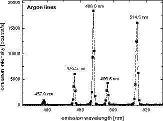
1.IntroductionThe marriage of two well-known scientific methodologies—namely, (fluorescence) spectroscopy and imaging—gave birth to a novel imaging method known as spectral imaging. One major advantage of spectral imaging is the capability to unmix cross-talk and discriminate distinct fluorophores with highly overlapping fluorescence emissions.1, 2, 3, 4 It also provides a unique capability for detecting spectral changes in fluorescent indicators, for instance, in indicators that employ fluorescence resonance energy transfer (FRET).5, 6, 7 In biological imaging, spectral imaging has been first implemented in a widefield fluorescence microscope using a single stationary dichroic mirror that has double-, triple-, or quadruple-wavelength bandpass properties.8 Since then, different approaches have been developed to improve on the acquisition of spectral information in terms of speed and collection efficiency. To date, commercially available confocal fluorescence microscope systems have embraced spectral imaging, and it is becoming a standard imaging technique.9, 10 Advancement of spectral imaging in combination with two-photon excited fluorescence (2PEF) microscopy, however, has been slow, with only a handful of reports in the last six years.3, 4, 11, 12 Two-photon excited fluorescence microscopy has several advantages over confocal fluorescence microscopy, of which reduced photo-bleaching, increased fluorescence collection efficiency, and deeper image penetration depth are among the most significant. Studies have shown that the imaging penetration depth in two-photon microscopy is at least four times better than one-photon confocal microscopy.13 This advantage is due to the use of less-scattering near-infrared (NIR) excitation light and the absence of a detection pinhole. The latter results in the inclusion of scattered fluorescence in the detection signal. Spectral imaging can be implemented in several ways on widefield or confocal microscopes. The simplest method for acquiring a spectral image is by use of a set of color filters, each one transmitting a narrow band wavelength.14 This method is clearly impractical when a large number of wavelengths (and thus, filters) are required. It also suffers from poor photo-economy and photo-bleaching problems. A more convenient way is to use variable filters, such as circular-variable filters (CVF), liquid-crystal tunable filters (LCTF),11 and acousto-optical tunable filters (AOTF).15 In variable filter approaches, photo-bleaching and sensitivity are serious problems, since only one wavelength band is recorded at a time. In scanning microscopy, spectral imaging can be conveniently implemented by employing a spectrograph. Here, the dispersion of light is achieved by using either a grating or a prism, and whole spectra are detected simultaneously by using a photomultiplier tube (PMT) array or a CCD camera. Only a pixel of the sample can be measured at a time, and therefore this approach is comparatively slow. Another spectral imaging method is based on measurement of the temporal coherence of a light source, using time-domain measurements of the radiation. One of these methods is Fourier spectroscopy, wherein the spectrum is measured by using the interference of light.16 The interferogram recorded by, for example, a Michelson interferometer is Fourier-transformed to determine the spectrum. The advantage of spectral imaging in its capability to discriminate between fluorescent labels has led to its implementation to commercially available laser-scanning fluorescence microscope systems. In the last decade, there has been a growing interest in combining autofluorescence spectroscopy with imaging. The potential in tissue diagnostic applications (e.g., optical biopsy) motivated efforts to develop new techniques that can link autofluorescence spectra with the morphology of the biological tissues. One such technique involved measurement of the autofluorescence spectra at different depths within thick tissues.17, 18, 19 Recently, studies on spectral imaging applied to autofluorescence microscopy were reported.4, 12, 20, 21, 22 In this paper, the design, construction, calibration, and characterization of a spectral imaging system integrated to a home-built nonlinear [two-photon, three-photon, second-harmonic generation (SHG)] microscope are presented. After describing the spectral imaging system, we demonstrate sensitive nonlinear spectral imaging to unstained human skin biopsy section and live mouse skin tissue. 2.Instrument Design ConsiderationsIn the design of the spectral imaging system, five factors were considered—wavelength range, spectral resolution, instrument sensitivity, imaging depth, and acquisition time. The system should be able to detect both the SHG signals and the multiphoton-excited fluorescence of a wide range of endogenous fluorophores. Most commercially available femtosecond laser sources produce wavelengths between 700 and that would yield an SHG signal in the range between 350 and . Also, within this 2P-excitation range, most of the endogenous fluorophores have 2P-excited fluorescence emission maxima in the range between 400 and (Ref. 23). Therefore, we designed the imaging spectrograph system to have high spectral sensitivity in the wavelength range between and . In 2P-excited fluorescence, spectral features with widths of have been observed for endogenous fluorophores in the skin.24 On the other hand, the spectral characteristics of SHG are derived from the laser source: the bandwidth scales as of the bandwidth of the excitation laser.25 For example, a laser pulse has a full-width at half-maximum (FWHM) bandwidth of , resulting in an SHG spectrum of FWHM. Thus, to be able to spectrally resolve the TPEF and SHG simultaneously, we designed the spectrograph to have a resolution of better than . We implemented it by choosing a CCD with small pixel sizes, high dispersion prisms, and spherical aberration-corrected UV-VIS-NIR achromats. The low signal level of biological endogenous fluorophores makes autofluorescence imaging challenging. For instance, endogenous fluorophores such as NAD(P)H, flavins, retinol, pyridoxine, folic acid, collagen, elastin, keratin, lipofuscin, and urocanic acid have low one- and two-photon absorption cross sections. Furthermore, the one-photon absorption maxima of these fluorophores are in the ultraviolet to the blue spectral region, limiting the choice of excitation light sources. Two-photon excitation using a Ti:Sapphire laser with tunable wavelength from easily solves this problem but with a drawback that these fluorophores have two-photon (2P) cross sections in the order of or GM (Göppert-Mayer).23 Because these values are orders of magnitude lower than typical extrinsically added fluorophores with 2P cross sections of 1 to 100 GM (Ref. 26), autofluorescence imaging requires high sensitivity of the instrument. Traditionally, diffraction gratings have been the wavelength selection mechanism of choice for spectral imaging. Although diffraction gratings offer almost constant dispersion, high spectral resolution, and maximum efficiencies as high as 90% at the blaze wavelength, their efficiency curves are wavelength dependent and are not flat over a wide spectral range. Furthermore, the efficiency of a grating depends strongly upon the polarization of light, and the observed intensities depend upon the polarization of the emitted radiation.27 Another complication with the use of gratings is the overlapping spectra of different orders. On the other hand, prisms have transmission efficiencies that are high and flat over a broad spectral range. For most quartz glass prisms, 92% throughput is possible over the region of . Moreover, prisms do not suffer from problems related to higher-order spectra. Thus, we chose a prism-based spectrograph system. A drawback of the use of prisms is the nonlinear dispersion. This, however, can be easily corrected for. Calculations showed that two quartz prisms are required in our instrument for sufficient dispersion in the whole wavelength range of interest. Acquisition time limitation can be critical for several reasons: the high throughput required in many applications, can adversely influence photo-bleaching and photo-toxicity in fluorescence. Moreover, acquisition times for fluorescence-based imaging depend on the excitation light intensity, the detector sensitivity, and the specific spectra of the fluorophores. For live-cell spectral imaging, stronger restrictions on the acquisitions times are present. At present, the acquisition time required to produce an entire spectral image (containing more than 50,000 spectra) in a laser-scanning system may range from (Refs. 4, 11, 12). Moreover, the fluorophores being studied and their concentrations determine the amount of light that will be detected, thus influencing the acquisition time to produce useful spectral images. Thus, autofluorescence spectral imaging requires efficient dispersion of the emission spectral components and highly sensitive detectors. 3.Description of the InstrumentA diagram of the experimental setup is shown in Fig. 1 . The excitation light source was a mode-locked titanium:sapphire (Ti:Sa) laser (Tsunami, Spectra-Physics, Sunnyvale, California), pumped by a neodymium yttrium vanadate laser (Millennia, Spectra-Physics). The laser generated pulses at a repetition rate of . It can be tuned from with typical average output power of . The laser light was attenuated by a dual filter wheel (Model 5254, New Focus, California) before passing through a UV-VIS-IR achromat (Bernhard Halle Nachfl., Berlin, Germany). These special quartz achromats ( , focal ) are designed to correct for spherical aberration and coma as well as chromatic aberration over a broad wavelength range of [Fig. 2c ]. Beam scanning was accomplished by a galvanometer mirror scanner (040EF, LSK, Stallikon, Switzerland). In addition to the beam-scanning mechanism, the microscope was also equipped with an XYZ piezo translation (sample) stage (Physik Instrumente, Karlsruhe/Palmbach, Germany). An objective lens focused the excitation light onto the sample. Measurements showed that Fluor objectives (Nikon, Japan) have excellent transmission and low chromatic aberrations in the wavelength range between . The results reported in this work were acquired in the inverted microscope geometry using a air objective ( tube length, Fluor, Nikon, Japan). Fig. 1Schematic diagram of the experimental setup. The near-infrared (NIR) excitation femtosecond laser is focused on to the sample by a air objective ( tube length, Fluor, Nikon, Japan). The emission can be either detected by the PMT or imaged by the CCD camera, and the path can be selected by using a remote-controlled flip mirror. 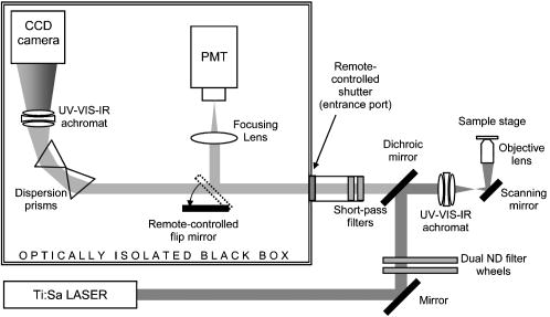 Fig. 2Measured optical transmission of the (a) dichroic mirror (Laseroptik, Garbsen, Germany), (b) color filter set (total ; BG-40, Schott, Mainz, Germany), and (c) dispersion prism, including Fresnel reflection losses (sample thickness: , Herasil 1, Heraeus, Hanau, Germany). (d) Quantum efficiency of the CCD (Princeton Instruments, Spec-10:2KBUV, , ST-133 controller; typical read noise 3 e-rms at digitization). 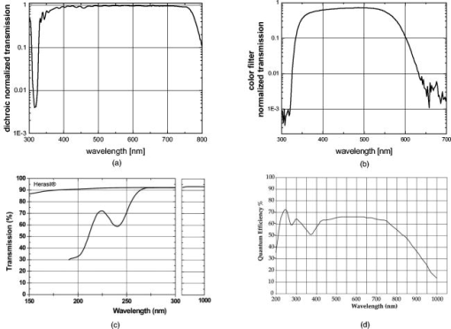 The emission passed through a dichroic mirror (Laseroptik, Garbsen, Germany) and was filtered by a set of short-pass Schott optical glass filters (total ; BG-40, Schott, Mainz, Germany) [see Figs. 2a and 2b for the transmission curves]. These filters were fitted onto the entrance port of an optically isolated “black box” that houses the spectrograph and a photomultiplier tube (H7422P-40, Hamamatsu Photonics, Hamamatsu City, Japan) for lifetime imaging. The lifetime imaging system is based on a four-timegate fluorescence lifetime module (LiMo, Nikon Instruments Europe BV, Badhoevedorp, The Netherlands) and is described in detail elsewhere.28 Because the acquisition time of a spectral image was , the LiMo was used for fast acquisition of images (excitation power , pixel dwell time ) during focusing onto the sample. The filtered light entering the black box was dispersed by two prisms and focused on the CCD camera by another UV-VIS-IR achromat ( , focal ; Bernhard Halle Nachfl., Berlin, Germany). Each prism (Herasil 1, Heraeus, Hanau, Germany) has a flat optical transmission of more than 93% over the spectral range of . The spectrograph was equipped with a thermoelectrically cooled, back-illuminated CCD camera (Princeton Instruments, Spec-10:2KBUV, , ST-133 controller, typical read noise 3 e-rms at digitization). The CCD chip is long in the dispersion direction (horizontal) and high (vertical) and has square pixels. This UV anti-reflection coated CCD is specially designed to have high detection efficiency in the UV [Fig. 2c]. The spectral measurements were carried out on a small subarea of the CCD chip of high and long. To gain acquisition speed, the subarea was positioned at the corner of the CCD chip closest to the readout node. The total readout time for a full spectrum was . The pixel clock pulses generated by the in-house built laser scanning head were used to synchronize the scanning with the CCD camera controller. The main factors that affect the spectral resolution of the spectral imaging microscope are: the resolution of the objective lenses, the dispersion of the prism, the total optical magnification, and the pixel size of the CCD camera. In addition, the maximum achievable resolution depends on the number of pixels binned in the dispersion direction (see Fig. 3 ). The air objective ( tube length, Fluor, Nikon, Japan) was estimated to have a lateral resolution of and an axial resolution of . These values were calculated using an excitation wavelength of . The point-spread function (PSF) of the system was measured experimentally by recording three-dimensional (3-D) images (data not shown) of 35 fluorescent latex beads ( diameter, yellow-green beads, Polysciences, Warrington, Pennsylvania) in 2% low-melting-point agarose gel that contained a lipid emulsion (1% Intralipid) that creates the same scattering properties as that of skin tissue. A slight increase in lateral PSF values was observed with the measurement depth, while the increase in axial PSF with depth was relatively larger. Lateral PSFs of and axial PSFs of were measured at varying depths up to . The total optical magnification of the system amounted to . Therefore, the back-projected size of the PSF on the CCD chip amounted to (CCD pixel dimension is square pixels). Combined with the dispersion of the prisms [Fig. 3a], this yields a theoretical resolution between at and at . Fig. 3(a) Spectral bandwidth per CCD pixel of the spectral imaging system for 100 wavelength channels and 800 wavelength channels (no binning). Also depicted are the NIR excitation bandwidth [ , full-width at half-maximum, (FWHM)], second-harmonic generation (SHG) bandwidth ( , FWHM), and Nyquist bandwidth to resolve an SHG emission peak ( , FWHM). (b) Spectral responsivity of the spectral imaging system, excluding the collection efficiencies of the objective. 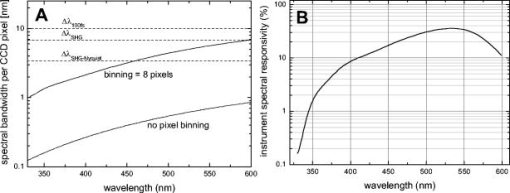 The spectral resolution of the spectral imaging system was experimentally verified using Ar-Ion laser lines (Fig. 4 ). The spot size of the laser lines at the detector amounted to at most FWHM. This sets a limit on the maximum achievable spectral resolution of 0.8, 0.94, and (FWHM) at wavelengths of 457.9, 488.0, and , respectively. 4.Calibration of the InstrumentWavelength calibration of the CCD was done by using a calibrated monochromator. A white light source was placed before the monochromator and a single-mode fiber optic cable at the exit port. The slit width was set to for both ports. The other end of the fiber was placed at the focal point of the objective lens. A pinhole was placed at the image plane of the microscope objective (tube ) to align the fiber. The pixel values were recorded for ten wavelength settings from . Utilizing the built-in calibration option of the CCD camera software (WinSpec/32), the peak positions were fitted using a fifth-order polynomial with the spectral bandwidth per pixel shown in Fig. 3a. The calibration was verified using an Hg(Ne) spectral calibration lamp (Model 6034, Oriel Instruments, Stratford, Connecticut). Typically, the calibration accuracy was better than over the whole wavelength range. Following the spectral responsivity (flatfield) calibration procedure in a previous work,29 we measured the fluorescence emission spectra of of quinine sulfate in perchloric acid using the multiphoton spectral imaging setup. The output of a blackbody radiation source was used to measure the spectral responsivity at lower wavelengths. The spectral responsivity of the system is depicted in Fig. 3b. Note that in this figure, the transmission of the objectives are shown, but the collection efficiencies of the objectives are not taken into account. 5.Spectral Data Analysis Software ProgramSoftware was developed in IDL 6.0 (Research Systems, Inc., Boulder, Colorado) for analyzing the 100-channel spectral data. The software program, SPECview2003, enables analysis of the spectral data, including visualization of a single image channel, obtaining spectra from a single image pixel or a region of interest (ROI), subtraction of background spectral profiles (from dark regions in the image), integration of wavelength channels, and exporting images as TIFF files. 6.Results on Ex Vivo Human Skin and In Vivo Mouse SkinHuman skin biopsy samples were snap-frozen in liquid nitrogen and stored at . The cryosections for fluorescence analysis and imaging were cut with thickness. These tissue sections were cut perpendicular to the epidermal layer so that each section comprised a complete transverse cross section of the epidermal and dermal layers. The tissue sections were kept unstained and mounted onto glass slides for microscopic two-photon (2P) excited autofluorescence (AF) and second-harmonic generation (SHG) imaging and analysis under the spectrographic microscope. For comparison, the tissue sections were then stained for histopathological examination. The measured pixel-averaged emission spectrum of an unstained fixed human (arm) skin biopsy section is shown in Fig. 5c , inset. The spectra shown here were corrected for the wavelength-dependent sensitivity. The average emission spectrum depicts two main emission bands: the high-intensity peak at and a weak broad emission between and that peaks at . The peak at corresponds to SHG; its peak is located at exactly half of the excitation wavelength, and its spectral width corresponds to of the laser excitation . The broad emission originates from the autofluorescence of various endogenous fluorophores such as NAD(P)H, keratin, flavins, melanin, lipids, elastin, and collagen.3 The measured autofluorescence spectrum of the human skin biopsy [Fig. 5c, inset] is observed to be red-shifted compared to the confocal autofluorescence spectra obtained previously on freshly excised epithelial tissues using and laser light where the measured emission peak is at (Refs. 22, 30, 31). The difference is likely to be due to the different nature of the tissue. On the other hand, our results are found to be in agreement (peak positions and shape) with previously measured two-photon excited autofluorescence spectra of human skin ex vivo.12, 32 Fig. 5(a) Widefield microscope image of a human (arm) skin section prepared using Elastica Verhoeff-Van Gieson staining showing the different tissue layers. (b) Spectrum-integrated spectral image of the human skin section before staining. (c) Measured pixel-averaged emission spectra of the skin tissue layers and (inset) of the entire spectral image, showing the intense SHG and the weak AF. The laser excitation wavelength is , the laser excitation power is , and the objective is air ( tube, Fluor, Nikon, Japan). ; generation; ; ; ; ; . Scale . 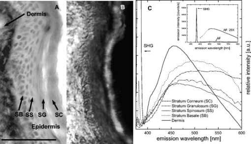 The pixel-averaged spectrum of each layer of the skin can be obtained using the ROI option of the SpecView2003 software, and the results are shown in Fig. 5c. Each spectrum is an average of spectra in an ROI derived from the spectral image in Fig. 5b. The spectrum of the dermis shows high SHG (peak not shown in the plot) emissions due to the presence of collagen fiber structures. Also, a fluorescence signal that peaks at with a small hump feature at around is observed in the dermal spectrum. In a previous study, we attribute this peak to nonlinear Raman scattering in collagen.4 For the in vivo imaging study, female inbred albino hairless mice (SKH1- , Charles River, Someren, Netherlands) were examined. The experimental protocol was approved by the Committee on Animal Research of the Erasmus University Rotterdam. Prior to the experiments, animals were fed on a diet free of chlorophyll (Hope Farms BV, Woerden, Netherlands) for a minimum of two weeks in order to remove the autofluorescence emission from mouse skin centered at attributed to pheophorbide-a.33 Before imaging, the mouse was anaesthetized using intraperitoneal injection of Hypnorm, (Janssen Pharmaceutica, Tilburg, Netherlands) and diazepam, . These injections were repeated every hour until the end of the experiment. The duration of the experiment was not more than . To prevent dehydration, the mouse was also injected intraperitoneally with of 0.9% sterile NaCl solution. The mouse was placed on a temperature-controlled microscope stage and a coverslip. A visualization method was developed that results in images that contain the image intensity information as well as the spectral information. RGB real-color visualization involves transformation of the high-resolution spectral information to a lower-resolution RGB color space. RGB real-color imaging uses colors that are associated to a particular wavelength in the visible range . The details of the transformation algorithm are described elsewhere.4 Figure 6 shows RGB real-color representation of the nonlinear spectral images from living mouse tissue at different depths from below the skin surface using a excitation light, air objective ( tube length, Fluor, Nikon, Japan), at a constant average power of . Photo-bleaching was not observed at this low power level. All images are and fields of view are . The images in Fig. 6 represent sections that contain morphological structures most relevant to the study of skin. The spectral imaging system can typically image as deep as . The system’s ability to image deep structures is limited by emission attenuation due to scattering in the tissue and spherical aberrations introduced by the index of refraction mismatch between the sample and the objective.At depths beyond , low intensity and degraded resolution characterize the spectral images (data not shown). Fig. 6(a) to (h) RGB real-color visualization of spectral images of live mouse skin measured at increasing depths relative to the skin surface. (i) to (l) Average emission spectra at depth of and below depicting the SHG broadening. The laser excitation wavelength is , the laser excitation average power for all depths is , and the objective is air. All images are , and the fields of view are acquired at per image. Scale . (Color online only.) 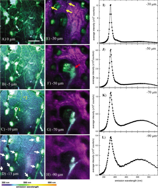 At relative depths of , green fluorescent blobs and striations are observed [Figs. 6a and 6b]. Polygonal structures most likely to be corneocytes (dead skin cells) are also discernable. Corneocytes comprising the stratum corneum, are rich in lipids, particularly in their apices. At a depth of , cellular structures (diameter ) start to emerge with bluish cytoplasm and dark blue nuclei [Fig. 6c]. In previous studies, it has been suggested17 that the main source of intracellular autofluorescence is NAD(P)H. This is fluorescent only when reduced and has a characteristic blue fluorescence peak at . Another source of redox-related autofluorescence comes from cellular flavins.17 In contrast to NAD(P)H, these molecules are fluorescent in their oxidized state and have a characteristic yellow fluorescence peak at . A deeper section in the skin shows higher cell density in the same image area [Fig. 6d]. The cells appear smaller in cross section (diameter ) than the cells in Fig. 6c. This is because these cells are more columnar in shape, while the cells near the stratum corneum are flattened out. Hair follicles appear as round green-fluorescing structures [Fig. 6d, white arrows]. Hair follicles are known to be mainly composed of keratin and melanin, with the latter fluorescing at . These hair follicles, mostly inactive in these hairless mice, are also visible at deeper depths. Purple, fiber-like structures are observed at a depth of . The purple color refers to the second-harmonic signal generated by collagen. This is a clear indication that the cells in Fig. 6d are mostly basal cells of the epidermis near the dermal-epidermal interface. Also, blue fluorescent dermal cells are observed [Fig. 6e, yellow arrows]. It is well known that the dermis is largely composed of extracellular matrix molecules collagen and elastin. Additionally, small densities of cells are known to be found in the mouse dermis. A recent immunofluorescence study has identified dermal macrophages as the major population, of nucleated cells in the mouse dermis.34 Small populations of dermal dendritic cells (DC), migrating Langerhans cells (LC), and fibroblasts are also found in mouse dermis.35 Fibroblasts are responsible for the production of skin structural proteins such as collagen, elastin, and glucosaminoglycans.36 At a depth of , a bluish-green structure emerges [Fig. 6f red arrow]. This could be either a sebaceous gland or a dermal cyst, which is a remnant of disintegrated hair follicles found on hairless mice. The resolution of the image apparently degrades at depths of . Shown in Fig. 7 are single-pixel spectra corresponding to pixels 1 and 2, as depicted in Fig. 6 (c, black and yellow asterisks). Pixels 1 and 2 are obtained in hair follicle and cellular cytoplasm regions, respectively. At this depth of , typical signal-to-noise ratios (SNRs) at the peak of the spectra in the hair follicle regions are , while SNR values in the cellular regions are typically . The decrease in overall signal results in the SNR degradation with increasing imaging depth. For instance, we observed a drop in the measured SNR values in collagen fiber regions (the signal pertains to SHG) from to measured at depths of and , respectively. Fig. 7Single-pixel spectra corresponding to pixels 1 and 2 as depicted in Fig. 6c. Pixels 1 and 2 are obtained in the hair follicle and cellular cytoplasm regions, respectively. Typical signal-to-noise ratio (SNR) values in the hair follicle regions are , while SNR values in the cellular regions are typically . 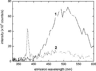 7.DiscussionThe work presented in this paper described the design and implementation of a nonlinear spectral imaging system. The results showed that nonlinear spectral imaging can be implemented for thin tissue samples as well as thick living tissue samples. Here, real-color representation was used to visualize the spectral images. This resulted in the exceptional capability to discriminate tissue layers and components without the use of any stain or fluorescent label (Figs. 5 and 6). Aside from RGB color representation, other visualization methods can be used to visualize the high-resolution spectral images. For example, dual-channel image visualization can be used to produce a color overlay image of the SHG and the autofluorescence. This visualization offers a simple manner of discriminating between the dermis, comprised mainly of collagen fibers that produce SHG, and the epidermis, containing cells that produce autofluorescence. Other visualization methods that are expected to show interesting results are spectral clustering and classification mapping and spectral unmixing. Although we have shown the capability of the nonlinear spectral imaging system to produce in-depth images, there are still a number of challenges that need to be addressed. Presently, the system is capable of producing images up to depths of , and we are currently making efforts to improve the maximum achievable imaging depth. The spectral imaging system described was specifically designed for in-depth spectral imaging of autofluorescence. Crucial to the high sensitivity is the lack of an entrance aperture for the spectrograph. This enables inclusion of scattered fluorescence light in the detection signal at the price of degradation of the spectral resolution at increased depths. Only a few systems have been previously described that can be used for in-depth in vivo spectral imaging of autofluorescence. A multiple bandpass filter-based system was recently described that was used for ex vivo human skin spectral imaging.12 Here, filters with a bandwidth of were used, and no spectral degradation with depth is expected. However, multiple acquisition passes are required to record spectral images that affect sensitivity and acquisition times. Moreover, spectral resolution is somewhat limited. Our system yields a resolution of up to depth (see Fig. 8 ). Moreover, spectral images are recorded in a single pass, and light exposure of the specimen, and thus photo-induced damage, are reduced. Our system also employs a high-sensitivity CCD camera compared to a lower-sensitivity PMT. Currently, commercial two-photon spectral imaging systems have become available (e.g., Zeiss LSM 510, ). Here, a multi-anode PMT is used in combination with gratings, and a spectral resolution of is specified.2 Such systems in principle should be applicable for in-depth in vivo imaging. This is hampered, however, by limitations due to low quantum efficiency of PMT and low transmission in the blue and UV spectral regions of the optics. Importantly, these setups will be affected by scattering and index of refraction mismatch-induced aberration in similar ways to our system. Fig. 8Spectral bandwidth (FWHM) (squares) and normalized spectrum-integrated intensity (integrated from ; triangles) of the SHG signal at varying depths. The dermal-epidermal boundary is at (dashed line). 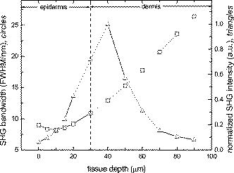 Scattering is the major factor that limits the maximum achievable imaging depth by decreasing the number of excitation photons reaching the focus area as well as decreasing the number of emission photons collected by the objective lens.37 This results in the degradation of the quality of the in-depth images. An attempt to boost the number of emitted photons at the focal area by increasing the excitation power or extending the exposure time may lead to excessive photo-bleaching and initiate photo-toxic effects on the living specimen.38, 39 Two-photon photo-bleaching studies on endogenous fluorophores have shown, however, that NIR femtosecond excitation intensity levels less than do not result in significant photo-bleaching or photo-toxic effects in living cells.4, 38, 39, 40 The efficiency of collecting the diffused fluorescence deep within tissues also plays a role in the determination of the maximum achievable imaging depth. Studies have shown that most high-magnification commercial microscopes lose a significant fraction of the two-photon fluorescence by clipping the divergent cone of light emitted from the objective back aperture.41, 42 The numerical aperture (NA) of the objective influences the overall detected signal and the maximum achievable imaging depth. Objectives with the highest available NA are typically used in two-photon imaging to produce the smallest spot size, greatest peak intensity, and greatest collection efficiency. In highly scattering tissues, there is a trade-off between the spatial resolution and the increased attenuation by the use of high NAs. Here, large-angle excitation rays are more likely to be scattered than central rays because they travel a longer distance to the focus, resulting in a reduction of the effective NA with increasing depth in scattering tissue. Hence, the optimal situation is to use a lower NA for excitation and a high NA to collect the emission, which could be accomplished by means of underfilling the microscope objective in the back focal plane.37, 43 At increasing imaging depths, the refractive index mismatch-induced spherical aberration results in loss of detected fluorescence signal and broadening of the excitation PSF leading to the degradation of the image spatial resolution.44, 45 Water immersion microscope objectives are typically used in imaging of cells in aqueous environments with refractive index very close to 1.33. However, the choice of immersion objective for use in tissue imaging is complicated by the variation of refractive indices of typical tissue specimens. For example, it has been shown that the refractive index varies significantly with different layers of the skin: the index of refraction was found to be 1.47 in the stratum corneum, 1.43 in the stratum granulosum, 1.34 in the stratum basale, and 1.41 in the upper dermis.46 It has recently been shown that at depths beyond the skin epidermis, an oil immersion objective collected 10% more autofluorescence than a water immersion objective .47 Limitations on the maximum achievable imaging depth introduced by tissue-induced spherical aberrations can be improved by reducing the NA of the objective. Furthermore, advanced techniques can be implemented to correct spherical aberrations. Adaptive optics systems offer a solution to the problem of tissue-induced aberrations. A number of adaptive optical imaging systems that implement dynamic aberration correction have been demonstrated using a deformable membrane mirror48 or a deformable mirror.49, 50 The lack of an aperture of the spectral imaging system contributes a high sensitivity for in-depth imaging. However, it also results in the degradation of the spectral resolution at deep tissue sections. In our setup, the projected beam pattern of the emission onto the CCD is significantly broadened at increased depth. This is evident in the measured SHG spectra [Figs. 6i, 6j, 6k, 6l] and measured SHG spectral bandwidth at deep tissue sections (Fig. 8, squares). In principle, both the broadening of the excitation PSF and the inclusion of scattered emission due to absence of an entrance aperture are likely to contribute to the spreading of the projected emission beam onto the CCD. The, former, however, was found to have minimal influence on the spectral resolution of the nonlinear spectral imaging system, and the collected scattered emission by the objective to the “apertureless” spectrograph contributes mainly to the loss in resolution of the system at increasing depths. 8.SummaryThe developed nonlinear spectral imaging system is capable of producing spectral images with: (1) spectral sensitivity in the wavelength range of (1.2% to 27% responsivity, excluding objective collection efficiency); (2) spectral resolution of up to depth; (3) lateral and axial spatial resolutions of and (using a air objective), respectively; and (4) spectral image acquisition times of (spectral image wavelength channels, CCD pixel dimension is square pixels). Our initial results on human skin biopsy imaging further demonstrate that the spectral imaging system is capable of producing high-quality images. The developed spectral image analysis software, SpecView2003, proved to be a valuable tool in obtaining spectra from various regions-of-interest (ROIs). This capability to obtain ROI spectra from spectral images revealed differences in emission spectra between human tissue layers. This work has also demonstrated that tissue-intrinsic emission spectral imaging is capable of resolving fine structures within thick tissues. Similar to previous multiphoton studies on tissues,17, 23, 51, 52 we were able to observe cellular structures in the epidermis and the extracellular matrices in the dermis. Our work, however, is unique in its use of pixel-by-pixel emission spectrum to enhance the contrast between biochemically different structures. This distinct feature of the imaging method enabled us to observe and discriminate dermal cells from collagen and elastin. AcknowledgmentsThis work is part of the Physics for Medical Technology Research Program of the Stichting voor Fundamenteel Onderzoek der Materie [FOM, financially supported by the Nederlandse Organisatie voor Wetenschappelijk Onderzoek (NWO)]. ReferencesT. Haraguchi,
T. Shimi,
T. Koujin,
N. Hashiguchi, and
Y. Hiraoka,
“Spectral imaging fluorescence microscopy,”
Genes Cells, 7
(9), 881
–887
(2002). https://doi.org/10.1046/j.1365-2443.2002.00575.x 1356-9597 Google Scholar
T. Zimmermann,
J. Rietdorf, and
R. Pepperkok,
“Spectral imaging and its applications in live cell microscopy,”
FEBS Lett., 546
(1), 87
–92
(2003). https://doi.org/10.1016/S0014-5793(03)00521-0 0014-5793 Google Scholar
J. A. Palero,
H. S. de Bruijn,
A. van der Ploeg-van den Heuvel,
H. J. C. M. Sterenborg, and
H. C. Gerritsen,
“Spectrally resolved multiphoton imaging of in vivo and excised mouse skin tissues,”
Biophys. J., 93
(3), 992
–1007
(2007). 0006-3495 Google Scholar
J. A. Palero,
H. S. de Bruijn,
A. van der Ploeg-van den Heuvel,
H. J. C. M. Sterenborg, and
H. C. Gerritsen,
“In vivo nonlinear spectral imaging in mouse skin,”
Opt. Express, 14
(10), 4395
–4402
(2006). https://doi.org/10.1364/OE.14.004395 1094-4087 Google Scholar
R. C. Ecker,
R. de Martin,
G. E. Steiner, and
J. A. Schmid,
“Application of spectral imaging microscopy in cytomics and fluorescence resonance energy transfer (FRET) analysis,”
Cytometry A, 59
(2), 172
–181
(2004). Google Scholar
E. Kahn,
A. Vejux,
D. Dumas,
T. Montange,
F. Frouin,
V. Robert,
J. M. Riedinger,
J. F. Stoltz,
P. Gambert,
A. Todd-Pokropek, and
G. Lizard,
“FRET multiphoton spectral imaging microscopy of 7-ketocholesterol and Nile Red in U937 monocytic cells loaded with 7-ketocholesterol,”
Anal Quant Cytol. Histol., 26
(6), 304
–313
(2004). 0884-6812 Google Scholar
T. Zimmermann,
J. Rietdorf,
A. Girod,
V. Georget, and
R. Pepperkok,
“Spectral imaging and linear unmixing enables improved FRET efficiency with a novel GFP2-YFP FRET pair,”
FEBS Lett., 531
(2), 245
–249
(2002). https://doi.org/10.1016/S0014-5793(02)03508-1 0014-5793 Google Scholar
Y. Hiraoka,
J. R. Swedlow,
M. R. Paddy,
D. A. Agard, and
J. W. Sedat,
“Three-dimensional multiple-wavelength fluorescence microscopy for the structural analysis of biological phenomena,”
Semin. Cell Biol., 2
(3), 153
–165
(1991). 1043-4682 Google Scholar
L. Melton,
“Imaging: the big picture,”
Nature (London), 437
(7059), 775
–779
(2005). 0028-0836 Google Scholar
J. M. Larson,
“The Nikon C1si combines high spectral resolution, high sensitivity, and high acquisition speed,”
Cytometry A, 69A
(8), 825
–834
(2006). Google Scholar
R. Lansford,
G. Bearman, and
S. E. Fraser,
“Resolution of multiple green fluorescent protein color variants and dyes using two-photon microscopy and imaging spectroscopy,”
J. Biomed. Opt., 6
(3), 311
–318
(2001). https://doi.org/10.1117/1.1383780 1083-3668 Google Scholar
L. H. Laiho,
S. Pelet,
T. M. Hancewicz,
P. D. Kaplan, and
P. T. C. So,
“Two-photon 3-D mapping of ex vivo human skin endogenous fluorescence species based on fluorescence emission spectra,”
J. Biomed. Opt., 10
(2), 024016
(2005). 1083-3668 Google Scholar
J. M. Vroom,
K. J. De Grauw,
H. C. Gerritsen,
D. J. Bradshaw,
P. D. Marsh,
G. K. Watson,
J. J. Birmingham, and
C. Allison,
“Depth penetration and detection of pH gradients in biofilms by two-photon excitation microscopy,”
Appl. Environ. Microbiol., 65
(8), 3502
–3511
(1999). 0099-2240 Google Scholar
L. Rigacci,
R. Alterini,
P. A. Bernabei,
P. R. Ferrini,
G. Agati,
F. Fusi, and
M. Monici,
“Multispectral imaging autofluorescence microscopy for the analysis of lymph-node tissues,”
Photochem. Photobiol., 71
(6), 737
–742
(2000). 0031-8655 Google Scholar
E. S. Wachman,
W. Niu, and
D. L. Farkas,
“AOTF microscope for imaging with increased speed and spectral versatility,”
Biophys. J., 73
(3), 1215
–1222
(1997). 0006-3495 Google Scholar
Z. Malik,
M. Dishi, and
Y. Garini,
“Fourier transform multipixel spectroscopy and spectral imaging of protoporphyrin in single melanoma cells,”
Photochem. Photobiol., 63
(5), 608
–614
(1996). 0031-8655 Google Scholar
B. R. Masters,
P. T. C. So, and
E. Gratton,
“Multiphoton excitation fluorescence microscopy and spectroscopy of in vivo human skin,”
Biophys. J., 72 2405
–2412
(1997). 0006-3495 Google Scholar
Y. C. Wu,
P. Xi,
J. N. Y. Qu,
T. H. Cheung, and
M. Y. Yu,
“Depth-resolved fluorescence spectroscopy of normal and dysplastic cervical tissue,”
Opt. Express, 13
(2), 382
–388
(2005). https://doi.org/10.1364/OPEX.13.000382 1094-4087 Google Scholar
Y. C. Wu and
J. N. Y. Qu,
“Two-photon autofluorescence spectroscopy and second-harmonic generation of epithelial tissue,”
Opt. Lett., 30
(22), 3045
–3047
(2005). https://doi.org/10.1364/OL.30.003045 0146-9592 Google Scholar
D. Chorvat Jr., J. Kirchnerova,
M. Cagalinec,
J. Smolka,
A. Mateasik, and
A. Chorvatova,
“Spectral unmixing of flavin autofluorescence components in cardiac myocytes,”
Biophys. J., 89
(6), L55
–57
(2005). 0006-3495 Google Scholar
J. V. Rocheleau,
W. S. Head, and
D. W. Piston,
“Quantitative NAD(P)H/flavoprotein autofluorescence imaging reveals metabolic mechanisms of pancreatic islet pyruvate response,”
J. Biol. Chem., 279
(30), 31780
–31787
(2004). https://doi.org/10.1074/jbc.M314005200 0021-9258 Google Scholar
S. Villette,
S. Pigaglio-Deshayes,
C. Vever-Bizet,
P. Validire, and
G. Bourg-Heckly,
“Ultraviolet-induced autofluorescence characterization of normal and tumoral esophageal epithelium cells with quantitation of NAD(P)H,”
Photochem. Photobiol. Sci., 5
(5), 483
–492
(2006). https://doi.org/10.1039/b514801d 1474-905X Google Scholar
W. R. Zipfel,
R. M. Williams,
R. Christie,
A. Yu Nikitin,
B. T. Hyman, and
W. W. Webb,
“Live tissue intrinsic emission microscopy using multiphoton-excited native fluorescence and second harmonic generation,”
Proc. Natl. Acad. Sci. U.S.A., 100
(12), 7075
–7080
(2003). https://doi.org/10.1073/pnas.0832308100 0027-8424 Google Scholar
M. A. Albota,
C. Xu, and
W. W. Webb,
“Two-photon fluorescence excitation cross sections of biomolecular probes from ,”
Appl. Opt., 37
(31), 7352
–7356
(1998). 0003-6935 Google Scholar
W. Mohler,
A. C. Millard, and
P. J. Campagnola,
“Second harmonic generation imaging of endogenous structural proteins,”
Methods, 29 97
–109
(2003). 1046-2023 Google Scholar
C. Xu,
W. Zipfel,
J. B. Shear,
R. M. Williams, and
W. W. Webb,
“Multiphoton fluorescence excitation: new spectral windows for biological nonlinear microscopy,”
Proc. Natl. Acad. Sci. U.S.A., 93 10763
–10768
(1996). https://doi.org/10.1073/pnas.93.20.10763 0027-8424 Google Scholar
M. Bass, Optical Society of America, Handbook of Optics, McGraw-Hill, New York
(1995). Google Scholar
C. J. de Grauw and
H. C. Gerritsen,
“Multiple time-gate module for fluorescence lifetime imaging,”
Appl. Spectrosc., 55 670
–678
(2001). https://doi.org/10.1366/0003702011952587 0003-7028 Google Scholar
J. A. Gardecki and
M. Maroncelli,
“Set of secondary emission standards for calibration of the spectral responsivity in emission spectroscopy,”
Appl. Spectrosc., 52
(9), 1179
–1189
(1998). https://doi.org/10.1366/0003702981945192 0003-7028 Google Scholar
Y. Wu and
J. Y. Qu,
“Combined depth- and time-resolved autofluorescence spectroscopy of epithelial tissue,”
Opt. Lett., 31
(12), 1833
–1835
(2006). https://doi.org/10.1364/OL.31.001833 0146-9592 Google Scholar
Y. Wu and
J. Y. Qu,
“Autofluorescence spectroscopy of epithelial tissues,”
J. Biomed. Opt., 11
(5), 054023
(2006). https://doi.org/10.1117/1.2362741 1083-3668 Google Scholar
J. Chen,
S. Zhuo,
T. Luo,
X. Jiang, and
J. Zhao,
“Spectral characteristics of autofluorescence and second harmonic generation from ex vivo human skin induced by femtosecond laser and visible lasers,”
Scanning, 28
(6), 319
–326
(2006). 0161-0457 Google Scholar
G. Weagle,
P. E. Paterson,
J. Kennedy, and
R. Pottier,
“The nature of the chromophore responsible for naturally occurring fluorescence in mouse skin,”
J. Photochem. Photobiol., B, 2
(3), 313
–320
(1988). https://doi.org/10.1016/1011-1344(88)85051-6 1011-1344 Google Scholar
M. Dupasquier,
P. Stoitzner,
A. van Oudenaren,
N. Romani, and
P. J. Leenen,
“Macrophages and dendritic cells constitute a major subpopulation of cells in the mouse dermis,”
J. Invest. Dermatol., 123
(5), 876
–879
(2004). 0022-202X Google Scholar
K. W. Baker,
S. McKee-Protopapas, and
J. E. Habowsky,
“The Langerhans cell in hairless mouse epidermis,”
Scan Electron Microsc., 457
–465
(1983)
(0586-5581) Google Scholar
P. T. C. So,
H. Kim, and
I. E. Kochevar,
“Two-photon deep tissue ex vivo imaging of mouse dermal and subcutaneous structures,”
Opt. Express, 3
(9), 339
–350
(1998). 1094-4087 Google Scholar
A. K. Dunn,
V. P. Wallace,
M. Coleno,
M. W. Berns, and
B. J. Tromberg,
“Influence of optical properties on two-photon fluorescence imaging in turbid samples,”
Appl. Opt., 39
(7), 1194
–1201
(2000). https://doi.org/10.1364/AO.39.001194 0003-6935 Google Scholar
G. H. Patterson and
D. W. Piston,
“Photobleaching in two-photon excitation microscopy,”
Biophys. J., 78
(4), 2159
–2162
(2000). 0006-3495 Google Scholar
M. G. Nichols,
E. E. Barth, and
J. A. Nichols,
“Reduction in DNA synthesis during two-photon microscopy of intrinsic reduced nicotinamide adenine dinucleotide fluorescence,”
Photochem. Photobiol., 81
(2), 259
–269
(2005). https://doi.org/10.1562/2004-08-05-RA-263.1 0031-8655 Google Scholar
S. Huang,
A. A. Heikal, and
W. W. Webb,
“Two-photon fluorescence spectroscopy and microscopy of NAD(P)H and flavoprotein,”
Biophys. J., 82
(5), 2811
–2825
(2002). 0006-3495 Google Scholar
M. Oheim,
E. Beaurepaire,
E. Chaigneau,
J. Mertz, and
S. Charpak,
“Two-photon microscopy in brain tissue: parameters influencing the imaging depth,”
J. Neurosci. Methods, 111
(1), 29
–37
(2001). https://doi.org/10.1016/S0165-0270(01)00438-1 0165-0270 Google Scholar
E. Beaurepaire,
M. Oheim, and
J. Mertz,
“Ultra-deep two-photon fluorescence excitation in turbid media,”
Opt. Commun., 188 25
–29
(2001). https://doi.org/10.1016/S0030-4018(00)01156-1 0030-4018 Google Scholar
F. Helmchen and
W. Denk,
“Deep tissue two-photon microscopy,”
Nat. Methods, 2
(12), 932
–940
(2005). 1548-7091 Google Scholar
G. J. de Grauw,
J. M. Vroom,
H. T. M. van der Voort, and
H. C. Gerritsen,
“Imaging properties in two-photon excitation microscopy and effects of refractive-index mismatch in thick specimens,”
Appl. Opt., 38
(28), 5995
–6003
(1999). 0003-6935 Google Scholar
W. Lo,
Y. Sun,
S.-J. Lin,
S.-H. Jee, and
C.-Y. Dong,
“Spherical aberration correction in multiphoton fluorescence imaging using objective correction collar,”
J. Biomed. Opt., 10
(3), 034006
(2005). https://doi.org/10.1117/1.1924614 1083-3668 Google Scholar
A. Knuttel and
M. Boehlau-Godau,
“Spatially confined and temporally resolved refractive index and scattering evaluation in human skin performed with optical coherence tomography,”
J. Biomed. Opt., 5
(1), 83
–92
(2000). https://doi.org/10.1117/1.429972 1083-3668 Google Scholar
C. Y. Dong,
B. Yu,
P. D. Kaplan, and
P. T. So,
“Performances of high numerical aperture water and oil immersion objective in deep-tissue, multi-photon microscopic imaging of excised human skin,”
Microsc. Res. Tech., 63
(1), 81
–86
(2004). https://doi.org/10.1002/jemt.10431 1059-910X Google Scholar
M. J. Booth,
M. A. A. Neil,
R. Juskaitis, and
T. Wilson,
“Adaptive aberration correction in a confocal microscope,”
Proc. Natl. Acad. Sci. U.S.A., 99
(9), 5788
–5792
(2002). https://doi.org/10.1073/pnas.082544799 0027-8424 Google Scholar
L. Sherman,
J. Y. Ye,
O. Albert, and
T. B. Norris,
“Adaptive correction of depth-induced aberrations in multiphoton scanning microscopy using a deformable mirror,”
J. Microsc., 206
(1), 65
–71
(2002). https://doi.org/10.1046/j.1365-2818.2002.01004.x 0022-2720 Google Scholar
P. Marsh,
D. Burns, and
J. Girkin,
“Practical implementation of adaptive optics in multiphoton microscopy,”
Opt. Express, 11 1123
–1130
(2003). 1094-4087 Google Scholar
A. Zoumi,
A. Yeh, and
B. J. Tromberg,
“Imaging cells and extracellular matrix in vivo by using second-harmonic generation and two-photon excited fluorescence,”
Proc. Natl. Acad. Sci. U.S.A., 99
(17), 11014
–11019
(2002). https://doi.org/10.1073/pnas.172368799 0027-8424 Google Scholar
P. J. Campagnola,
A. C. Millard,
M. Terasaki,
P. E. Hoppe,
C. J. Malone, and
W. A. Mohler,
“Three-dimensional high-resolution second-harmonic generation imaging of endogenous structural proteins in biological tissues,”
Biophys. J., 81 493
–508
(2002). 0006-3495 Google Scholar
|

