|
|
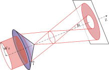
1.IntroductionOptical microscopy is an important investigative tool for micron-and submicron-level objects in a wide variety of fields. Darkfield microscopy, which requires special illumination of specimens by blocking out the central light and allowing only those rays converging at oblique angles to strike the specimen and observing the scattered lights from the specimen, is an effective method for revealing edges and boundaries of samples in some circumstances in contrast with brightfield microscopy. The brightly illuminated specimen that appears on a black background greatly increases the specimen’s contrast and visibility. Heger 1 utilized darkfield microscopy in orthogonal polarized spectral imaging for studying endovascular laser–tissue interactions in vivo. Liu 2 combined darkfield microscopy with a multispectral microscopic imaging system for the detection of single-particle scattering spectroscopy of individual plasmonic nanostructures. Curry and coworkers3 realized epi-illumination through a microscope objective applied to darkfield imaging and the microspectroscopy of nanoparticle interaction with cells. In the conventional darkfield illumination unit shown in Fig. 1a “spider stop” is used in front of the condenser to block out the central light to form a hollow cone of light. The light at the apex of the cone is focused at the plane of the specimen and spreads again into an inverted hollow cone. The objective lens sits in the hollow of this cone. Because the divergence angle of the hollow cone is greater than the objective’s aperture angle, no directly illuminated rays enter the objective. The specimen’s image is made only by the scattered light. The main shortcoming of this method is that the “spider stop” blocks most of the illuminating light and results in ineffective illumination. We propose a solution to this problem by using an axicon, which is a conical lens that produces a line focus rather than a point focus from the incident collimated beam. It has been found in many applications such as optical trapping,4, 5 plasma waveguide,6, 7 two-photon fluorescence microscopy,8 radially polarized beam generation,9 etc. Curry 3 used an axicon to form a ring light and used the microscopic objective to illuminate both the specimen and the image by the backscattered light. This approach is suitable for reflective darkfield illumination, but a field stop is needed to reduce the background noise, accordingly decreasing illumination at the center of the image and introducing haze from diffraction. Our approach applies a transmittive darkfield illumination scheme that does not suffer from these limitations. We use an axicon combined with a pair of lens substituting for the “spider stop” and collect the forward scattered light for imaging. Alternatively, a diode laser is introduced to excite fluorescence and a fiber spectrometer is used to gather the scattering and fluorescence spectra of microsized samples. This system integrates the capabilities of microspectrophotometer, fluorescence microscope, darkfield microscope, and even brightfield microscope. 2.ExperimentsThe axicon is a wavefront division optical element. As Fig. 2a shows, collimated beam incident on the base of the axicon is deviated cylindrically toward the optical axis due to refraction. Behind the axicon, two zones must be distinguished. The first zone, just after the axicon, is the spatial interference zone, where all refracted rays overlap and interfere, resulting in a nondiffracted Bessel beam.10, 11 Beyond this zone, all deviated rays independently propagate along different directions and form a hollow cone of a beam with a ringshape of intensity distribution on a cross-sectional plane. Considering the light transmittance, the open angle is usually designed to be very small (less than 10°), giving a good approximate calculation of the divergence angle , where is the refractive index of the axicon. It is obvious that the beam divergence angle from a single axicon is too small to meet the requirements of darkfield illumination, that is, the aperture angle of the illuminating beam must be larger than that of the objective to ensure that only the scattered light enters the objective. To solve this problem, we put a pair of lens ( and ) behind the axicon to enlarge the aperture angle of illumination. Fig. 3 illustrates the geometrical arrangement and parameters of the optical path. According to the Gaussian formula of geometrical optics, it is not difficult to derive the following equations: where is the final divergence angle of the illuminating beam, and and are the focal lengths of and . In our experiment, the radius of the collimated beam is , the open angle and refractive index of the axicon are and , and , , , and . Substituting these parameters into Eq. 1 results in , which is bigger than the aperture angle of most dry objectives (e.g., the aperture angle of 25X objective/ is 23.6°, 40X objective/ is 40.5°). From Eq. 1, it can be seen that the final divergence angle is adjustable by moving the position of lens between the axicon and lens (i.e., changing and simultaneously), provided other parameters are fixed. When is adjusted less than the aperture angle of the objective, the illuminating light can enter the objective, thereby realizing brightfield microscopy.Fig. 3Plane geometrical arrangement and parameters of a collimating beam passing through an axicon and a pair of lens.  Fig. 4 shows the experimental layout of our system. The white light from a halogen lamp is coupled into a fiber bundle that is in diameter and is collimated by a short focal lens. The collimated light is deviated by the axicon, passes through a long focal length lens , and is then reflected by a mirror directing it into a short focal length lens to form a hollow cone of light focusing on the plane of the specimen. By adjusting the position of lens , darkfield and brightfield microscopy can be implemented and converted easily. The diode laser (Power Technology Inc., USA) working at a wavelength of and an output power of , after beam expanding and collimating, is directed by a beamsplitter into the same light path as the white illumination light, to excite the sample's fluorescence. Two crossed linear polarizers and are employed to eliminate the background noise and increase the image’s contrast. A fiber spectrometer with a spectral resolution of in the wavelength range of (Solar Laser Systems Inc., Belarus) is used to measure the scattering or fluorescence spectra of the sample. The objective both images and collects spectra. The probe end of the fiber spectrometer is set to be conjugated with the specimen plane and is symmetrically positioned with the CCD-sensor target with respect to the beamsplitter . Thus, the spectral sampling area is at the center of the imaging field, whose diameter is , where is the magnification of the objective and is the fiber’s core diameter. 3.Results and DiscussionThis section demonstrates the multiple functions of the integrated apparatus. Fig. 5 shows the photomicrographs of particles in brightfield and darkfield illumination, respectively, by manually adjusting the position of lens . In the brightfield situation [Fig. 5a], the feature of the surface of the particles is not well defined. But in the case of darkfield illumination [Fig. 5b], more details are presented and the image acquires an apparent three-dimensional appearance. The scattering spectrum of an individual particle circled at the center of the image is captured and plotted in Fig. 5c, which uses a 25X objective to obtain the spectral sampling area, which is in diameter. Fig. 6 presents three micrographs of yeast cells imaged by a 25X objective, respectively, in brightfield and darkfield illumination. In the darkfield case [Figs. 6b and 6c], the function of the polarizers and is revealed. Fig. 6b is captured without using and . A bright background is observed, which comes from the directly illuminated light because of the undesired curvature at the tip of the axicon.12 Utilizing the characteristic of the scattered light from an object illuminated by a linearly polarized light having an altered polarization direction, we can reduce the effect by using two crossed linear polarizers. is used to polarize the illuminating light. , whose transmission axis is orthogonal to that of ’s, is placed in front of the CCD camera for filtering off the undesired directly illuminated light. As shown in Fig. 6c, where the two crossed polarizers are used, the bright background is apparently diminished and the contrast of the image is increased. This is also effective in the fluorescence microscopy. Figure 7 shows the fluorescence images and the fluorescence spectrum of ZnS particles excited by the diode laser. Because the excitation laser beam diverges from the axicon and cannot enter the objective, no fluorescence filter is needed. An obvious background noise is observed in Fig. 7a, where no polarizers are used. This also results from the undesired curvature at the tip of the axicon. Curry 3 reduced this problem by introducing a field stop preceding the axicon to prevent light from reaching the tip. But the negative aspects arise from the decrease in the illumination at the center of image and introduce haze from diffraction at the edge of the field stop. Here we solve this problem by using the two crossed polarizers, and . As shown in Fig. 7b, this approach obtains a clear and high-contrast fluorescence image. Fig. 7c is the measured fluorescence spectrum of the center circled particle, where a 10X objective is used and the spectra sampling area is in diameter. The peak wavelength of the fluorescence of the ZnS particle is around . The overshooting high peak at a wavelength is a partial leakage of the excitation light. Fig. 5Photomicrographs and scattering spectrum of particles. (a) Brightfield image; (b) darkfield image; (c) scattering spectrum of the center circled individual particles in (b). 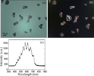 Fig. 6Comparison of brightfield and darkfield images of yeast cells. (a) Brightfield image; (b) darkfield image without using polarizers and , (c) darkfield image obtained using crossed polarizers and .  Fig. 7Fluorescence images and fluorescence spectrum of ZnS particles excited by the diode laser. (a) Fluorescence image with background noise without using polarizers and , (b) clear fluorescence image using crossed polarizers and , (c) fluorescence spectrum of an individual particle circled at the center of (b).  4.ConclusionsWe have proposed an approach to implementing-darkfield and fluorescence microscopy using an axicon and have demonstrated the multiple functions of the integrated apparatus. Our system combines the capability of a microspectrophotometer with the darkfield and fluorescence microscopes, which can get the scattering or fluorescence spectra of samples at a micronlevel while simultaneously viewing the sample. The advantages of our system are the high transmittance of the illuminating flux (nearly 100%), the high contrast of the image, and the convenient toggle between darkfield and brightfield microscopies. AcknowledgmentsThis work is supported by the National Science Foundation of China under Grant nos. 60678023 and 60337020. ReferencesM. Heger,
J. F. Beek,
K. Stenback,
D. J. Faber, and
M. Gemert,
“Darkfield orthogonal polarized spectral imaging for studying endovascular laser-tissue interactions in vivo—a preliminary study,”
Opt. Express, 13 702
–715
(2005). https://doi.org/10.1364/OPEX.13.000702 1094-4087 Google Scholar
G. L. Liu,
J. C. Doll, and
L. P. Lee,
“High-speed multispectral imaging of nanoplasmonic array,”
Opt. Express, 13 8520
–8525
(2005). https://doi.org/10.1364/OPEX.13.008520 1094-4087 Google Scholar
A. Curry,
W. L. Hwang, and
A. Wax,
“Epi-illumination through the microscope objective applied to darkfield imaging and microspectroscopy of nanoparticle interaction with cells in culture,”
Opt. Express, 14 6535
–6542
(2006). https://doi.org/10.1364/OE.14.006535 1094-4087 Google Scholar
V. G. Chavez,
D. McGloin,
H. Melville,
W. Sibbett, and
K. Dholakia,
“Simultaneous micromanipulation in multiple planes using a self-reconstructing light beam,”
Nature (London), 419 145
–147
(2002). https://doi.org/10.1038/nature01007 0028-0836 Google Scholar
J. Arlt,
V. G. Chavez,
W. Sibbett, and
K. Dholakia,
“Optical micromanipulation using a Bessel light beam,”
Opt. Commun., 197 239
–245
(2001). https://doi.org/10.1016/S0030-4018(01)01479-1 0030-4018 Google Scholar
J. Fan,
T. R. Clark, and
H. M. Milchberg,
“Generation of a plasma waveguide in an elongated high repetition rate gas jet,”
Appl. Phys. Lett., 73 3064
–3066
(1998). https://doi.org/10.1063/1.122673 0003-6951 Google Scholar
E. W. Gaul,
S. P. Le Blanc,
A. R. Rundquist,
R. Zgadzaj,
H. Langhoff, and
M. C. Downer,
“Production and characterization of a fully ionized He plasma channel,”
Appl. Phys. Lett., 77 4112
–4114
(2000). https://doi.org/10.1063/1.1329323 0003-6951 Google Scholar
P. Dufour,
M. Piché,
Y. D. Koninck, and
N. McCarthy,
“Two-photon excitation fluorescence microscopy with a high depth of field using an axicon,”
Appl. Opt., 45 9246
–9252
(2006). https://doi.org/10.1364/AO.45.009246 0003-6935 Google Scholar
Y. Kozawa and
S. Sato,
“Generation of a radially polarized laser beam by use of a conical Brewster prism,”
Opt. Lett., 30 3063
–3065
(2005). https://doi.org/10.1364/OL.30.003063 0146-9592 Google Scholar
R. M. Herman and
T. A. Wiggins,
“Production and uses of diffractionless beams,”
J. Opt. Soc. Am. A, 8 932
–942
(1991). 0740-3232 Google Scholar
M. Lei and
B. Yao,
“Characteristics of beam profile of Gaussian beam passing through an axicon,”
Opt. Commun., 239 367
–372
(2004). https://doi.org/10.1016/j.optcom.2004.05.048 0030-4018 Google Scholar
D. Benoit,
V. Philippe, and
H. Daniel,
“Characterization and modelling of the hollow beam produced by a real conical lens,”
Opt. Commun., 211 31
–38
(2002). https://doi.org/10.1016/S0030-4018(02)01900-4 0030-4018 Google Scholar
|