
|
|
1.IntroductionPhotoacoustic imaging is a hybrid imaging modality with excellent optical absorption contrast and high resolution beyond the optical ballistic and quasiballistic regimes ( in scattering biological tissues).1 It has become a rapidly growing field in biomedical research because of its great potential in breast cancer diagnosis,2, 3 skin melanoma detection,4, 5, 6 and functional brain imaging.7, 8 High imaging speed is essential for biomedical research involving dynamics and is highly desirable for decisionmaking in clinics. However, photoacoustic imaging systems using a single-element ultrasound transducer are limited in speed by mechanical scanning. To improve imaging speed, several groups have employed ultrasound arrays for photoacoustic imaging.9, 10 For example, using a ultrasound array, Niederhauser 9 obtained an imaging speed of 7.5 B-scan-frames/s with resolution. Althrough ultrasound arrays of clinical diagnostic ultrasound frequencies (several megahertz) are commercially available, arrays of high frequencies are still at the research stage. We developed a photoacoustic microscopy system with a high-frequency ultrasound array,11 which provided axial and lateral resolutions. Real-time B-scan imaging capability was demonstrated.12 Besides high imaging speed, 3-D imaging is also highly desirable. One advantage of 3-D imaging is to provide maximum amplitude projection (MAP) images in various orientations. Another advantage is the ability to view images interactively. The flexibility to rotate, scale, and view the region of interest from various perspectives can facilitate visualization. We present a fast 3-D dark-field reflection-mode photoacoustic microscopy system with a ultrasound linear array. This system performs realtime cross-sectional (B-scan) imaging at (faster than the video rate) with real-time beamforming and 3D imaging of 166 B-scan frames at with postbeamforming. To enable dark-field reflection-mode photoacoustic imaging, we designed a novel light delivery system consisting of both fiber and free-space optic components. The dark-field laser pulse illumination configuration was known to have advantages in suppressing undesirable photoacoustic signals from the superficial layers of the skin.4 Three-dimensional photoacoustic images of the subcutaneous vasculature in rats were demonstrated in vivo, which matched well with their ex vivo transmission optical microscopy counterparts. Our photoacoustic microscopy system is also presented as a compact prototype for handheld operation and is anticipated to accelerate preclinical and clinical applications of photoacoustic imaging. 2.MethodsA schematic of the system is shown in Fig. 1 . Our system consists of a diode-pumped Q-switched Nd:YLF laser, a tunable dye laser, a ultrasound linear array, custom receive and control electronics, an eight-channel PCI data acquisition (DAQ) card, a multicore PC, a custom-designed light delivery system, and a motorized linear motion actuator. 2.1.Optics and Light DeliveryAs the irradiation source, the tunable dye laser (Cobra, Sirah Laser-und Plasmatechnik GmbH, Germany) was pumped by the Nd:YLF laser (INNOSLAB, Edgewave GmbH, Germany). The Nd:YLF pump laser had a pulse duration of and a pulse energy of at . The continuous optical pumping from the diode stacks in this Q-switched Nd:YLF laser provided the flexibility of external triggering on demand at rates up to without compromising the pulse energy. This feature offered a significant advantage over flashlamp-pumped Q-switched lasers, which are typically maintained at a fixed low pulse repetition rate (e.g., ). Rhodamine 6G laser dye was used to enable a peak output of per pulse with a pulse width of at the wavelength from the dye laser, with a tuning range. For our imaging experiments, we used the peak wavelength. This wavelength also corresponds to an isosbestic point where oxy- and deoxy-hemoglobin have equal molar extinction coefficients. Proper delivery of laser light into biological tissues for photoacoustic excitation is crucial to achieving a high signal-to-noise ratio (SNR) in photoacoustic imaging. The light delivery system was designed to provide a compact photoacoustic imaging device with sufficient SNR and robust performance. The dye laser output was coupled into a -core-diameter multimode optical fiber and collimated by a fiber collimator at the output end of the fiber. A free-space optic setup, integrated with the ultrasound array, was used to guide light further (Fig. 1). The collimated light beam, of diam and energy, was split into two beams by a 50:50 nonpolarizing beamsplitter. The two beams were reflected by mirrors toward two cylindrical lenses and coupled into a plastic slab. The thick plastic slab, with a hollow cylindrical core for the ultrasound probe, was polished for light transmission. During experiments, the cylindrical space was filled with water and sealed by a piece of thin low-density polyethylene (LDPE) film fixed by an o-ring. In total, of the light energy reached the surface of the film. Because of finite fiber aperture the final optical illumination patterns on the skin surface were thick-line shaped, as shown in Fig. 1. The length and width of each illumination area were 6 and , respectively. Dark-field laser pulse illumination was achieved through fine tuning the mirrors and cylindrical lenses, reducing the photoacoustic signals from the superficial paraxial area. However, a large dark-field area may reduce the optical fluence reaching the targeted area. The optimal illumination radius was estimated to be using the concept of effective attenuation coefficient,13 the exponential decay rate of fluence far from the source, with typical tissue parameters. Consequently, leaving a width right below the array elements as the dark field gives approximately the best performance. In practice, the mirrors and cylindrical lenses were finely tuned to optimize the SNR. The optical fluence on the skin surface was estimated to be per pulse, well below the ANSI recommended maximum permissible exposure (MPE) of for a single pulse. We acquired data in —50 frames for realtime B-scan imaging or 166 frames for 3-D imaging; the time-averaged light intensity during this was (the total illuminated surface area for one 3-D image was due to the mechanical scanning), also below the ANSI recommended MPE calculated as ( in seconds).14 For prolonged illumination, the ANSI-recommended MPE for average light intensity would be lower. However, for prolonged illumination during B-scan imaging, we can either pause a few seconds between acquisitions or slow down the frame rate. We also expect to reduce the delivered energy with improved SNR by system optimization. The ANSI safety limit for this pulse width region is dominantly based on the thermal mechanism; thus, our compliance to the ANSI standards guarantees no thermal damage to the tissue. 2.2.Ultrasound Array and BeamformingWe used a unique ultrasound linear array fabricated from a 2-2-piezocomposite by the NIH Resource Center for Medical Ultrasonic Transducer Technology at the University of Southern California.15 The array had 48 elements (of dimensions ) with spacing. The dimension of the element in the elevation direction was , and the elements were focused in this direction with a fixed focal length of , which provides a resolution of in the elevation direction within the focal zone. The pulse-echo insertion loss and element cross-talk were 19.1 and , respectively. The mean fractional bandwidth was 50% for pulse-echo operation, which translates to for receiving-only operation, as used in our present photoacoustic imaging system. Althrough ultrasound beamforming traditionally has used dedicated hardware,16, 17 we instead used multicore processors (Dell Precision 490 with two Quad core Xeon processors), which allows off-the-shelf personal computers to perform the task and offers programming flexibility. Microsoft Visual Studio 2005 Professional Edition and Microsoft XNA Game Studio in the Visual Studio C# 2005 Express Edition environment were used to develop the software for dynamic receive beamforming and display. Details on implementation of multithreaded parallel programming and GPU-based scan conversion and display in this software beamforming can be found elsewhere.12 2.3.Data Acquisition and Volume ImagingPhotoacoustic signals picked up by the ultrasound array were amplified by a custom-built radio-frequency (RF) board with a variable gain and were down-multiplexed to eight channels, which were digitized at 125 megasamples per second using a 8-channel PCI DAQ card (Octopus CompuScope 8389, GaGe Applied Systems, USA). The card was used as the master clock for the entire system and programmed to send trigger signals to the multiplexer control and laser. The repetition rate was set at , which was the highest rate that the laser could work without degradation of pulse energy. We used linear scanning to achieve 3-D imaging. During the scanning, the array translated linearly over the skin surface, so that the B-scan imaging planes were all parallel to each other. This was accomplished by mounting the light delivery system and the ultrasound array in a linear motion actuator (KR20, THK Co. Ltd., Japan). A bipolar stepper motor (4118S, Lin Engineering, USA) controlled by a microstep stepper motor controller (BC2D15, Peter Norberg Consulting, Inc., USA) was used to drive the linear motion actuator. The scanning system provided sufficient precision for our use. Six laser shots were needed to obtain one B-scan image because of the 6:1 down-multiplexing in our data acquisition. To produce one 3-D image, 166 B-scan frames were acquired in , corresponding to 996 laser shots at a repetition rate. During the data acquisition, the array scanned continuously at a constant speed . The speed was set so that the distance the array traveled during each B-scan time period was , less than the ultrasonic focus in the elevational direction . Although the linear motion actuator was fixed on an optical table for scanning, handheld operation was also possible. More user-friendly handheld operation for daily clinical use can be achieved by shrinking the size of the light delivery and scanning systems through custom manufacturing. While real-time B-scan imaging was demonstrated at ,12 postbeamforming after data acquisition reached . This higher speed was due to less hardware communication. In postbeamforming, a B-scan movie was first played, and an MAP of the acquired 3-D image was then displayed for preview immediately. In total, was needed for a user to view an MAP image, representing the fastest speed among reported photoacoustic imaging systems. The user might choose to either replay the B-scan movie or display a contrast-enhanced MAP image processed by a Dynamic-link Library written in MATLAB (Math Works, Inc., USA). All these operations could be done online by simply clicking corresponding buttons on a graphic user interface generated by the C# program. 3.ResultsThe spatial resolution of our system was characterized by imaging -diam carbon fibers in water. The axial, lateral, and elevational resolutions (at normal depth from the transducer surface) were estimated to be 25, 70, and , respectively. The imaging depth was demonstrated to be in scattering biological tissues. To demonstrate the system’s capability to image blood vessels in vivo, we imaged the upper dorsal region of a Sprague Dawley rat (Harlan Sprague Dawley, Inc., USA), in weight. The rat was anesthetized by intramuscular injection of a mixture of Ketamine and Xylazine . The hair in the imaged region was removed with commercial hair-removal lotion before imaging. Acoustic coupling gel was applied to improve acoustic coupling between the animal and the LDPE film. After the experiment, the rat recovered normally, without noticeable health problems. All experimental animal procedures were carried out in compliance with approved protocols. Figure 2 shows an in vivo MAP photoacoustic image and an ex vivo transmission optical microscopic image of the subcutaneous vasculature in an imaged area. The photoacoustic image is a gray-level plot of the maximum amplitude of the envelope of each time-resolved (A-scan) photoacoustic signal within a depth from the skin. The signals from the skin surface were digitally removed. The transmission optical microscopic photograph , partially overlapping with the photoacoustic image, was acquired ex vivo from the dermal side of the excised skin. As shown in Fig. 2, the vascular distributions matched well between the two images. Vessels shown in the photoacoustic image had diameters varying from . The data acquisition of the photoacoustic image was completed within , and the MAP image was displayed within . An animation of the 3-D image from varying perspectives (Video 1 ) was obtained from postprocessing using VolView (Kitware Inc., USA). Interactive features (rotation, scaling, etc.) were available in VolView as well. Fig. 2In vivo noninvasive MAP photoacoustic image of subcutaneous blood vessels in the upper dorsal region of a Sprague Dawley rat. and represent the mechanical scan and electronic beamforming directions, respectively. The gray scale represents relative optical absorption (arbitrary unit). The regions enclosed by major blood vessels are labeled using A–E. (b) Photograph taken from the dermal side of the excised skin with transmission illumination. The same regions are identified and labeled A–E. The photograph covers most of the photoacoustically imaged region. 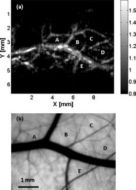 Video 1In vivo 3-D photoacoustic images of the upper dorsal region of a Sprague Dawley rat (QuickTime, 2.66 MB). Video 1.  To validate the system’s reproducibility, we imaged a sacrificed Sprague Dawley rat noninvasively in situ. The experimental procedures were similar to those described above, except that the rat was sacrificed to avoid imaging artifacts due to breathing motion. We repeated scanning the same area (in the lower dorsal region) four times, with a time interval of . The system demonstrated robust performance, with major vessels shown consistently in all four images (Fig. 3 ). 4.Conclusions and DiscussionWe have demonstrated fast 3-D photoacoustic microscopy with a ultrasound linear array capable of realtime B-scan imaging at and 3-D imaging at . To our knowledge, this is the fastest photoacoustic imaging achieved hitherto. The system integrates a novel light delivery system and a motorized linear motion actuator with the ultrasound array, performing scans in elevational direction for 3-D imaging. The light delivery system enables robust reflection-mode imaging, which is applicable to more anatomical sites than orthogonal—or transmission-mode imaging. Optical dark-field illumination is also achieved, reducing the otherwise strong interference of the extraneous photoacoustic signals from the superficial paraxial area. The imaging performance is validated to be robust and reproducible. Previous studies have demonstrated that photoacoustic imaging has great potential in early cancer diagnosis, blood oxygenation mapping, and functional brain imaging. Because of the unique real-time 2-D and fast 3-D imaging capability, our system is anticipated to facilitate many of these biomedical applications. The compact system design also favors clinical practices. Particularly, the promising results shown in this report should motivate future development of photoacoustic microscopy with high-frequency ultrasound arrays toward clinical applications. AcknowledgmentThis work was sponsored, in part, by Grants No. R01 EB000712 and No. R01 NS46214 from the National Institutes of Health. ReferencesL. V. Wang and
H. I. Wu, Biomedical Optics: Principles and Imaging, Wiley, Hoboken, NJ
(2007). Google Scholar
S. Manohar,
S. E. Vaartjes,
J. C. G. van Hespen,
J. M. Klaase,
F. M. van den Engh,
W. Steenbergen, and
T. G. van Leeuwen,
“Initial results of in vivo non-invasive cancer imaging in the human breast using near-infrared photoacoustics,”
Opt. Express, 15 12277
–12285
(2007). https://doi.org/10.1364/OE.15.012277 1094-4087 Google Scholar
S. A. Ermilov,
A. Conjusteau,
K. Mehta,
R. Lacewell,
P. M. Henrichs, and
A. A. Oraevsky,
“128-channel laser optoacoustic imaging system (LOIS-128) for breast cancer diagnostics,”
Proc. SPIE, 6086 68
–79
(2006). 0277-786X Google Scholar
H. F. Zhang,
K. Maslov,
G. Stoica, and
L. V. Wang,
“Functional photoacoustic microscopy for high-resolution and noninvasive in vivo imaging,”
Nat. Biotechnol., 24 848
–851
(2006). https://doi.org/10.1038/nbt1220 1087-0156 Google Scholar
J. T. Oh,
M. Li,
H. F. Zhang,
K. Maslov,
G. Stoica, and
L. V. Wang,
“Three-dimensional imaging of skin melanoma in vivo by dual-wavelength photoacoustic microscopy,”
J. Biomed. Opt., 11 034032
(2006). https://doi.org/10.1117/1.2210907 1083-3668 Google Scholar
R. M. Weight,
J. A. Viator,
P. S. Dale,
C. W. Caldwell, and
A. E. Lisle,
“Photoacoustic detection of metastatic melanoma cells in the human circulatory system,”
Opt. Lett., 31 2998
–3000
(2006). 0146-9592 Google Scholar
X. Wang,
Y. Pang,
G. Ku,
X. Xie,
G. Stoica, and
L. V. Wang,
“Non-invasive laser-induced photoacoustic tomography for structural and functional imaging of the brain in vivo,”
Nat. Biotechnol., 21 803
–806
(2003). https://doi.org/10.1038/nbt839 1087-0156 Google Scholar
S. Yang,
D. Xing,
Y. Lao,
D. Yang,
L. Zeng,
L. Xiang, and
W. R. Chen,
“Noninvasive monitoring of traumatic brain injury and post-traumatic rehabilitation with laser-induced photoacoustic imaging,”
Appl. Phys. Lett., 90 243902
(2007). https://doi.org/10.1063/1.2749185 0003-6951 Google Scholar
J. Niederhauser,
M. Jaeger,
R. Lemor,
P. Weber, and
M. Frenz,
“Combined ultrasound and optoacoustic system for real-time high contrast vascular imaging in vivo,”
IEEE Trans. Med. Imaging, 24 436
–440
(2005). https://doi.org/10.1109/TMI.2004.843199 0278-0062 Google Scholar
D. W. Yang,
D. Xing,
S. H. Yang, and
L. Z. Xiang,
“Fast full-view photoacoustic imaging by combined scanning with a linear transducer array,”
Opt. Express, 15 15566
–15575
(2007). https://doi.org/10.1364/OE.15.015566 1094-4087 Google Scholar
R. Zemp,
M. Li,
R. Bitton,
K. K. Shung,
G. Stoica, and
L. V. Wang,
“Photoacoustic imaging of the microvasculature with a high-frequency ultrasound array transducer,”
J. Biomed. Opt., 12 010501
(2007). https://doi.org/10.1117/1.2709850 1083-3668 Google Scholar
R. J. Zemp,
L. Song,
R. Bitton,
K. K. Shung, and
L. V. Wang,
“Realtime photoacoustic microscopy in vivo with a ultrasound array transducer,”
Opt. Express, 16 7915
–7928
(2008). https://doi.org/10.1364/OE.16.007915 1094-4087 Google Scholar
L. V. Wang,
W. R. Chen, and
R. E. Nordquist,
“Optimal beam size for light delivery to absorption-enhanced tumors buried in biological tissues and effect of multiple beam delivery: a Monte Carlo study,”
Appl. Opt., 36 8286
–8291
(1997). 0003-6935 Google Scholar
The Laser Institute of America, American National Standard for Safe Use of Lasers (ANSI Z136.1–2000),
(2000) Google Scholar
J. M. Cannata,
J. A. Williams,
Q. F. Zhou,
T. A. Ritter, and
K. K. Shung,
“Development of a piezo-composite ultrasound array for medical imaging,”
IEEE Trans. Ultrason. Ferroelectr. Freq. Control, 53 224
–236
(2006). https://doi.org/10.1109/TUFFC.2006.1588408 0885-3010 Google Scholar
K. Wall and
G. R. Lockwood,
“Modern implementation of a realtime 3D beamformer and scan converter system,”
Proc.-IEEE Ultrason. Symp., 2 1400
–1403
(2005). 1051-0117 Google Scholar
C. H. Hu,
X. C. Xu,
J. M. Cannata,
J. T. Yen, and
K. K. Shung,
“Development of a real-time, high-frequency ultrasound digital beamformer for high-frequency linear array transducers,”
IEEE Trans. Ultrason. Ferroelectr. Freq. Control, 53 317
–323
(2006). 0885-3010 Google Scholar
|


