
|
|
1.IntroductionMuch of the laser bioeffects database used to establish the ocular laser exposure guidelines has been obtained from in vivo measurements in nonhuman primate (NHP) eyes. Theoretically, the NHP eye is capable of focusing the collimated light of a laser beam to a spot on the retina of in diameter. However, during laser retinal injury threshold studies, the minimum lesion size observed is much larger than this. Computer modeling1 predicts that the energy required to produce retinal injury will decrease with decreasing retinal irradiance area (i.e., beam spot area) for beam spot diameters down to values approaching the assumed minimal visible lesion size, typically taken to be . Experiments with bovine retinal explants, in which the anterior portions of the eye, including the neural retina, are removed so that the retinal pigmented epithelium (RPE) layer can be directly irradiated, show that indeed the energy required to damage the RPE does decrease with the diameter of the irradiated area for beam spot diameters of and larger.2, 3 The NHP data does not follow the trend predicted by the models and observed in the explant data. Figure 1 shows the retinal beam spot size dependence of the obtained from in vivo NHP measurements. The is defined as that dose having a 50% probability of producing a minimum visible lesion (MVL) on the retina. Note that in Fig. 1 and throughout this paper, the dose is given as the total intraocular energy (TIE), that energy incident at the cornea within the projected area of the ocular pupil, because this quantity can be directly measured for in vivo exposures. Figure 1 includes data from a number of investigations covering a range of laser wavelengths and exposure durations.4, 5, 6, 7, 8 The (TIE) in an intact NHP eye varies only weakly with spot size for retinal beam spot diameters smaller than . Equivalently, the threshold retinal radiant exposure varies inversely as the square of the diameter for small retinal beam spots. For short-duration exposures, the threshold is constant, independent of the diameter of the irradiated area for retinal spot sizes greater than . Note that this “flattening” of the curve is consistent even though the primary damage mechanism changes from a thermal process for the longer duration exposures to a photomechanical or photoacoustical process for the shorter duration exposures.9, 10, 11, 12 Fig. 1versus retinal beam spot diameter for several laser wavelengths and exposure durations. Circles: , (Ref. 4). Squares: , (Refs. 5, 6). Triangles: , (Refs. 5, 6). Inverted triangles: , (Ref. 7). Diamonds: , (Ref. 8). 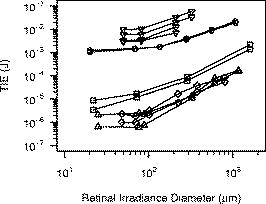 The difference in spot size dependence is illustrated in Fig. 2 , in which values obtained from in vivo NHP measurements and in vitro retinal explant measurements are directly compared. One possible explanation for the discrepancy in the spot size dependence of the retinal damage threshold between the in vivo and in vitro models is that uncompensated refractive error and higher-order aberrations of the dilated eye of an anesthetized NHP significantly affect the quality of focus. Researchers attempt to minimize the impact of these aberrations by selecting subjects having a refractive error within 0.5 or 0.25 diopters from emmetropia. In addition, the diameter of the laser beam entering the eye is kept small, typically 3 or in diameter, so that only the central portions of the focusing elements of the eye are used. However, poorer focus will lead to a larger beam spot size at the retina. Even in the absence of higher-order aberrations, an uncertainty of in refractive error will lead to an uncertainty in the retinal beam spot size that will tend to increase the value of the extracted from the data.13 In the bovine explant measurements, there are no preretinal focusing elements to distort the beam, offering precise control of the beam spot size. Fig. 2Comparison of versus retinal beam spot diameter measured in vivo (NHP, open symbols) and in vitro (bovine explant, closed symbols). For the in vivo data, the is given as the total intraocular energy (TIE). For the in vitro data, the is given as the total incident energy. The dashed lines are the for the in vivo data extrapolated from large spot size to minimum spot size assuming a trend parallel to the in vitro data. Open squares: , (Ref. 4). Open circles: , (Refs. 5, 6). Solid squares: , (Ref. 2). Solid circles: , (Ref. 3). 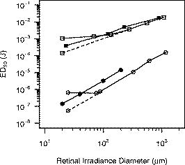 To test this hypothesis, a method to compensate for the aberrations of the NHP eye is required. Adaptive optics (AO), utilizing a deformable mirror in a closed loop with a wavefront sensor, has been used to correct for ocular aberrations to improve the resolution of retinal images14, 15, 16, 17 and to investigate visual function and supernormal vision.14, 18 We have incorporated an adaptive optics system into a standard retinal exposure setup used to measure laser retinal injury thresholds. The adaptive optics system compensates for aberrations of the eye by predistorting the wavefront of the laser beam incident to the eye. The distorted beam is focused onto a spot on the retina that more closely approaches the diffraction limit imposed by the size of the pupil. The for laser-induced retinal injury was measured for and exposures at . Measurements were made with and without wavefront correction and compared. Furthermore, measurements were made with a small-diameter beam and a large-diameter beam incident at the eye. Ocular aberrations will lead to a poorer focus of the large-diameter beam than of the small-diameter beam.19 Therefore, the large-diameter beam should exhibit a larger difference between the measured with and without wavefront correction. 2.MethodMeasurement of the for exposures was performed first. Improvements to the experimental setup and procedure were made based on experience gained from this experiment before performing the exposure duration measurements. 2.1.SubjectsThe for exposures at was measured in cynomolgous monkeys (Macaca fascicularis). The for exposures at was measured in rhesus monkeys (Macaca mulatta). Animals were screened to ensure clear ocular media and normal retinas. The selected subjects were required to have a refractive error less than 0.5 diopters from emmetropia. Each animal was sedated using an intramuscular injection of ketamine hydrochloride and then anesthetized using Propofol administered intravenously. A retrobulbar injection of Lidocaine was used to reduce ocular movement during the exposures. Cycloplegia and full pupil dilation were induced using Proparacaine, Phenylephrine, and Tropicamide. A lid speculum held the eye open for exposure. The cornea was periodically irrigated with a saline solution to maintain clarity. 2.2.Exposure Setup2.2.1.Uncorrected exposuresThe measurement of the for exposures for the uncorrected beam (no wavefront correction) was carried out using a standard retinal laser exposure setup, illustrated in Fig. 3 . Fig. 3Diagram of the setup for performing the duration uncorrected exposures. T: beam expanding telescope. A: aperture. NDF: neutral density filters. M: movable mirror. 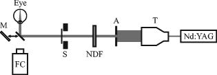 A continuous-wave (CW) beam was obtained from a Spectra-Physics Millenia Pro frequency-doubled Nd:YAG laser (Spectra-Physics, Mountain View, Calfornia). After passing through a beam-expanding telescope, the central portion of the beam was selected using a circular aperture. An electronic shutter was used to produce pulses of duration. Exposures were made with a highly collimated “small” and “large” diameter beam. A aperture was used to produce the small-diameter beam. This beam had a uniform, or “top hat” intensity profile, with a divergence of . The large-diameter beam, produced with a aperture, also had a uniform intensity profile, but a divergence of . Since the fully dilated pupil of the cynomolgous monkey eye was measured to be in diameter, the exposure beams were not clipped by the iris in passing through to the interior of the eye. The beam was directed into the subject eye by a front surface mirror mounted on a translation stage just in front of a fundus camera. The mirror could be moved aside to allow viewing of the retina and then be accurately repositioned for the exposure. The setup was carefully aligned so that the beam entering the eye was collinear with the optical axis of the fundus camera. Retinal target sites could then be designated using the fundus camera crosshair. Neutral density filters (NDF) were used to determine the beam energy for an exposure. Beam calibration and selection of the appropriate NDF for the desired pulse energies was performed by placing a detector at the eye position prior to placing an animal in the setup. The calibration was verified by repeating the calibration procedure after removing the animal from the setup following the planned series of exposures. 2.2.2.Wavefront correctionThe setup used to perform the wavefront-corrected exposures is illustrated in Fig. 4 . Wavefront correction was performed using a Clarifi-3D Closed Loop Adaptive Optical System purchased from AgilOptics (AgilOptics, Inc., Albuquerque, New Mexico). A 37-actuator deformable mirror is controlled by proprietary software running on a personal computer. Feedback is provided by a Hartmann wavefront analyzer (HWA), which consists of a rectangular array of pinhole apertures mounted on a video camera. In the exposure setup, the deformable mirror and the pinhole plate of the HWA are located at positions conjugate to the pupil plane of the subject eye. Fig. 4Setup for performing the duration wavefront-corrected exposures. The setup for performing the exposures was similar. M1 to M13: mirrors. L1 to L4: achromatic doublet lenses. P: pellicle beamsplitter. DBS1: dichroic beamsplitter; reflects at and transmits at . DBS2: dichroic beamsplitter; reflects at and transmits at . BS: beamsplitter. T: beam expanding telescope. A: apertures. NDF: neutral density filters. The reference beam from the diode laser (thin dark line) is directed into the eye. Light from the reference beam reflected off the retina (light gray) exits the eye and is expanded by the first telescope (L1 to L2) to fill the active area of the deformable mirror. Defocus is introduced into this telescope using the optometer combination (M3 to M6). The diameter of the beam is reduced by the second telescope (L3 to L4) to match the entrance of the wavefront sensor. Data from the wavefront sensor is processed by the computer, which controls the shape of the deformable mirror. The exposure beam (dark gray) is introduced into the system by the dichroic beamsplitter (DBS2). The lens L5 is used to compensate for the chromatic difference of refraction of the subject eye for the wavelengths of the reference and exposure beams. The aperture A2 prevents large-angle diffraction from the beam-diameter-defining aperture A1 from entering the setup.  A solid-state diode laser produced the wavelength beam used as the reference beam for the adaptive optics system. This beam was approximately in diameter at the 1/e irradiance point, with a divergence of . To prevent reflections off the cornea from reaching the wavefront analyzer, the reference beam is introduced into the eye near the edge of the pupil (i.e., off the optic axis of the subject eye), but still parallel to the axis of the fundus camera. In order to produce a strong enough signal for the HWA, the reference beam had to be relatively intense. The reference beam used to perform wavefront correction for the exposures typically introduced a total intraocular power (TIP) of . The maximum permissible exposure (MPE)20 for a long-duration cw exposure at corresponds to a TIP of . Light from the reference beam diffusely reflects off the retina and exits the eye in a collimated beam limited by the diameter of the ocular pupil. The beam is expanded by a telescope to fill the active area of the deformable mirror. In Fig. 4, this telescope consists of the optical elements from lens L1 to lens L2. Per manufacturer recommendation, the adaptive optics system was set up with some curvature on the surface of the deformable mirror, allowing the system to make both positive and negative corrections of aberrations. This required that some defocus be deliberately introduced into the telescope. The optometer, consisting of the four mirrors labeled M3, M4, M5, and M6 in Fig. 4, was used for this purpose. Mirrors M4 and M5 were mounted on a translation stage. The optical length of the telescope, and therefore the focus, was altered by adjusting the position of these two mirrors. After reflecting off the deformable mirror, the diameter of the reference beam is reduced to match the entrance aperture of the wavefront sensor by a second telescope, consisting of lenses L3 and L4 in Fig. 4. A beam-splitter directed most of the reference beam light into the HWA. A small portion of the reference beam passes through the beamsplitter and is imaged by a lens onto the detector array of a video camera that was therefore conjugate to the retina of the eye. This provided a means for visually monitoring the performance of the adaptive optics system. The Spectra-Physics laser produced a CW beam. The , pulses were produced using a Continuum Minilite II Q-switched Nd:YAG laser (Continuum, Santa Clara, California). The choice of laser for a given exposure was determined by the position of mirror M10. After passing through a beam-expanding telescope (T), the central portion of the beam was selected using a circular aperture (A1). Aperture diameters were selected to produce a -diam beam at the cornea for the small-diameter exposures, and a -diam beam at the cornea for the large-diameter exposures. Neutral density filters (NDF) were used to determine the pulse energy for the exposure. The shutter determined the exposure duration for the CW laser or selected a single Q-switched pulse from the pulsed laser. After passing through the optics of the exposure system, the -diam beam had a divergence of , and the -diam beam had a divergence of . The lens L5 in Fig. 4 was used to correct for the chromatic difference of refraction of the rhesus monkey eye between the wavelength of the reference beam for the AO system and the wavelength of the exposure beam . Choice of focusing power and position of this lens is discussed in Section 2.3. The wavefront corrected exposures did not include correction for the chromatic difference of refraction of the subject eye. The exposure beam was introduced into the system using the dichroic beamsplitter labeled DBS2. This beamsplitter was highly reflective at , the wavelength of the exposure beam, but transparent at , the wavelength of the reference beam. The beamsplitter therefore did not interfere with the operation of the adaptive optics system, and wavefront correction could continue during the duration of an exposure. The pellicle (P) that directed the reference laser into the eye also deflected a constant proportion of the exposure beam into a reference detector (labeled Detector in Fig. 4). The ratio of the energy at the eye position to the energy at the reference detector was determined and used for dosimetry of the Q-switched exposures. The dichroic beamsplitter DBS1 protected the reference detector from the reference beam. 2.2.3.Uncorrected exposuresThe uncorrected exposures were performed through the wavefront correction setup illustrated in Fig. 4. There was no separate setup to perform the uncorrected exposures, as was the case for the exposures. In order to perform the uncorrected exposures, the deformable mirror was flattened (using the control software), and the optometer (mirrors M3 to M6) was adjusted to produce a collimated beam at the position of the subject eye. 2.3.Compensation of Chromatic AberrationThe reference beam used to measure the aberrations of the subject monkey’s eye had a wavelength of . The adaptive optics system works to provide the best focus (i.e., smallest beam spot diameter) at the retina for light having the same wavelength. The measurement of astigmatism and higher-order aberrations has been shown to be only weakly dependent on the wavelength of the reference beam used.21 However, the ocular medium exhibits significant chromatic dispersion, and the effective focal length of the eye is significantly wavelength dependent. The effective focal length of the rhesus monkey eye is generally taken to be . The adaptive optics system works to bring light of to a focus at this effective distance. The chromatic difference of refraction of the human eye between light of wavelengths and is dipoters.22 If the rhesus monkey eye is assumed to have the same chromatic dispersion as the human eye, then, when the adaptive optics system is working, light of the wavelength will be focused at an effective depth of . The green exposure beam was therefore focused about anterior to the retina. The focus of the green exposure beam can be moved to the same plane as the focus of the reference beam by introducing a small divergence into the exposure beam. The lens L5 in Fig. 4 was used to do this. Lens L5 was placed before the deformable mirror in the optical path of the exposure beam. This location was largely determined by the available space in the setup. Simple geometric ray tracing indicated that a diopter lens at this location would move the focus of the exposure beam to the location of the focus of the reference beam at the retina. The ray tracing prediction was verified by measuring the for a exposure with no lens (0 diopter), a diopter lens, and a diopter lens at the position of L5 in Fig. 4. A diopter lens was not available; lenses were taken from a standard optometrist’s trial lens set. A -diam beam was used, and the adaptive optics system was run to provide wavefront correction during these measurements. A plot of the values obtained is shown in Fig. 5 . Note that data collection continued after this verification process was complete, and therefore Fig. 5 is based on a subset of the final data set used to determine the reported here. The lowest value was indeed obtained using the diopter lens. This lens was therefore used for all subsequent exposures. Fig. 5Verification of the lens used to correct for chromatic difference of refraction between the wavelength of the AO reference beam and the exposure beam for the exposures. The plot shows the for a exposure, expressed as the total intraocular energy, obtained by using a lens of the indicated focusing power at the location L5 of Fig. 4. The adaptive optics system was run to provide wavefront correction for these measurements. For comparison, the obtained without using wavefront correction is included. Error bars indicate the 95% confidence limits. Note that this figure is based on a subset of the final data set, as data collection continued after the verification process was completed. 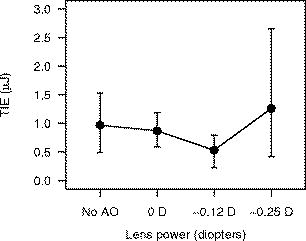 Note that the chromatic aberration compensation was done only for the exposure measurement. The exposure measurements did not include this correction. 2.4.ProcedureThe experiment to measure the for exposures at was completed and analyzed before performing the experiment to measure the for exposures. The general procedure for performing the exposures and analyzing the data was similar for both experiments; specific details are noted here. Prior to performing any exposures in a particular eye, pulses of each from the CW laser were used to place a series of marker lesions in the subject retina. These markers served to define a grid for placing the exposures and to aid in locating the exposure sites during subsequent examination of the retina. The response of the retina to the laser exposures was evaluated at nominally and after exposure. The exposed retinas were photographed using a digital fundus camera and examined visually using an ophthalmoscope. The two examination methods produced nearly identical results. The combination of beam diameter (large/small) and the wavefront correction status (corrected/uncorrected) used for a particular exposure defined the exposure condition. Each eye received exposures for at least two of the beam diameter/wavefront correction combinations. A single dose-response data set for each exposure condition was assembled from the data collected from all eyes. Probit analysis23 was used to extract the from each set of data. 2.4.1.exposuresSix eyes received both uncorrected and wavefront-corrected exposures. An additional four eyes received wavefront-corrected exposures only. All of the uncorrected exposures were performed first, with the wavefront-corrected exposures performed from five to nine weeks after the uncorrected exposures. Four rows of ten exposures were placed in each eye. Each row of exposures was performed using a single exposure condition, and consisted of three exposures to the paramacular region of the retina, then four exposures in the macula, and finally three more paramacular exposures. Exposures in the macular and paramacular regions were processed separately, and values for each combination of beam diameter (large/small), retinal location (macula/paramacula), and wavefront correction status (corrected/uncorrected) were determined. 2.4.2.exposuresTwelve eyes received both uncorrected and wavefront-corrected exposures. All exposures were placed in the macula. Each eye received four to six rows of five exposures. Uncorrected and wavefront-corrected exposures were performed during the same session. Six eyes were exposed using the small-diameter beam ( at cornea), four eyes were exposed using the large-diameter beam ( at cornea), and two eyes received exposures from both the small- and the large-diameter beam. The first six eyes were used to verify the choice of the lens needed to compensate for chromatic dispersion of the rhesus monkey eye (Sec. 2.3). Chromatic compensation was then included in all subsequent wavefront corrected exposures. 3.Results3.1.Threshold for ExposuresTable 1 lists the values obtained for the duration exposures for the six exposure conditions (small/large beam, wavefront corrected/uncorrected, macular/paramacular regions of the retina). values are given for and post-exposure evaluation. Also listed are the 95% confidence limits and the ratios obtained from the probit analysis. In all cases, a smaller was measured when wavefront correction was used. The rightmost column of Table 1 shows the percent decrease in measured with a wavefront-corrected beam relative to the value measured with the uncorrected beam. Table 1ED50 for producing a discernible retinal alteration in the eye of a cynomolgous monkey (Macaca fascicularis) from a 0.1-s duration exposure to laser irradiation of wavelength λ=532nm , measured with and without wavefront correction. Values are expressed as the total intraocular energy (TIE). The rightmost column is the fractional change in the value of the ED50 obtained using wavefront correction relative to the value obtained without wavefront correction.
For the -diam uncorrected beam, we determined the for a exposure at wavelength to be TIE for a macular exposure and TIE for a paramacular exposure. These values are for the observation time. No previous measurement of the for a exposure at has been reported. The for a exposure at in the rhesus monkey (Macaca mulatta) was recently reported to be TIE for a macular exposure and TIE for a paramacular exposure.3 Given the difference in laser wavelength and subject species, we concluded that the measured values reported here are consistent with the earlier data. The values obtained with and without wavefront correction for the exposures are plotted versus the evaluation time in Fig. 6 . For comparison, the measured in the rhesus monkey4 at is included in the plot of the uncorrected beam results. The impact of using wavefront correction in the exposure system is displayed graphically in Fig. 7 . Fig. 6for producing discernible retinal alteration from a exposure to a wavelength laser, expressed as the total intraocular energy (TIE). The is plotted versus the evaluation time ( or ). The retinal location (macula/paramacula) and wavefront correction status (on/off) are indicated. For comparison, the for a exposure at , taken from Ref. 3, is included. Error bars indicate the 95% confidence limits. Points are offset for clarity. Solid circles/solid lines: large-diameter beam, . Open circles/dashed lines: small-diameter beam, . Solid triangles/dotted lines: (Ref. 3). 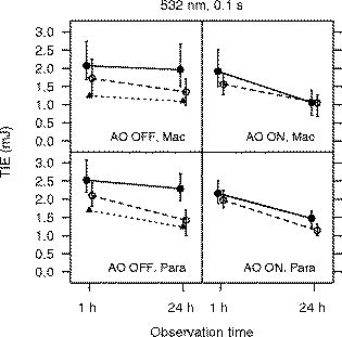 Fig. 7Impact of wavefront correction on measured values for a exposure at . The region of the retina (macula/paramacula) and the evaluation time are indicated. Error bars indicate the 95% confidence limits. Points are offset for clarity. Solid circles/solid line: large-diameter beam. Open circles/dashed line: small-diameter beam. 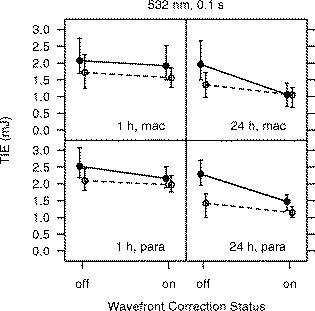 3.2.Threshold for ExposuresTable 2 lists the values determined for the -duration exposures for the four exposure conditions ( -diam beam, wavefront corrected/uncorrected). All exposures were placed in the macula. values are given for and post-exposure evaluation. The wavefront-corrected measurements include compensation for the chromatic difference of refraction between the wavelength of the AO reference beam and the wavelength of the exposure beam . The rightmost column of Table 2 shows the decrease in the obtained using wavefront correction relative to the value obtained with the uncorrected beam. Table 2ED50 for producing a discernible retinal alteration in the macula of a rhesus monkey (Macaca mulatta) from a 3.5-ns pulse at λ=532nm , measured with and without wavefront correction. Values are expressed as the total intraocular energy (TIE).
For the -diam uncorrected beam, we determined the for a exposure at wavelength to be TIE at post-exposure and TIE at . Zuclich 6 reported the for a exposure at to be TIE at post-exposure and TIE at for a macular exposure. The values obtained with and without wavefront correction for the exposures are plotted versus the evaluation time in Fig. 8 . For comparison, the values reported by Zuclich 6 are included in the plot of the uncorrected beam results. Figure 9 shows the impact of using wavefront correction along with chromatic aberration compensation. Fig. 8for producing discernible retinal alteration from a exposure to a wavelength laser, expressed as the total intraocular energy (TIE). The is plotted versus the evaluation time ( or ) for each beam diameter. The left plot shows the obtained using the uncorrected beam. For comparison, the for a exposure at , taken from Ref. 5, is included. The right plot shows the obtained when wavefront correction was used, and correction was made for the chromatic difference of refraction between the wavelengths of the adaptive optics reference beam and the exposure beam . Error bars indicate the 95% confidence limits. Points are offset for clarity. Solid circles/solid lines: -diam. beam. Open circles/dashed lines: -diam. beam. Solid triangles/dotted line: (Ref. 5).  Fig. 9Impact of wavefront correction on measured values for a exposure at . Correction was made for the chromatic difference of refraction between the wavelengths of the adaptive optics reference beam and the exposure beam when wavefront correction was turned on. The evaluation time is indicated. Error bars indicate the 95% confidence limits. Points are offset for clarity. Solid circles/solid lines: -diam. beam. Open circles/dashed lines: -diam. beam.  4.DiscussionAlthough we have no direct measure of the resulting spot size, the results provide evidence that the AO system was indeed compensating to a significant extent for the refractive error and higher-order aberrations of the subject NHP eyes. For all exposure conditions (retinal location, incident beam diameter, exposure duration), the measured while using the AO system was lower than the obtained without using wavefront correction. The reduction in the is more pronounced for the large-diameter beam than for the small-diameter beam. In particular, the obtained for the two beam diameters converge to similar values when wavefront compensation is used (Figs. 7 and 9). The large-diameter beam “samples” more of the ocular aberrations and is expected to result in a more distorted retinal beam spot.19 Effectively correcting for these aberrations should therefore have a more significant impact on the quality of focus of the larger diameter beam. The diffraction-limited spot size is for the beam and for the beam. If diffraction-limited spots were achieved when the AO system was used, the peak retinal irradiance would be higher for the larger-diameter beam, and the obtained using the large-diameter beam would be lower than the obtained from the small-diameter beam. However, the divergence of the beams at the eye after passing through the optical path of the exposure system limits the smallest achievable retinal spot size to no less than about for both beams, even after compensating for all ocular aberrations. The retinal beam spots produced by the large- and small-diameter beams were thus about the same size when the AO system was used to provide wavefront correction. The for laser-induced retinal damage from exposure to a wavelength laser has been measured using small- and large-diameter beams incident at the cornea. The large-diameter beam measurements demonstrate that the adaptive optics system did effectively compensate for refractive error and other ocular aberrations of the NHP eye. However, the is usually measured using a small-diameter beam, in order to minimize the impact of the ocular aberrations. The at the observation point for the beam was measured to be TIE for a , exposure when wavefront correction was used (Table 2). This is 37% smaller than the value of obtained without any compensation for ocular aberrations. In Fig. 2, the dashed lines show an extrapolation of the in vivo NHP data assuming that the continues to decrease with decreasing retinal spot size, as it does for the in vitro retinal explant data. For both sets of data ( , exposures and , exposures), the extrapolated minimum spot is an order of magnitude less than the measured value. If the sole explanation for the flattening of the threshold versus spot size curves (Fig. 2) for small spot sizes is that ocular aberrations lead to a large retinal beam spot size, then correcting for those aberrations would be expected to lead to a reduction in the measured of from the value obtained without correction. This suggests that the ocular aberrations of the anesthetized NHP eye not only might spread the energy of the laser pulse to an area larger than a diffraction-limited spot size, but also might impact the ability to see the small lesions during an ophthalmic examination. Scatter in the ocular media must also be considered. Typically, the inferred from the post-exposure evaluation is smaller than the value extracted from the post-exposure data. This is generally attributed to the difficulty in detecting the smallest damaged areas until metabolic processes related to the injury response mechanism expand the altered area of the retina beyond the initial injury site to an area large enough to be detected via ophthalmoscopic observation. The data presented here follow this trend. For all exposure conditions (retinal location, exposure duration, spot size, AO on/off), the obtained from the observations is less than the obtained from the observations. Furthermore, the relative decrease in the measured with wavefront correction, compared to the value measured without wavefront correction, is less for the data than for the data. This further supports the conclusion that ocular aberrations not only lead to a poorly focused beam, therefore producing a larger than diffraction-limited retinal beam spot, but also negatively impact the ability of an examiner to detect the smallest lesions. For the exposures, the at the observation point for the -diam beam was measured to be TIE when wavefront correction was used, a reduction of 22% from the value of TIE obtained without wavefront correction. However, the measurements for the exposure do not include compensation for the chromatic difference of refraction of the NHP eye between the wavelength of the AO reference beam and the wavelength of the exposure beam . This compensation was included in the exposure measurements (Fig. 5). For a -diam beam, it was found that the dropped from when compensation for chromatic aberration was included in addition to wavefront correction. The was lowered from when compensation for chromatic aberration was included. In both cases, the decrease in is about 38% when compensating for the chromatic difference of refraction. The damage mechanisms are different for the ns-duration and the -duration exposures. Thermal diffusion is not a factor for the exposures but is a significant factor for the duration exposures and may lessen the impact of further improving the focus of the beam using chromatic compensation in addition to wavefront correction for the exposures. However, we can use the exposure results to place an upper limit on the effect of chromatic compensation on the data. Assuming the same impact on the exposure measurements, we can estimate that use of chromatic compensation would at most reduce the for a macular exposure from at the endpoint as listed in Table 1 to TIE. This is a relative reduction of 52% from the value obtained without wavefront correction, . Although the exposure measurements do not include compensation for the chromatic difference of refraction, the measured with wavefront correction is smaller than the measured without such correction. Wavefront correction may not be providing the smallest achievable retinal spot size in this case but is nonetheless improving the concentration of energy at the retina. This research was motivated by a concern that the MPE as provided by current laser safety guidelines20, 24, 25, 26 might not provide an adequate margin of safety for an actively focusing alert eye. We have attempted to more closely approximate such an eye by compensating for the ocular aberrations in the commonly used NHP model. While we did not find an order of magnitude reduction in the as suggested by the trend of the in vitro data, we did find a threshold value for duration, exposures that is lower than any previously reported. The value of the as determined for a MVL detectable after a macular exposure, , is a factor of only 2.6 higher than the MPE for a , visible wavelength exposure ( TIE). 5.ConclusionAn adaptive optics system was incorporated into a laser retinal exposure setup in order to correct for the refractive error and higher-order aberrations of a nonhuman primate eye in order to more closely approximate the exposure conditions experienced by an actively focusing eye in an alert individual. Using this system, the for a , small spot size macular exposure was measured to be TIE, a reduction of 22% from the value of TIE measured without aberration correction. Using wavefront correction, the for a , small spot size macular exposure was measured to be TIE, the lowest measured for a ns-duration exposure. This value is a factor of only 2.6 higher than the MPE for a , visible wavelength exposure. When no correction for ocular aberrations was used, the was measured to be . Use of the adaptive optics system to correct for aberrations reduced the by 37% from this value. The trend of in vitro measurements using bovine retinal explants projects to an one order of magnitude (90%) less than the value obtained from in vivo measurements with no aberration correction (Fig. 2). Distortion of the incident beam by ocular aberrations cannot fully explain the discrepancy between the in vivo measurements and the in vitro results. Other factors such as a limited ability to visually detect threshold retinal lesions in vivo and small-angle forward scatter in the preretinal ocular media must also impact the retinal damage threshold measurement. DisclaimerThe opinions or assertions herein are the private views of the authors and are not to be construed as official or as reflecting the views of Northrop Grumman, the Department of the Army, or the Department of Defense. All animals involved in this study were procured, maintained, and used in accordance with the Animal Welfare Act and the “Guide for the Care and Use of Laboratory Animals” prepared by the Institute of Laboratory Animal Resources, National Research Council, and the ARVO Resolution on the Use of Animals in Research. All experiments involving animals used appropriate levels of anesthesia so that the subjects did not experience pain or distress. AcknowledgmentsThis work was supported by U.S. Air Force Contract F41624-02-D-7003-0015, Task Order 15, titled “Medical Countermeasures for Laser-Induced Eye Injury,” awarded to Northrop Grumman. Task Order 15 is sponsored by the U.S. Army Medical Research Detachment of the Walter Reed Army Institute of Research, Brooks City-Base, Texas. This work was conducted at the U.S. Army Medical Research Detachment, Brooks City-Base, Texas. ReferencesD. J. Lund,
K. Schulmeister,
B. Seiser, and
F. Edthofer,
“Laser-induced retinal injury thresholds: variation with retinal irradiated area,”
Proc. SPIE, 5688 469
–478
(2005). https://doi.org/10.1117/12.608417 0277-786X Google Scholar
K. Schulmeister,
J. Husinsky,
B. Seiser,
F. Edthofer,
H. Tuschi, and
D. J. Lund,
“Explant retinal laser induced threshold studies in the millisecond time regime,”
Proc. SPIE, 6048 6048E1
(2006). 0277-786X Google Scholar
J. Roegener and
C. P. Lin,
“Photomechanical effects—experimental studies of pigment granule absorption, cavitation, and cell damage,”
Proc. SPIE, 3902 35
–40
(2000). https://doi.org/10.1117/12.379339 0277-786X Google Scholar
D. J. Lund,
P. Edsall,
B. E. Stuck, and
K. Schulmeister,
“Variation of laser-induced retinal injury thresholds with retinal irradiated area: duration, exposures,”
J. Biomed. Opt., 12
(2), 023023
–1
(2007). 1083-3668 Google Scholar
J. A. Zuclich,
P. R. Edsall,
D. J. Lund,
B. E. Stuck,
R. C. Hollins,
S. Till,
P. A. Smith,
L. N. McLin, and
P. K. Kennedy,
“Variation of laser-induced retinal damage threshold with retinal image size,”
J. Laser Appl., 12
(2), 74
–80
(2000). 1042-346X Google Scholar
J. A. Zuclich,
P. E. Edsall,
D. J. Lund,
B. E. Stuck,
S. Till,
R. C. Hollins,
P. K. Kennedy, and
L. N. McLin,
“New data on the variation of laser induced retinal-damage threshold with retinal image size,”
J. Laser Appl., 20
(2), 83
–88
(2008). https://doi.org/10.2351/1.2900536 1042-346X Google Scholar
W. T. Ham,
W. J. Geeraets,
H. A. Mueller,
R. C. Williams,
A. M. Clarke, and
S. F. Cleary,
“Retinal burn thresholds for the helium-neon laser in the rhesus monkey eye,”
Arch. Ophthalmol. (Chicago), 84
(6), 797
–809
(1970). 0003-9950 Google Scholar
C. P. Cain,
C. A. Toth,
G. D. Noojin,
D. J. Stolarski,
R. Thomas,
S. Cora, and
B. A. Rockwell,
“Visible lesion threshold dependence on retinal spot size for femtosecond laser pulses in the primate eye,”
J. Laser Appl., 13
(3), 125
–131
(2001). 1042-346X Google Scholar
D. Sliney and
M. Wolbarsht, Safety with Lasers and Other Optical Sources, Plenum Press, New York and London
(1980). Google Scholar
J. Marshall,
“Thermal and mechanical mechanisms in laser damage to the retina,”
Invest. Ophthalmol., 9
(2), 97
–115
(1970). 0020-9988 Google Scholar
J. Marshall,
“Structural aspects of laser-induced damage and their functional implications,”
Health Phys., 56
(5), 617
–624
(1989). 0017-9078 Google Scholar
W. T. Ham,
J. J. Ruffolo,
H. A. Mueller, and
D. Guerry,
“The nature of retinal radiation damage dependence of wavelength, power level, and exposure time,”
Vision Res., 20
(12), 1105
–1111
(1980). https://doi.org/10.1016/0042-6989(80)90047-4 0042-6989 Google Scholar
D. H. Sliney,
J. Mellerio,
V.-P. Gabel, and
K. Schulmeister,
“What is the meaning of threshold in laser injury experiments? Implications for human exposure limits,”
Health Phys., 82
(3), 335
–347
(2002). https://doi.org/10.1097/00004032-200203000-00006 0017-9078 Google Scholar
J. Liang,
D. R. Williams, and
D. T. Miller,
“Supernormal vision and high-resolution retinal imaging through adaptive optics,”
J. Opt. Soc. Am. A, 14
(11), 2884
–2892
(1997). https://doi.org/10.1364/JOSAA.14.002884 0740-3232 Google Scholar
A. Roorda,
F. Romero-Borja,
W. J. Donnelly,
H. Queener,
T. J. Hebert, and
M. C. W. Campbell,
“Adaptive optics scanning laser ophthalmoscopy,”
Opt. Express, 10
(9), 405
–412
(2002). 1094-4087 Google Scholar
F. Romero-Borja,
K. Venkateswaran,
A. Roorda, and
T. Hebert,
“Optical slicing of human retinal tissue in vivo with the adaptive optics scanning laser ophthalmoscope,”
Appl. Opt., 44
(19), 4032
–4040
(2005). https://doi.org/10.1364/AO.44.004032 0003-6935 Google Scholar
R. J. Zawadzki,
S. M. Jones,
S. S. Olivier,
M. Zhao,
B. A. Bower,
J. A. Izatt,
S. Choi,
S. Laut, and
J. S. Werner,
“Adaptive-optics optical coherence tomography for high-resolution and high-speed 3-D retinal in vivo imaging,”
Opt. Express, 13
(21), 8532
–8546
(2005). https://doi.org/10.1364/OPEX.13.008532 1094-4087 Google Scholar
E. J. Fernandez and
P. Artal,
“Study on the effects of monochromatic aberrations in the accommodation response by using adaptive optics,”
J. Opt. Soc. Am. A, 22
(9), 1732
–1738
(2005). https://doi.org/10.1364/JOSAA.22.001732 0740-3232 Google Scholar
P. K. Milsom,
S. J. Till, and
G. Rowlands,
“The effect of ocular aberrations on retinal laser damage thresholds in the human eye,”
Health Phys., 91
(1), 20
–28
(2006). 0017-9078 Google Scholar
(ANSI), American National Standard for Safe Use of Lasers, Z 136.1,
(2007) Google Scholar
L. Llorente,
L. Diaz-Santana,
D. Lara-Saucedo, and
S. Marcos,
“Aberrations of the human eye in visible and near-infrared illumination,”
Optom. Vision Sci., 80
(1), 26
–35
(2003). https://doi.org/10.1097/00006324-200301000-00005 1040-5488 Google Scholar
D. A. Atchison and
G. Smith,
“Chromatic dispersions of the ocular media of human eyes,”
J. Opt. Soc. Am. A, 22
(1), 29
–37
(2005). https://doi.org/10.1364/JOSAA.22.000029 0740-3232 Google Scholar
B. J. Lund,
“The ProbitFit program to analyze data from laser damage threshold studies,”
(2006). Google Scholar
International Commission on Non-Ionizing Radiation Protection,
“Guidelines on limits of exposure to laser radiation of wavelengths between and ,”
Health Phys., 71
(5), 804
–819
(1996). 0017-9078 Google Scholar
International Commission on Non-Ionizing Radiation Protection,
“Revision of guidelines on limits of exposure to laser radiation of wavelengths between and ,”
Health Phys., 79
(4), 431
–440
(2000). https://doi.org/10.1097/00004032-200010000-00013 0017-9078 Google Scholar
International Electrotechnical Commission, IEC 60825–1, Safety of Laser Products—Part 1: Equipment Classification, Requirements and User’s Guide, International Electrotechnical Commission, Geneva
(2001). Google Scholar
|
|||||||||||||||||||||||||||||||||||||||||||||||||||||||||||||||||||||||||||||||||||||||||||||||||||||||||||||||||||||||||||||||||||||||


