|
|
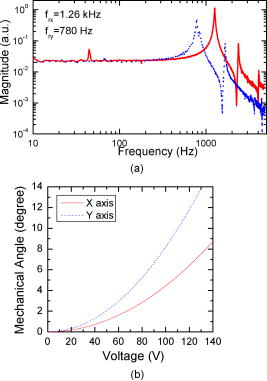
1.IntroductionMultiphoton microscopy (MPM) is an important tool for high-resolution, noninvasive imaging of thick biological tissues.1, 2, 3, 4, 5 MPM utilizes femtosecond lasers to excite nonlinear contrast signals that include two-photon excited fluorescence (TPEF) and second-harmonic generation (SHG). TPEF can be detected from intrinsic sources (e.g., cofactors, proteins) and exogenous fluorophores, while strong SHG signals can be obtained from noncentrosymmetric molecules such as collagen, a common extracellular matrix protein. Thus, MPM can image and distinguish cellular and extracellular matrix structures simultaneously. MPM systems have been mostly developed using free-space optics and microscope platforms. However, for in vivo imaging and clinical applications, a fiber-optic MPM endoscope is desirable where light can be delivered through a flexible fiber and images can be acquired using a miniature probe.6, 7, 8, 9 Delivering femtosecond pulses through fibers and designing miniature scanning probes are two challenges in MPM endoscopy. Double-cladding photonic crystal fibers (DCPCF) have been used by Myaing 10 and Fu,11 where femtosecond pulses were delivered by the single-mode core and MPM signals were collected by the multimode inner cladding of DCPCF. Other groups have used a hollow-core photonic bandgap fiber (PBF) for femtosecond pulse delivery and a separate multimode fiber for MPM signal collection.8, 9 Using different types of miniature scanners, several groups have designed endoscopic MPM systems. Myaing have designed a fiber-optic two-photon endoscope using a piezoelectric tube.12 The scanning endoscope was in diameter. The piezoelectric tube worked at a resonance frequency that restricted the choice of scanning rate. Further reduction of the size of the piezoelectric tube is limited. Microelectromechanical systems (MEMS) is a new technique capable of realizing micro devices, including actuators and mirrors. Fu 13 have designed an MPM endoscopy system using a 1-D MEMS scanner.13 Recently, the same group has demonstrated an MPM probe using a 2-D MEMS scanner.14 However, their MEMS scanners employed electrothermal actuation, and thus the scanning speed was slow with the resonance frequencies of a few hundred Hz. Piyawattanametha 15 have demonstrated an MEMS mirror for MPM application using electrostatic force, and the resonance frequency was increased to . However, the achievable resolution as quantified by the maximum number of resolvable focal spots was limited to on the and axes, due to the limited size and scanning angle of their MEMS mirror. In this paper, we demonstrate an MPM endoscope utilizing a two-axis electrostatic MEMS scanner and DCPCF. A -diam MEMS mirror suitable for MPM imaging is designed. The maximum number of resolvable focal spots of our MEMS scanner is improved to on the and axes. Previously, we have reported the packaging of the MEMS scanner into an MPM probe using a two-lens configuration.16 In this paper, design considerations of the MPM endoscopy system are explored. Critical issues such as characteristics of the MEMS mirror and efficiencies of light delivery and collection in three types of fibers are addressed. Three configurations of probe design are discussed, and their advantages and disadvantages are compared. Last, the performance of the MPM endoscopy system is assessed in fluorescent microspheres and chondrocytes in cartilage. 2.MEMS Mirror DesignA gimbal-less two-axis MEMS mirror was previously reported by Milanović 17 incorporating a small mirror with a diameter of . Smaller MEMS mirrors ( diameters) have been applied to optical coherence tomography (OCT) endoscopy,18, 19 which has lower image resolution than MPM. In this paper, a MEMS scanner with a larger -diam, aluminum-coated mirror is designed to satisfy the high resolution and efficient photon collection requirements imposed by MPM. Special considerations are applied to the MEMS design in order to achieve high speed and wide scanning angle for a large mirror. Our MEMS mirrors use a gimbal-less design. Actuators and mirror apertures are fabricated in separate deep reactive ion etching processes using silicon-on-insulator wafers. This allows respective optimization of the scan angle, maximum scanning speed, and aperture size. Following fabrication, a mirror aperture is bonded to an actuator. Last, the completed scanner is bonded to a package, and the required electrical connections are made employing an ultrasonic wire bonder. Figure 1a shows a scanning electron microscope (SEM) image of a nominal version of a MEMS actuator with a -diam mirror. Four banks of vertical comb-drive fingers provide two degrees of freedom, allowing and axis rotation of a central plate employing electrostatic force. A pedestal and a micromirror are later bonded onto the central plate. The gimbal-less design allows the same fast scanning speed to be achieved for both axes. Independent driving voltages are applied to each electrically isolated bank of vertical comb-drive fingers, while the pedestal and mirror are driven to a relative ground. Therefore, the design eliminates the problems of a slow axis as well as electrical and mechanical cross talk that plague gimbaled structures. Fig. 1(a) SEM image showing a MEMS actuator with a -diam mirror. (b) Photo of a -diam MEMS mirror on a die.  Figure 1b shows a photo of a -diam MEMS mirror designed for MPM endoscopy. The mirror aperture is composed of a low-inertia single-crystal silicon structure consisting of a thin mirror membrane supported by thick stiffening trusses and a tall standoff pedestal . The thin mirror provides minimal inertia for fast scanning, and the tall pedestal accommodates wide scanning angle. The mirror aperture is aluminum coated, in this case, providing a high reflectivity of . In the independent fabrication process, a large mirror can be fabricated and bonded onto the actuator. With this kind of design, a 100% fill factor is possible, where the mirror can take the entire surface with the actuator covered underneath. Therefore, a MEMS mirror with a large mirror size on a small die can be fabricated and optimized for MPM endoscopy. Image resolution of MPM is determined by the focusing capability of a focusing lens and how the back aperture of the lens is filled by a laser beam. If the laser beam diameter is not sufficiently large and the lens is underfilled, the resolution of the endoscope will be low. Therefore, a large beam diameter at the back aperture of the lens is necessary in order to optimally focus light down to a small focal spot. The MEMS mirror is a major component that could limit this beam diameter. The maximum number of resolvable focal spots has been previously used by Piyawattanametha 15 to characterize the resolution limit of MEMS scanners based on diffraction theory. Based on Rayleigh criterion, the maximum number of resolvable focal spots can be calculated as15, 20 where is the optical angle scanning range, is the half angle of the central lobe of the diffraction pattern of the MEMS mirror, is the diameter of the circular MEMS mirror, and is the wavelength. Our MEMS mirror has a diameter of . The maximum optical scanning angle is , which is limited by the height of the pedestal. Therefore, it enables the maximum number of distinguishable focal spots within its scanning range to be on both axes. The overall size of the MEMS scanner used in the endoscopic probe portion of this work is currently not limited by the mirror size but rather the die size of the actuator, which is .Figure 2a shows the frequency response curves of the and axes with the resonance frequencies at and , respectively. Figure 2b shows the mechanical deflection angle versus the driving voltage. The optical scanning angle is twice the mechanical deflection angle. The angle shows a quadratic relationship with respect to the voltage. To achieve a linear scanning, the driving voltage is designed to have a shape of a square root function. 3.Fiber Delivery of Femtosecond PulsesFemtosecond pulses are needed to excite TPEF and SHG signals because they are nonlinear signals that depend quadratically on peak excitation power. However, femtosecond pulses suffer severe chromatic dispersion when propagating in optical fibers and can become broadened to picosecond pulses, thereby deteriorating the excitation efficiency of MPM signals. Therefore, the management of dispersion and proper implementation of dispersion compensation is a critical issue in the design of MPM endoscopy. Here, three types of fibers are tested and their propagation properties characterized: a standard single-mode fiber (SMF), a hollow-core PBF (HC-800-02, Crystal Fiber), and a DCPCF (DC⋅165⋅16⋅Passive, Crystal Fiber), all designed for wavelength operation. To study a worst-case scenario, a light source of pulse width and bandwidth (Femtolasers) is used to test the fibers. Figure 3 shows the pulse width and spectra before and after propagating through the fibers measured by an autocorrelator and a spectrometer. Figures 3a and 3b show the data measured directly from the laser. The pulse width—in this case, —is represented in an interferogram autocorrelation, which can accurately measure the width of ultrashort pulses by the number of fringes. The laser bandwidth is shown to be . Figures 3c and 3d show the pulse width and spectrum after propagating through a SMF. An intensity autocorrelation is measured for the broadened pulses. Figure 3c shows that the pulse is broadened to , which corresponds to a dispersion coefficient of . The spectrum shows a shift and broadening toward the short wavelength side, and the bandwidth is slightly increased to . This phenomenon is possibly induced by the nonlinear effects in SMF.21, 22 Figures 3e and 3f show the pulse-width and spectrum after propagating through a hollow-core PBF. The pulse width is shown to be broadened to , corresponding to a dispersion coefficient of . As expected, the hollow-core PBF exhibits times lower dispersion than SMF because most light propagates in the air core. However, the spectrum bandwidth is reduced to due to its narrow low-loss propagation window. In the DCPCF, there is a solid core that operates as an SMF and an airhole structured inner cladding that functions as a multimode fiber. Femtosecond pulses are lunched into and propagate in the single-mode core, and thus the pulse propagation properties are similar to an SMF. Fig. 3The pulse width and spectra of the laser beam measured before and after propagating through optical fibers. (a) and (b) Directly from the laser. (c) and (d) After propagating through SMF. (e) and (f) After propagating through hollow-core PBF. 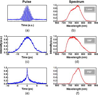 While the excitation efficiency of MPM signals is affected by dispersion and pulse broadening, the collection efficiency of the excited MPM signals is affected by the numerical aperture (NA) of the fibers. For the SMF, the mode field diameter is and the NA is . For the hollow-core PBF, the mode field diameter is also and NA is . For the DCPCF, the single-mode core has a mode field diameter of and NA of , and the multimode inner cladding has a diameter of and NA of . The collection efficiency of the DCPCF can be higher than the other two types of fibers because of the high NA and large diameter of the inner cladding, which can collect MPM signals. Signal attenuation in the SMF and DCPCF is negligible when the fiber length is only , as in endoscopy. However, signal attenuation can be severe in the hollow-core PBF, which has been designed only for a narrow wavelength range of around a center wavelength of . Inside its low-loss window, attenuation is , but outside the window, attenuation increases rapidly. Thus, it has much higher loss than an SMF for short wavelength signals such as TPEF and SHG when excited at an wavelength. To increase collection efficiency, double-cladding fibers have been used by several groups.12, 13, 14 Femtosecond pulses can be launched into the single-mode core of the DCPCF. Both the core and the inner cladding can collect MPM signals. Therefore, the collection efficiency can be largely increased by collecting light with both the core and the high NA inner cladding . The large core size of the DCPCF can also minimize nonlinear effect inside the fiber. In our MPM probe design, we have selected the DCPCF because of its high collection efficiency. Dispersion from the DCPCF can be compensated by a pair of gratings. To minimize the dispersion, we have used a Ti:sapphire laser with pulse width and bandwidth (Mira, Coherent). We have configured a dispersion pre-compensation unit utilizing two gold-coated gratings with (Newport). Figure 4 shows the optical pulses measured directly after the laser, after propagating through a length DCPCF without dispersion precompensation, and after propagating through the same fiber but with dispersion precompensation, respectively. As we can see, the pulse width is from the laser. Dispersion broadens the pulse to when no dispersion precompensation is applied. To compress the pulse width back to the femtosecond regime at the end of the fiber, a grating pair is inserted before the fiber to precompensate the dispersion. With the grating prechirp unit, the pulse is compressed back to at the fiber end. The throughput of the prechirp unit is . 4.Probe DesignProbe design can be varied by the selection and arrangement of components, such as DCPCF, gradient-index (GRIN) lens, MEMS mirror, etc. Figure 5 shows three different designs that we have investigated. Our objective is to compare the advantages and disadvantages based on the fundamentals of the different configurations. Sample images are obtained and demonstrated for each design. Information about the effective NA, field of view, and resolution are further extracted from the design configurations and the images to show the difference in performance. Fig. 5Three optical designs of the MPM probe and the corresponding images acquired with the designs. Design I: A GRIN lens is located before the MEMS mirror. Design II: A GRIN lens is located after the MEMS mirror. Design III: A GRIN lens and an aspheric lens are located before and after the MEMS mirror, respectively. All images show fluorescent microspheres. The scale bar is .  Design I is the simplest case that could be realized for an endoscopic probe. This is a very similar concept with our previous 3-D endoscopic optical coherence tomography probes.19 It has the advantage of relatively easy alignment and packaging as well as size efficiency. However, it requires a lens with a long working distance in order for the beam to escape from the packaging and reach the sample. The drawback of design I is the long working distance between the GRIN lens and the sample, which usually produces poor resolution at the focal point. A GRIN lens is characterized by its parabolic radial refractive index profile , where is the refractive index at the lens axis, and is the gradient parameter. Light is gradually bent toward the axis because of the gradient of the refractive index profile. Similar to a step-index fiber, the NA of GRIN lens is defined as , where is the refractive index at the margin of the profile. However, the acceptance angle of a GRIN lens is determined by its effective NA, which varies sensitively with the gap between the lens and the object or image such as23 where is the radius of the GRIN lens, and is the gap between the lens and the object or image. For the GRIN lens used in design I (0.29 pitch, , ), the variation of with respect to is shown in Fig. 6 . For , the is only 0.17 in design I. With this low , the MPM imaging resolution is low as well as the excitation and collection efficiency. A typical image acquired with design I shows beads in Fig. 5, where the image resolution is .In design II, the GRIN lens (0.23 pitch, , ) is located after the MEMS mirror. Thus, the GRIN lens can be very close to the sample and the working distance can be very short. With a working distance of , the is 0.54. Thus, the short working distance required overcomes the resolution problem of design I. With design II, we also imaged beads, and the resolution is improved to . However, there are several problems associated with design II. With a single lens, the distances between fiber to GRIN lens and between GRIN lens to sample are restricted. Therefore, there is a lack of flexibility to adjust those distances in order to fit in the MEMS scanner. The light shining on the MEMS mirror and GRIN lens is a diverged beam, and the GRIN lens has a limited diameter of . Thus, the scannable field of view that can be achieved by the MEMS mirror and the GRIN lens is largely limited. The distance between fiber and GRIN lens also affects the beam diameter that can be achieved at the back aperture of the GRIN lens based on the propagation of a Gaussian beam. Therefore, design II is difficult to optimize and its field of view is small—in this case, . In design III, light from the DCPCF is collimated with a GRIN lens (0.22 pitch, , ). The collimated beam is reflected perpendicular to the propagation path of the lens by the two-axis MEMS mirror, which is positioned at . The MEMS mirror further scans the laser beam in two axes, nominally in a raster scanning motion in a point-to-point manner. However, any desired scan pattern may be implemented, and either point-to-point scanning with adjustable dwell time or constant velocity scanning may be selected. An aspheric microlens ( , , focal ) then focuses the laser beam into a tight spot onto tissue samples. The span between GRIN lens and DCPCF is adjusted for beam collimation, which prohibits the divergence of incident light on the MEMS mirror. The focusing lens has the same length as the GRIN lens in design II but a larger diameter. The collimated beam and the large diameter of the focusing lens can significantly increase the imaging field of view. Because the beam is collimated between the GRIN lens and the aspherical lens, the span between them can be conveniently varied to fit in the MEMS mirror without changing the beam property. Thus, the probe design has the flexibility to be optimized independently at the MEMS mirror and the sample locations, respectively. The improvement is shown in Fig. 5, where the resolution is and the field of view is . As design III has the optimum combination of resolution and field of view, a handheld probe is packaged based on this design.16 In assembling the probe, the GRIN lens is first assembled with the DCPCF to provide a collimated beam. The pigtailed GRIN lens is then mounted on one side of a custom-made alignment bench, and the MEMS mirror is mounted on a platform located on the other side of the alignment bench. The assembled MEMS mirror, GRIN lens, and DCPCF are then inserted into an aluminum housing, and last, the focusing lens is mounted onto the housing and aligned at the center of the MEMS mirror. Pictures of the assembled MEMS mirror and packaged probe are shown in Figs. 7b and 7c . The probe is in outer diameter and in length. The size is mainly limited by the mechanical housing that is used to hold the MEMS mirror and the focusing lens. The total outer diameter of the probe can be reduced to diameter by using improved machining of the housing and a smaller diameter focusing lens. 5.System Configuration and Preliminary ImagesThe MPM probe is integrated with an MPM endoscopy system. Figure 7 shows the schematic of the system. A femtosecond Ti:sapphire laser (Mira, Coherent) is used as the excitation light source. The wavelength of the Ti:sapphire is , and its bandwidth is . The pulse width of the laser output is . The laser beam first passes through a dispersion prechirp unit that is composed of a pair of gratings ( , Newport). After, the excitation light transmits through a dichroic mirror ( long-pass, Chroma). A DCPCF is used for both light delivery and collection. To efficiently couple light into the DCPCF, a low NA objective lens is used to match the NA of the fiber core. The coupling efficiency into the fiber core is . The distal end of the endoscope is connected with the MPM probe. Both the excitation light and the emitted MPM signal from the sample are delivered and collected by the same DCPCF. The emitted MPM signal is separated from the excitation light by the dichroic mirror, which transmits the excitation beam but reflects the emitted beam. Further elimination of the excitation light in front of the detector is achieved by passing through a bandpass filter ( bandpass, Chroma). The MPM signal is detected by a photomultiplier tube (PMT) with high detection sensitivity. The signal from the PMT is digitized by our data acquisition system. The data acquisition system also generates the two wave forms, which synchronously drive the two axes of the MEMS scanning mirror. Using the bandpass filter, the TPEF signal is collected by the PMT. Figure 7a shows the cross section of the DCPCF where the excitation light is coupled into the core of the fiber. Figure 7b shows the MEMS mirror assembled with the DCPCF and GRIN lens. Figure 7c shows the packaged MPM probe. The endoscope is first tested with fluorescent microspheres. The -diam microspheres are shown in Fig. 8a . Bovine knee joint cartilage is also imaged with the endoscope. The structure is shown in the white-light microscope photo in Fig. 8e. The outer zone is cartilage with chondrocytes located in oblong spaces of lacunae. The inner zone is loose bone structure with large spaces. The sample is stained with fluorescein. Using the MPM endoscope, both the outer cartilage zone and the inner bone zone are imaged. The large spacing in the bone zone is observed in the MPM image, as shown in Fig. 8b. The oblong lacunae and chondrocytes are clearly observed with the MPM endoscope, as shown in Figs. 8c and 8d. The MPM images shown in Fig. 8 are acquired with the packaged probe. The MPM images have . The applied voltages to the and axes are adjusted between for variable fields of view. The frame rate is when the and axes scan at 64 and , respectively. The current frame rate is mainly limited by the low signal level of MPM. The current image resolution is , which has not yet reached the full potential of the MEMS mirror. The possible reasons could be that the focal length of the aspheric lens is too long, the chromatic aberration from the focusing lens is high, and the aperture of the MEMS mirror has not been fully illuminated. For future improvement, an achromatic focusing lens with shorter focal length can be used and the beam diameter can be expanded to fully illuminate the MEMS mirror. We anticipate that the resolution can be improved to using our MEMS mirror. 6.ConclusionsIn conclusion, we have designed an endoscopic MPM system that utilizes a two-axis gimbal-less MEMS scanner and double-cladding photonic crystal fiber (DCPCF). The MEMS mirror features a large mirror size while maintaining fast scanning speed and point-to-point scanning capabilities. The maximum number of resolvable focal spots of the MEMS scanner is on the and axes, which indicates that the MEMS scanner can potentially support high-resolution MPM imaging. We have investigated the dispersion properties and dispersion compensation in typical fibers including SMF, hollow-core PBF, and DCPCF. While hollow-core PBF is good for femtosecond pulse delivery because of its low dispersion, it is not suitable for MPM signal collection because of its high attenuation in the visible wavelength range. The DCPCF has high collection efficiency, and its dispersion can be compensated by grating pairs. We have also compared three probe designs and found that design III with a collimation and a focusing lens would provide the optimum imaging performance and packaging flexibility. MPM images from fluorescent microspheres and bovine knee joint cartilage have been acquired and demonstrated using the MPM endoscope. AcknowledgmentsWe thank Drs. L. Liao, C. H. Sun, and I. V. Tomov for helpful discussions and assistance. This work was supported by the National Institute of Health (RR01192, EB-00293, CA-91717) and Air Force Office of Scientific Research (FA9550-04-1-0101). Fabrication of the MEMS mirror was supported by AdvancedMEMS. ReferencesW. Denk, J. H. Strickler, and W. W. Webb,
“Two-photon laser scanning fluorescence microscopy,”
Science, 248 73
–76
(1990). https://doi.org/10.1126/science.2321027 0036-8075 Google Scholar
P. J. Campagnola, M. D. Wei, A. Lewis, and L. M. Loew,
“High-resolution nonlinear optical imaging of live cells by second harmonic generation,”
Biophys. J., 77 3341
–3349
(1999). https://doi.org/10.1016/S0006-3495(99)77165-1 0006-3495 Google Scholar
W. R. Zipfel, R. M. Williams, and W. W. Webb,
“Nonlinear magic: multiphoton microscopy in the biosciences,”
Nat. Biotechnol., 21 1368
–1376
(2003). https://doi.org/10.1038/nbt899 1087-0156 Google Scholar
A. Zoumi, A. Yeh, and B. J. Tromberg,
“Imaging cells and extracellular matrix in vivo by using second-harmonic generation and two-photon excited fluorescence,”
Proc. Natl. Acad. Sci. U.S.A., 99 11014
–11019
(2002). https://doi.org/10.1073/pnas.172368799 0027-8424 Google Scholar
F. Helmchen, M. S. Fee, D. W. Tank, and W. Denk,
“A miniature head-mounted two-photon microscope: high-resolution brain imaging in freely moving animals,”
Neuron, 31 903
–912
(2001). https://doi.org/10.1016/S0896-6273(01)00421-4 0896-6273 Google Scholar
J. C. Jung and M. J. Schnitzer,
“Multiphoton endoscopy,”
Opt. Lett., 28 902
–904
(2003). https://doi.org/10.1364/OL.28.000902 0146-9592 Google Scholar
W. Gobel, J. N. D. Kerr, A. Nimmerjahn, and F. Helmchen,
“Miniaturized two-photon microscope based on a flexible coherent fiber bundle and a gradient-index lens objective,”
Opt. Lett., 29 2521
–2523
(2004). https://doi.org/10.1364/OL.29.002521 0146-9592 Google Scholar
B. A. Flusberg, J. C. Jung, E. D. Cocker, E. P. Anderson, and M. J. Schnitzer,
“In vivo brian imaging using a portable two-photon fluorescence microendoscope,”
Opt. Lett., 30 2272
–2274
(2005). https://doi.org/10.1364/OL.30.002272 0146-9592 Google Scholar
C. J. Engelbrecht, R. S. Johnston, E. J. Seibel, and F. Helmchen,
“Ultra-compact fiber-optic two-photon microscope for functional fluorescence imaging in vivo,”
Opt. Express, 16 5556
–5564
(2008). https://doi.org/10.1364/OE.16.005556 1094-4087 Google Scholar
M. T. Myaing, J. Y. Ye, T. B. Norris, T. Thomas, J. R. Baker, W. J. Wadsworth, G. Bouwmans, J. C. Knight, and P. S. J. Russell,
“Enhanced two-photon biosensing with double-clad photonic crystal fibers,”
Opt. Lett., 28 1224
–1226
(2003). https://doi.org/10.1364/OL.28.001224 0146-9592 Google Scholar
L. Fu, X. S. Gan, and M. Gu,
“Nonlinear optical microscopy based on double-clad photonic crystal fibers,”
Opt. Express, 13 5528
–5534
(2005). https://doi.org/10.1364/OPEX.13.005528 1094-4087 Google Scholar
M. T. Myaing, D. J. MacDonald, and X. Li,
“Fiber-optic scanning two-photon fluorescence endoscope,”
Opt. Lett., 31 1076
–1078
(2006). https://doi.org/10.1364/OL.31.001076 0146-9592 Google Scholar
L. Fu, A. Jain, H. K. Xie, C. Cranfield, and M. Gu,
“Nonlinear optical endoscopy based on a double-clad photonic crystal fiber and a MEMS mirror,”
Opt. Express, 14 1027
–1032
(2006). https://doi.org/10.1364/OE.14.001027 1094-4087 Google Scholar
L. Fu, A. Jain, C. Cranfield, H. Xie, and M. Gu,
“Three-dimensional nonlinear optical endoscopy,”
J. Biomed. Opt., 12 040501
(2007). https://doi.org/10.1117/1.2756102 1083-3668 Google Scholar
W. Piyawattanametha, R. P. J. Barretto, T. H. Ko, B. A. Flusberg, E. D. Cocker, H. Ra, D. Lee, O. Solgaard, and M. J. Schnitzer,
“Fast-scanning two-photon fluorescence imaging based on a microelectromechanical systems two-dimensional scanning mirror,”
Opt. Lett., 31 2018
–2020
(2006). https://doi.org/10.1364/OL.31.002018 0146-9592 Google Scholar
W. Y. Jung, S. Tang, D. T. McCormic, T. Q. Xie, Y. C. Ahn, J. P. Su, I. V. Tomov, T. B. Krasieva, B. J. Tromberg, and Z. P. Chen,
“Miniaturized probe based on a microelectromechanical system mirror for multiphoton microscopy,”
Opt. Lett., 33 1324
–1326
(2008). https://doi.org/10.1364/OL.33.001324 0146-9592 Google Scholar
V. Milanović, G. A. Matus, and D. T. McCormick,
“Gimbal-less monolithic silicon actuators for tip-tilt-piston micromirror applications,”
IEEE J. Sel. Top. Quantum Electron., 10 462
–471
(2004). https://doi.org/10.1109/JSTQE.2004.829205 1077-260X Google Scholar
W. G. Jung, J. Zhang, L. Wang, P. Wilder-Smith, Z. P. Chen, D. T. McCormick, and N. C. Tien,
“Three-dimensional optical coherence tomography employing a 2-axis microelectromechanical scanning mirror,”
IEEE J. Sel. Top. Quantum Electron., 11 806
–810
(2005). https://doi.org/10.1109/JSTQE.2005.857683 1077-260X Google Scholar
W. Jung, D. T. McCormick, J. Zhang, L. Wang, N. C. Tien, and Z. Chen,
“Three-dimensional endoscopic optical coherence tomography by use of a two-axis microelectromechanical scanning mirror,”
Appl. Phys. Lett., 88 163901
(2006). https://doi.org/10.1063/1.2195092 0003-6951 Google Scholar
B. E. A. Saleh and M. C. Teich, Fundamentals of Photonics, John Wiley & Sons, New York
(1991). Google Scholar
D. Bird and M. Gu,
“Fiber-optic two-photon scanning fluorescence microscopy,”
J. Microsc., 208 35
–48
(2002). https://doi.org/10.1046/j.1365-2818.2002.01059.x 0022-2720 Google Scholar
G. P. Agrawal, Nonlinear Fiber Optics, Academic Press, New York
(2006). Google Scholar
C. Gomez-Reino, M. V. Perez, and C. Bao, Gradient-Index Optics: Fundamentals and Applications, Springer, New York
(2002). Google Scholar
|