|
|
1.IntroductionThis paper describes the first clinical confocal microlaparoscope system. We describe the instrument and how it evolved during clinical testing. We present both in vivo and ex vivo results showing that the device has the ability to nondestructively resolve cellular detail and has the potential to diagnose cancer in situ. Cancer frequently goes undetected until it reaches a late, difficult-to-treat, stage. Cancers that develop in epithelial cells (carcinomas) are the most common type of malignancy, and they account for 90% of all human cancers.1 Development of imaging devices that can more thoroughly interrogate epithelial surfaces for abnormalities will enable earlier detection of cancer, resulting in significant improvement in patient survival. The most effective treatments in terms of patient outcomes, quality of life, and cost are those that target cancer during its early development, before it has metastasized. Early diagnosis, when the disease is still localized at its origin, results in very high cure rates—even for cancers that typically have poor prognosis. Early detection provides the physician with more treatment options and the ability to use less invasive methods. Unfortunately, many cancers are not found until later stages due to inadequate detection methods or low-sensitivity diagnostic techniques. Initial detection and diagnosis of cancer is frequently based on biopsies. Small samples of tissue are removed, and a pathologist makes a diagnosis using thin sections of stained and processed tissue. Since biopsies require removal of the tissue, only a limited number can be taken. Sampling error plays a significant role in achieving accurate early detection of cancer. Development of devices that can nondestructively interrogate epithelial surfaces for abnormalities would reduce sampling error. Many groups are investigating new technologies to nondestructively image tissue at high resolution for the early diagnosis of cancer. Some of the promising methods are confocal microscopy,2, 3, 4, 5, 6, 7, 8, 9, 10 two-photon microscopy,11, 12 spectroscopy,13, 14, 15, 16, 17, 18 and optical coherence tomography (OCT). 19, 20, 21, 22, 23, 24, 25 Conventional bright-field microscopy plays a central role in the diagnosis of disease from carefully prepared biopsy slides. Bright-field images of bulk tissue appear blurry due to simultaneous collection of out-of-focus planes. Improved imaging of thick samples can be achieved with confocal microscopy. Confocal images of bulk tissue are sharp because light from out-of-focus planes is rejected via a confocal aperture. Since the confocal microscope alleviates the need for cutting tissue into thin sections, it has significant potential for imaging of tissue in situ. However, a standard confocal microscope is a large device that is not well suited for in vivo assessment of epithelial surfaces inside the human body. We have previously reported on technology developed to enable in vivo confocal imaging using a coherent fiber optic bundle.26, 27, 28, 29, 30 In this paper, we describe development of a confocal microlaparoscope. A confocal microlaparoscope offers the potential for cellular imaging of a wide range of laparoscopically accessible organs. Almost every organ in the human body can be accessed using a laparoscope via a small incision. 31 Organs that can be accessed in this manner include the stomach, intestines, pancreas, liver, esophagus, spleen, kidneys, peritoneal wall, bladder, gall bladder, lymph nodes, reproductive organs in females, and prostate in men. Laparoscopic surgery has significant advantages over open surgery. It minimizes the overall trauma to the skin and muscles, patient recovery time is shorter, and the infection rate is significantly reduced. In the following sections, we discuss the four-year development of a mobile confocal microlaparoscope imaging system. To demonstrate the device’s potential, we present in vivo and ex vivo human imaging results. 2.Clinical Confocal Microlaparoscope SystemWe have developed a complete clinical confocal microlaparoscope system that can be wheeled into an operating room and set up to image within a few minutes. The system consists of a confocal microlaparoscope (hereafter referred to as a microlaparoscope) connected to a mobile cart housing an optical scan unit (OSU) and control systems. Once the system is running, the surgeon can interrogate regions of interest with the microlaparoscope; view live cellular images on the screen; and selectively record videos, depth scans, multispectral images, and still frames. Figure 1 shows the instrument in use in the surgical suite. The mobile cart is on the right, and the surgeon using the microlaparoscope is in the middle looking toward the left, where the gross anatomy is visible on a standard wide-field laparoscope screen. Directly adjacent to this screen is another display showing the live cellular images from the microlaparoscope system. Fig. 1The microlaparoscope system imaging the epithelial surface of an ovary during surgery. In this image, the surgeon has located the left ovary using a wide-field laparoscope (for left display) and is inspecting the epithelial cells using the microlaparoscope via the second display from the left. The mobile cart is on the far right. 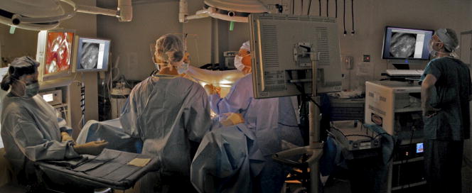 The microlaparoscope provides live images of excited fluorescence at 30 frames per second with an optical resolution of laterally and axially. The system frame rate is fundamentally limited by the acquisition rate of the CCD camera used for detection. Fluorescent contrast agents are delivered locally to the field of view using an integrated contrast agent delivery system. Using controls on the microlaparoscope, the surgeon can adjust focus from the nominal epithelial position down to an optical limit of below the surface. Table 1 provides a detailed listing of the system’s specifications. Table 1System specifications.
The evolution from a laboratory system26, 28, 29, 30 to a successful surgical system entailed significant translational research over a four-year period.32, 33, 34, 35 The work can be broken into two major areas: (1) the development of a mobile cart with a miniaturized confocal scan assembly (the OSU) and surgical control system and (2) the development of the clinical microlaparoscope. Both areas presented major challenges. The mobile cart required a redesign of the OSU and a change of the laser excitation system from a water-cooled gas laser to a small air-cooled solid-state laser. Making the microlaparoscope easy to use entailed significant developments to tightly integrate the focus and dye delivery systems to ensure quick and reliable response. In addition, the device had to be sterilizable, fit inside standard surgical trocars, and be safe to use inside a patient. In the following sections, we describe the mobile cart, the associated systems that it houses, and the functions that it provides. Then we will discuss the evolution of the microlaparoscope, beginning with the early prototypes and ending with the state-of-the-art instrumentation currently being used in human clinical trials. Details concerning the integrated in-handle axial focus and contrast agent delivery systems are also presented. 2.1.Mobile CartThe mobile cart houses the OSU and the control systems. The instrumentation fits on a standard endoscopy cart that has a by footprint. Figure 2 depicts the components on the mobile cart. The top shelf houses the sterile microlaparoscope and the surgical supplies that are used during the imaging procedure. The microlaparoscope cable connects to the OSU located on the second shelf. The third and fourth shelves house the laser, function generator, and computer. The bottom shelf houses a medical-grade isolation transformer. The operator display and controls for collecting data during surgery are located on a platform at standing height. A second mobile display is placed next to the operative field for viewing nearby the surgeon. Fig. 2Mobile microlaparoscope system. The mobile cart (left) houses the optical scan unit (OSU), surgical supplies, laser source, control systems, computer, and operator controls. The microlaparoscope cable connects to the OSU. The secondary display (right) is placed next to the operative field for live in vivo imaging. 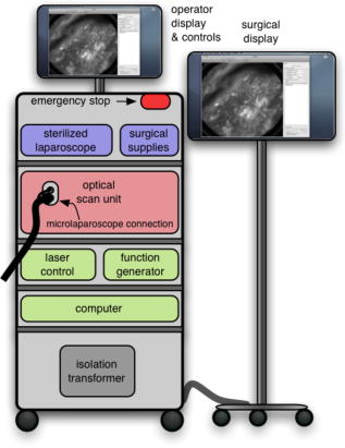 The system has been designed to streamline all operations during surgery. Once the system is plugged in and the safety interlocks engaged, the system starts, and all hardware is initialized. Hardware initialization includes the solid-state laser, camera, dye delivery system, focus system, and function generator for scan mirror control. After the automatic initialization, the operator is presented with the software control interface for live imaging. 2.1.1.Optical scan unitMiniaturization of the OSU required a redesign of the previous bench-top system. By simplifying the optical layout and integrating the multispectral imaging segment into a common collection path,36 we were able to fit the whole scan system into a by housing. The housing also integrates the scan mirror power supply and control electronics, which were external in the previous system. The components of the OSU are shown in Fig. 3 . The top of the figure shows how the system operates in the standard grayscale imaging mode. In this mode, a solid-state laser beam is expanded and anamorphically shaped into a line via a cylindrical lens. The laser light is then reflected into the image path by a dichroic filter, imaged to a line by a microscope objective, and scanned by the object scan mirror across the coherent fiber bundle face in the microlaparoscope’s proximal connector. Fig. 3Diagram of the OSU. The top portion illustrates the standard grayscale mode of operation. A laser is anamorphically shaped into a line and scanned onto the coherent fiber bundle in the microlaparoscope. The excited signal re-enters the system, is descanned, and is filtered through a confocal slit. The light is rescanned onto a two-dimensional 2-D CCD camera. In the spectral imaging mode (bottom inset), the image scan mirror is turned to its extreme position, redirecting the light through a dispersing prism.  Tissue fluorescence is collected back through the microlaparoscope and descanned by the object scan mirror. The dichroic filter passes the fluorescence signal, which is focused down onto a stationary confocal slit. The light exiting the slit is recollimated and rescanned using the image scan mirror. An emission filter removes residual excitation light. The beam is refocused back into a line that sweeps across the camera to build up a two-dimensional (2-D) image every thirtieth of a second. In addition to 2-D grayscale imaging, the system can also collect multispectral data.27, 29, 36 This multispectral mode is activated in a fraction of a second via a software actuation button that deflects the image scan mirror to its extreme position (shown in the bottom of Fig. 3). During spectral collection, the image scan mirror is held stationary. The light passes through a prism dispersing the signal across the CCD. The CCD camera records spectral information in the direction perpendicular to the slit and one dimension of spatial data in the dimension parallel to the slit. The second spatial dimension of the image is collected over time by recording multiple frames as the object scan mirror is slowly stepped. The complete spectral data collection procedure executes in a few seconds. Once spectral collection is complete, the system reverts back to real-time grayscale operating mode. 2.1.2.Software control systemA software package that interfaces with the data collection devices and the system controls was written using Objective C 2.0 and Cocoa with automatic garbage collection on Mac OS X. Figure 4 provides a general overview of the software and hardware interface. The software links the surgical controls on the microlaparoscope to the control systems that manage contrast agent delivery, focus, and data acquisition. Parallel processing allows the software to run smoothly while live images are acquired, processed, and encoded at 30 frames per second. A custom image processing memory pool class enables efficient resource management under automatic garbage collection. Fig. 4Flow diagram illustrating how the software integrates the hardware, live output, and data acquisition components of the microlaparoscope system. 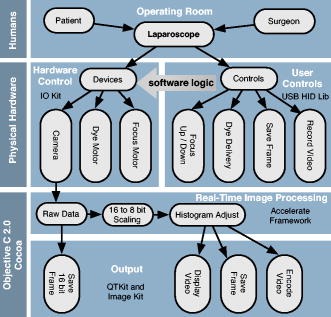 Figure 5 shows the software interface. It provides a simple interface for viewing and collecting live images during the surgical procedure. The software has controls to (1) start live acquisition, (2) save the current frame, (3) record video, (4) deliver dye, (5) load dye, and (6) adjust image display. In addition to the basic controls, the system also records procedure and patient information, which is archived with each image. System information, including image dynamic range and imaging depth, are also visible. During operation, the surgeon can easily see real-time imagery on the surgical display (shown in Fig. 1) along with the instrument’s current status. Contrast agent delivery, focus, and data acquisition can be initiated by the surgeon via integrated controls on the third-generation microlaparoscope handle, described in the next section. 2.2.Confocal MicrolaparoscopesUse of the surgical microlaparoscope entails placing the distal end in contact with the tissue, locally delivering fluorescent contrast agents to the field of view, adjusting focus, and collecting the resultant fluorescent confocal image. To create the surgical microlaparoscope, we had to develop (1) a reliable focus mechanism, (2) a localized contrast agent delivery system, and (3) an ergonomic sterilizable housing with surgical controls compatible with a -diam trocar instrument port. The development process encompassed three generations of instruments, with the final version meeting all of the requirements. Table 2 summarizes the key properties of the three designs. Table 2Comparison of key properties for the three generations of microlaparoscopes.
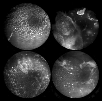
In all three designs, the microlaparoscope contains a 30,000-element fiber bundle connected via an subminiature version A (SMA) connector to the OSU. The OSU generates a line of laser illumination that sweeps across the proximal face of the fiber. The fiber bundle spatially relays the illumination pattern to the distal end of the fiber bundle, where a miniature objective lens30 images the illumination line to the desired tissue depth. Image depth is controlled by adjusting the axial spacing between the fiber bundle and the miniature objective lens. Contrast agent is locally delivered to the tissue through the microlaparoscope. The excited fluorescent signal is collected by the miniature lens and relayed back through the fiber bundle into the OSU. 2.2.1.First-generation designThe first-generation design—depicted in Fig. 6 —utilized a sterilizable semirigid -diam by -long dual-lumen polycarbonate sleeve through which a nonsterile imaging catheter was inserted.30 This simple design allowed us to rapidly move to clinical testing by creating a sterile housing for our existing flexible imaging catheter. The polycarbonate also integrated a small secondary lumen to deliver dye locally to the field of view. The front end of the polycarbonate sleeve was sealed with a -thick glass window. A -diam secondary lumen, used to deliver contrast agent, ran parallel to the primary lumen. A -diam hole in the window was placed over the secondary lumen, allowing contrast agent delivery to the tissue. Fig. 6First-generation microlaparoscope. The front end of the dual-lumen polycarbonate housing is shown on the right. The existing imaging catheter is inside the primary lumen, with the miniature objective flush against the glass window sealing the face. The secondary contrast agent fluid delivery lumen exits through a laser-drilled port in the glass face. The left side of the figure depicts the rear end of the polycarbonate housing passing into a trocar port. The dye line and imaging catheter are connected to the rear end of the housing. 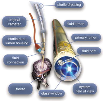 The rear end of the polycarbonate housing contained the couplings to mate the imaging catheter and the dye delivery line. In the operating room, the compression coupling of the sterilized polycarbonate housing was loosened, and the nonsterile imaging catheter was fed through the main lumen until the miniature objective was in contact with the glass window. The fitting was tightened, and then a sterile plastic cover was slid back over the portion of the imaging catheter that was in the operative field. A Luer Lock fitting coupled the fluid lumen to a medical-grade Teflon tubing that ran back to the mobile cart. The flexible catheter consisted of a miniature objective lens connected to durable polyetheretherketone (PEEK) tubing. The 30,000-element fiber optic bundle ran through the lumen of the PEEK tubing. Originally, focus was accomplished by a manual micrometer at the proximal end that moved the fiber bundle relative to the PEEK housing. However, focus control was unreliable due to an inexact fit of the fiber bundle inside the PEEK tubing. This resulted in hysteresis in the proximal movement of the fiber bundle relative to the fixed lens. Various methods were studied to improve the focus system.29, 30, 34 Ultimately, the manual focus micrometer was replaced by a computerized stepper motor. A hysteresis correction algorithm was developed to position the distal fiber face with an accuracy better than the system’s axial resolution. Figure 7 illustrates the ability of the first-generation focus system to image the epithelial surface of tissue (mouse peritoneal wall) and then to controllably focus the underlying tissue layers in increments. Fig. 7Image sequence demonstrating first-generation focus control and the confocal properties of the OSU. Sequence shows the process of incrementally focusing from the epithelial layer down to the muscle layer of mouse peritoneal wall in increments. (Circular field of view is .) 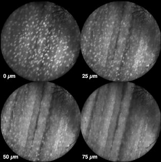 Dye delivery was accomplished by loading a syringe with fluorescent contrast agent. The syringe was then inserted into a syringe pump located on the mobile cart. The syringe was connected to the secondary lumen of the polycarbonate housing through -diam medical-grade Teflon tubing. Software control of the syringe pump enabled delivery of droplets of contrast agent onto the tissue surface near the field of view of the miniature objective. Figure 8 shows a photograph of the distal end of the microlaparoscope with a droplet of dye coming out through the hole in the glass window. Fig. 8Demonstration of contrast agent delivery in the first-generation system. Delivery time was approximately one second to deliver a volume. 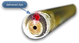 The device worked well using the -long imaging catheter. However, it was determined that a longer length imaging catheter was needed in the operating room. With the longer length catheter, the focus motor and the syringe pump were located far from the distal microlaparoscope tip, and focus would drift during use. Delivery of small droplets of contrast agent was unreliable. The surgeon also noted that positioning the proximal tip accurately was difficult because the polycarbonate housing was not rigid enough. 2.2.2.Second-generation designA second-generation device was developed to address the issues concerning device rigidity, focus drift, and reliability of contrast agent delivery across a -long connection between the microlaparoscope and the OSU. The second design abandoned the use of the existing flexible imaging catheter. To address the reliability issues of focus and dye delivery in a -long device, the controls for focus and dye delivery were located close to the distal tip. To address the rigidity issue, a rigid instrument was made using a stainless steel tube with an inner diameter matching the fiber bundle’s outer diameter. Figure 9 shows a diagram of the second-generation microlaparoscope. Fig. 9The second-generation microlaparoscope. The overall device, shown on the left, incorporated a manual focus mechanism and an integrated dye delivery system that uses a piezo valve and a pressurized syringe. The right side shows a cross-section of the depth/focus knob built into the handle. 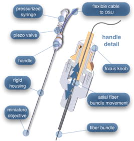 The miniature objective attached to the distal end of the -diam rigid stainless steel tube. The fiber bundle ran through the inside diameter of the rigid tube. To adjust focus, the fiber bundle moved axially relative to the fixed lens position. The tube and fiber bundle were held in place by a round handle containing a manual focus mechanism. Rotation of the handle knob resulted in precise movement of the proximal fiber face relative to the rigid tube. To deliver contrast agents, a 21-gauge hypodermic tube ran parallel to the rigid tube. Both tubes were sealed inside medical-grade fluorinated ethylene-propylene (FEP) heat-shrink tubing, resulting in a final outer diameter. At the distal tip, the hypodermic tube made a bend, dispensing contrast agents at the edge of the imaging field. At the back end of the handle, the hypodermic tubing passed into a computer controlled piezo valve immediately downstream from a pressurized syringe. A -long flexible cable ran from the handle to the OSU. The cable contained the fiber bundle and piezo valve electrical wires. The proximal end of the protective housing broke out into optical and electrical connectors. A standard SMA connector coupled the fiber bundle to the OSU. Compared to the first-generation system, the second-generation system was much easier to use because the whole microlaparoscope could be sterilized and then quickly connected to the OSU in the operating room. In contrast, the first-generation system required careful placement of the sterilized polycarbonate housing over the nonsterile imaging catheter permanently connected to the OSU. The rigid stainless steel tubing solved the rigidity issues, enabling the surgeon to precisely position the device. A press of a button at the operator console enabled rapid delivery of a small droplet of contrast agent, as shown in Fig. 10 . Focus was extremely reliable and never drifted. In fact, during typical use, the surgeon would set the focus at the epithelial surface and image multiple sites without needing to refocus. Fig. 10Demonstration of the ability of the second-generation microlaparoscope to deliver small volumes of contrast agent to the field of view. In this sequence of images, the operator presses the dye delivery button and the dye is delivered to the distal tip via actuation of the piezo valve. The delivered volume in this example is approximately .  Although the second-generation device addressed the primary issues encountered with the first-generation instrument, there were additional improvements that were important to make a successful clinical tool. Even though the manual focus system was reliable, a computerized system was desired to enable depth scans. Second, to allow the device to be controlled more efficiently by the surgeon, the microlaparoscope needed to integrate basic controls for focus, dye delivery, and data recording into the handle. The dye delivery system also needed some refinement. In the second-generation device, to ensure repeatable delivery of small contrast agent droplets, the pressure in the syringe had to be well regulated at a relatively high . This pressure would sometimes cause contrast agent to squirt out of the distal tip rather than pool up in a localized droplet. 2.2.3.Third-generation designTo implement these improvements, a third-generation device was developed. The new microlaparoscope, shown in Fig. 11, has an ergonomic handle, control buttons, a computerized focus system, and a refined contrast agent delivery system. Control of focus and dye delivery are consistent and reliable since the control systems were miniaturized and located in the handle only from the distal end of the device. A nonpressurized dye delivery system removed the problem encountered with dye ejection. Fig. 11The third-generation microlaparoscope. In this view, the rigid steel fiber bundle housing is visible entering into the main handle. A spring-loaded receptacle receives a syringe loaded with contrast agents, which couples into the fluid line running to the distal tip. Four buttons allow the surgeon to control focus, contrast agent delivery, and data acquisition. A -long flexible line connects the microlaparoscope back to the OSU.  Mechanically, the third-generation microlaparoscope followed the same design principles as the second-generation device. Figure 12 illustrates the mechanical aspects of the device. The fiber bundle couples to the focus motor inside the handle. A syringe with contrast agent is placed into a spring-loaded receiver at the front end of the handle. A second miniature motor in the handle acts as a plunger for the syringe. A spring forces the syringe to mate with a Luer Lock connection that guides the fluid down a 21-gauge hypodermic tube. Fig. 12Detailed cross-sectional view illustrating the focus mechanism and contrast agent delivery system in the third-generation microlaparoscope. The focus motor couples to the fiber bundle, causing axial movement of the distal end of the fiber relative to the lens. The motorized syringe plunger forces fluid in the syringe to pass through the fluid line, into the tip, and out the tiny orifice at the edge of the system’s field of view. (Diagram not to scale.) 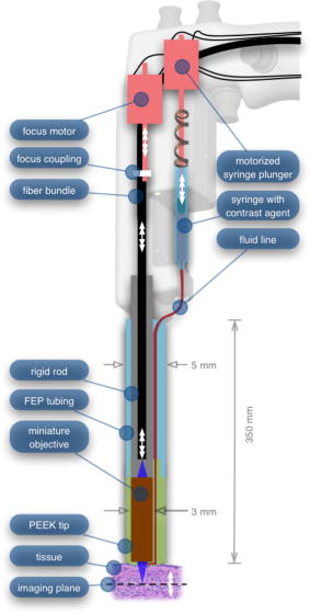 A customized tip helps to channel the dye and minimize tissue abrasion. The new tip is a PEEK housing mated to the FEP outer tubing. A tiny lumen inside the PEEK couples the hypodermic fluid line routing the dye to an exit port at the edge of the system’s field of view. In the second-generation design, the hypodermic tubing was bent around the tip of the miniature objective and had the potential to abrade the tissue surface. The new smooth tip helps to protect the tissue surface and allows the fluid exit port to be placed closer to the edge of the imaging field of view. The handle contains four ergonomically positioned controls. Two upper thumb controls on the back allow the surgeon to adjust focus and acquire a depth scan. The trigger button saves still frames with a short press and acquires video with a long press. The side button delivers a predefined amount of contrast agent to the field of view. The electrical wires and the fiber bundle are routed through the handle into a flexible protective cable. The rear end of the cable breaks out into an electrical connector and an SMA connector. Both connections couple to receptacles on the OSU. The electrical connection routes through the electronics of the OSU and exits as a single USB cable connecting to the computer which link the buttons and motors to the control software. The SMA connector couples the fiber bundle to the OSU. The third-generation microlaparoscope represents a viable surgical tool. Its rigid probe enables precise positioning control. The in-handle computerized focus system enables axial focus and depth scans with accurate positioning. The contrast agent system delivers volumes with precision down to . Last, the whole device has an ergonomic design that is comfortable for the surgeon to use and provides controls for all the tasks that the surgeon needs to perform. 3.ResultsAs previously mentioned, laparoscopic techniques can be used to access most organs in the body. To demonstrate the clinical viability of the confocal microlaparoscope system, we present results from two organs imaged using the device. The first set of results are in vivo and ex vivo images of the epithelial surface of ovarian tissue. Since there is no reliable way to detect ovarian cancer in its early stages,37 the microlaparoscope could be used to detect ovarian cancer in high-risk women. The second set of results are ex vivo images of human esophagus. Although laparoscopic esophageal surgery is a recent innovation, it is now second only to biliary tract surgery in the frequency of minimally invasive procedures performed in everyday surgical practice.38 The microlaparoscope’s ability to visualize the cellular boundaries of tumors could improve the success rates in laparoscopic staging of carcinoma of the esophagus and laparoscopic esophogectomy. 3.1.Ovarian ImagesCurrently, the microlaparoscope is being evaluated in a clinical trial to image the epithelial surface of the ovary at the University of Arizona’s Medical Center in Tucson. The device was granted “nonsignificant risk” status by the University of Arizona’s Institutional Review Board and has been approved for use in humans using a protocol that includes topical application of contrast agents.33 To date, 21 patients have been imaged in vivo. The current protocol entails imaging human ovaries in vivo before oophorectomy or hysterectomy. The imaging protocol begins with the surgeon locating the ovary and isolating it in an endobag with the ovary still connected to the blood supply (see Fig. 13 ). Once the ovary is isolated, the surgeon brings the tip of the microlaparoscope into contact with the epithelial surface. Then the surgeon delivers the contrast agent, and live imaging begins. The endobag protects the patient from inadvertent exposure to contrast agent. After the microscopic imaging is done, the surgical procedure is completed as normal, and the ovaries are removed. The removed ovary is typically imaged again ex vivo using the microlaparoscope with additional contrast agents. Biopsies are also taken for correlated pathology. Fig. 13Wide-field laparoscope view showing the second-generation microlaparoscope contacting the surface of the ovary. The organ, still attached to the blood supply, is laid inside an endobag to protect the patient from inadvertent exposure to contrast agents. 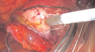 For the initial in vivo clinical studies, fluorescein sodium was selected because of its existing track record of safe use in humans.39, 40 (All patients participating in the clinical trials were consented and imaged in accordance with human subjects protocols approved by the Institutional Review Board of the University of Arizona.) Although fluorescein provides limited diagnostic contrast when applied to the surface of the ovary, it is a safe contrast agent and allowed us to test the safety and basic functionality of the microlaparoscope system in vivo. Figure 14 shows nine examples of in vivo images obtained with the microlaparoscope system. The images demonstrate that the device functions as designed. The microlaparoscope can deliver controlled volumes of dye to the image site and then display real-time cellular-level images to the surgeon. The focus mechanism works well. After an initial adjustment of the focus, the instrument can be moved to various sites on the ovary while still maintaining good focus on the epithelial surface. Fig. 14Images of ovary epithelium obtained in vivo during clinical trials using fluorescein sodium. The low contrast is a result of the minimal preferential binding exhibited by fluorescein. (Circular field of view is .) 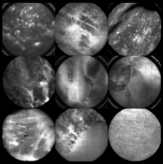 After in vivo imaging with fluorescein, the surgeon removes the ovaries. The ovaries are reimaged ex vivo using acridine orange (AO). Compared to fluorescein, AO provides superior diagnostic contrast. Example images with AO, shown in Fig. 15, demonstrate the excellent cellular-level contrast achievable with the instrument. The epithelial surface of a healthy ovary is characterized by a homogeneous distribution of bright nuclei, as seen in Fig. 15a. The epithelial surface cells of the ovary are delicate, and partial denuding can occur, exposing the underlying stroma [Fig. 15b]. Below the epithelial surface, healthy stroma also exhibits a characteristically homogenous structure albeit with a different nuclear size distribution and shape [Fig. 15c]. In the case of ovarian cancer, the tissue structure is visibly different [Fig. 15d]. The epithelial surface is irregular, and the high degree of heterogeneity in the size and spatial distribution of nuclei is indicative of ovarian cancer. Fig. 15Images of human ovary epithelium obtained ex vivo using AO. Subcaptions contain pathology diagnosis. (Circular field of view is .)  We have previously shown41 that the microlaparoscope system can easily differentiate between normal epithelium and ovarian cancer using automated algorithms. It also appears that the microlaparoscope system may be able to visualize cellular changes that happen prior to the onset of cancer. Less distinct tissue changes such as tissue sclerosis may also be detectable [Figs. 15e and 15f]. With the success of our initial testing with fluorescein, we have now begun imaging in vivo with AO. (Approval from the FDA to use AO in this context has been granted under IND 102603.) Figure 16 shows our preliminary results. These images depict the same homogeneous structure of nuclei as seen in Figs. 15a and 15b. Denuding of the delicate epithelium is also visible in some of the images. By optimizing the concentration of AO and giving surgeons more time to practice using the device, we believe we will achieve results comparable to the images obtained ex vivo. 3.2.Esophagus ImagesWe have conducted ex vivo imaging of esophagus tissue biopsies from more than 30 patients. Figure 17a shows an example of normal squamous epithelium. Figure 17b shows epithelial tissue that closely resembles the intestine, with columnar-appearing mucosa and intestinal metaplasia, a condition known as Barrett’s esophagus. Finally, Fig. 17c illustrates a tumor in the esophagus. Fig. 17Images of human esophagus epithelium obtained ex vivo using AO. Subcaptions contain pathology diagnosis. (Circular field of view is .)  These images illustrate the device’s ability to resolve the cellular details of tissue in the esophagus. Nuclear distributions are easily characterized, and morphological tissue changes can be readily discerned. In the case of laparoscopic esophogectomy, the microlaparoscope would allow the surgeon to optically biopsy suspect tissues to potentially find locations containing cancer. 4.Conclusions and Future WorkA mobile confocal microlaparoscope system capable of performing live optical biopsies in vivo has been developed. The system is currently being evaluated in clinical trials to assess its safety and efficacy for detecting ovarian cancer. Results show that the instrument is safe and can successfully image ovaries in vivo. The in vivo and ex vivo results indicate that the microlaparoscope can resolve sufficient cellular detail to detect the transformation of normal epithelium and visualize cellular changes that happen with the onset of cancer. As we continue testing, we hope to show that the device can obtain the same high-quality images in vivo as have been obtained ex vivo. Because the microlaparoscope can nondestructively provide real-time cellular images in vivo, it has the potential to significantly improve the rate of early cancer detection in laparoscopically accessible organs. Today, early detection of cancer is highly dependent on the selection of biopsy sites. Since biopsies are destructive, only a few are typically taken. If cancer is in its early stages, it will often be small, reducing the probability that it will be biopsied. Moreover, it takes time to get the biopsies processed and evaluated. However, because the microlaparoscope nondestructively acquires optical biopsies instantly, a much larger region of tissue can be interrogated at the cellular level. Additionally, if the surgeon finds a small cancer, the microlaparoscope could be used to locate the cancer boundaries allowing for immediate resection. Thus, the device might improve the probability of early cancer detection and help the surgeon fully resect the tumor during the same procedure. In the future, we will continue to investigate the wide range of potential applications for the confocal microlaparoscope system. Since the microlaparoscope is based on an inherently flexible fiber bundle, we plan on making a device with a flexible probe. We have previously shown a flexible imaging catheter and plan to apply the technology developed for the microlaparoscope to a new confocal microgastroscope for interrogating the gastrointestinal tract. AcknowledmentsThe authors wish to acknowledge the contribution of Dr. Molly Brewer, Dr. Richard Sampliner, Kathy Schmidt, and the surgical staff at UMC. Dr. Brewer helped motivate the development of the instrument and gave guidance on how such an instrument would be used in a clinical setting. Dr. Sampliner provided human esophagus biopsies for the ex vivo imaging studies. Kathy Schmidt and the surgical staff provided valuable assistance in the clinical trials. Last, we recognize the National Institutes of Health and the Arizona Disease Control Research Commission for their funding support provided through the following grants: NIH CA 73095, NIH CA 115780, and ADCRC 9711. ReferencesL. J. Kleinsmith, Principles of Cancer Biology,
(2006) http://www.loc.gov/catdir/toc/ecip0511/2005010378.html Google Scholar
T. Wang, M. Mandella, C. Contag, and G. Kino,
“Dual-axis confocal microscope for high-resolution in vivo imaging,”
Opt. Lett., 28 414
–416
(2003). https://doi.org/10.1364/OL.28.000414 0146-9592 Google Scholar
R. Kiesslich, L. Gossner, M. Goetz, A. Dahlmann, M. Vieth, M. Stolte, A. Hoffman, M. Jung, B. Nafe, P. Galle, and M. F. Neurath,
“In vivo histology of Barrett's esophagus and associated neoplasia by confocal laser endomicroscopy,”
Nat. Clin. Pract. Gastroenterol. Hepatol., 4 979
–987
(2006). 1743-4378 Google Scholar
A. Polglase, W. McLaren, S. Skinner, R. Kiesslich, M. Neurath, and P. Delaney,
“A fluorescence confocal endomicroscope for in vivo microscopy of the upper- and the lower-GI tract,”
Gastrointest. Endosc., 62 686
–695
(2005). https://doi.org/10.1016/j.gie.2005.05.021 0016-5107 Google Scholar
C. Boudoux, S. Yun, W. Oh, W. White, N. Iftimia, M. Shishkov, B. Bouma, and G. Tearney,
“Rapid wavelength-swept spectrally encoded confocal microscopy,”
Opt. Express, 13 8214
–8221
(2005). https://doi.org/10.1364/OPEX.13.008214 1094-4087 Google Scholar
A. Gerger, S. Koller, T. Kern, C. Massone, K. Steiger, E. Richtig, H. Kerl, and J. Smolle,
“Diagnostic applicability of in vivo confocal laser scanning microscopy in melanocytic skin tumors,”
J. Invest. Dermatol., 124 493
–498
(2005). https://doi.org/10.1111/j.0022-202X.2004.23569.x 0022-202X Google Scholar
Y. Kakeji, S. Yamaguchi, D. Yoshida, K. Tanoue, M. Ueda, A. Masunari, T. Utsunomiya, M. Imamura, H. Honda, Y. Maehara, and M. Hashizume,
“Development and assessment of morphologic criteria for diagnosing gastric cancer using confocal endomicroscopy: an ex vivo and in vivo study,”
Endoscopy, 38 886
–890
(2006). https://doi.org/10.1055/s-2006-944735 0013-726X Google Scholar
N. Nguyen and R. Leong,
“Current application of confocal endomicroscopy in gastrointestinal disorders,”
J. Gastroenterol. Hepatol, 23 1483
–1491
(2008). https://doi.org/10.1111/j.1440-1746.2008.05469.x 0815-9319 Google Scholar
Y.-T. Guo, Y.-Q. Li, T. Yu, T.-G. Zhang, J.-N. Zhang, H. Liu, F.-G. Liu, X.-J. Xie, Q. Zhu, and Y.-A. Zhao,
“Diagnosis of gastric intestinal metaplasia with confocal laser endomicroscopy in vivo: a prospective study,”
Endoscopy, 40 547
–553
(2008). https://doi.org/10.1055/s-2007-995633 0013-726X Google Scholar
M. Nakao, S. Yoshida, S. Tanaka, Y. Takemura, S. Oka, M. Yoshihara, and K. Chayama,
“Optical biopsy of early gastroesophageal cancer by catheter-based reflectance-type laser-scanning confocal microscopy,”
J. Biomed. Opt., 13 054043
(2008). https://doi.org/10.1117/1.2983674 1083-3668 Google Scholar
K. Konig, A. Ehlers, I. Riemann, S. Schenkl, R. Buckle, and M. Kaatz,
“Clinical two-photon microendoscopy,”
Microsc. Res. Tech., 70 398
–402
(2007). https://doi.org/10.1002/jemt.20445 1059-910X Google Scholar
S. Zhuo, J. Chen, T. Luo, X. Jiang, S. Xie, and R. Chen,
“Two-layered multiphoton microscopic imaging of cervical tissue,”
Lasers Med. Sci., 24 359
–363
(2008). https://doi.org/10.1007/s10103–008–0570–2 0268-8921 Google Scholar
R. Richards-Kortum, N. Ramanujam, A. Mahadevan-Jansen, M. Follen, and U. Utzinger,
“Method for probabilistically classifying tissue in vitro and in vivo using fluorescence spectroscopy,”
(2007). Google Scholar
U. Utzinger and R. Richards-Kortum,
“Fiber optic probes for biomedical optical spectroscopy,”
J. Biomed. Opt., 8
(1), 121
–147
(2003). https://doi.org/10.1117/1.1528207 1083-3668 Google Scholar
A. S. Haka, K. E. Shafer-Peltier, M. Fitzmaurice, J. Crowe, R. R. Dasari, and M. S. Feld,
“Diagnosing breast cancer by using Raman spectroscopy,”
Proc. Natl. Acad. Sci. U.S.A., 102 12371
–12376
(2005). https://doi.org/10.1073/pnas.0501390102 0027-8424 Google Scholar
J. T. Motz, S. J. Gandhi, O. R. Scepanovic, A. S. Haka, J. R. Kramer, R. R. Dasari, and M. S. Feld,
“Real-time Roman system for in vivo disease diagnosis,”
J. Biomed. Opt., 10 031113
(2005). https://doi.org/10.1117/1.1920247 1083-3668 Google Scholar
J. A. Freeberg, J. L. Benedet, C. MacAulay, L. A. West, and M. Follen,
“The performance of fluorescence and reflectance spectroscopy for the in vivo diagnosis of cervical neoplasia; point probe versus multispectral approaches,”
Gynecol. Oncol., 107 S248
–S255
(2007). https://doi.org/10.1016/j.ygyno.2007.07.008 0090-8258 Google Scholar
P. Mayes, D. Dicker, Y. Liu, and W. El-Deiry,
“Noninvasive vascular imaging in fluorescent tumors using multispectral unmixing,”
BioTechniques, 45 459
–464
(2008). https://doi.org/10.2144/000112946 0736-6205 Google Scholar
A. Tumlinson, J. Barton, B. Považay, H. Sattman, A. Unterhuber, R. Leitgeb, and W. Drexler,
“Endoscope-tip interferometer for ultrahigh resolution frequency domain optical coherence tomography in mouse colon,”
Opt. Express, 14 1878
–1887
(2006). https://doi.org/10.1364/OE.14.001878 1094-4087 Google Scholar
G. Tearney, S. Boppart, B. Bouma, M. Brezinski, N. Weissman, J. Southern, and J. Fujimoto,
“Scanning single-mode fiber optic catheter-endoscope for optical coherence tomography,”
Opt. Lett., 21 543
–545
(1996). https://doi.org/10.1364/OL.21.000543 0146-9592 Google Scholar
P. Wilder-Smith, W.-G. Jung, M. Brenner, K. Osann, H. Beydoun, D. Messadi, and Z. Chen,
“In vivo optical coherence tomography for the diagnosis of oral malignancy,”
Lasers Surg. Med., 35 269
–275
(2004). https://doi.org/10.1002/lsm.20098 0196-8092 Google Scholar
Z. Wang, C. Lee, W. Waltzer, Z. Yuan, Z. Wu, H. Xie, and Y. Pan,
“Optical coherence tomography for noninvasive diagnosis of epithelial cancers,”
129132
(2006). Google Scholar
Y. Chen,
“Ultrahigh resolution optical coherence tomography of Barrett's esophagus: preliminary descriptive clinical study correlating images with histology,”
Endoscopy, 39 599
–605
(2007). https://doi.org/10.1055/s-2007-966648 0013-726X Google Scholar
S. Lam, B. Standish, C. Baldwin, A. McWilliams, J. leRiche, A. Gazdar, A. I. Vitkin, V. Yang, N. Ikeda, and C. MacAulay,
“In vivo optical coherence tomography imaging of preinvasive bronchial lesions,”
Clin. Cancer Res., 14 2006
–2011
(2008). https://doi.org/10.1158/1078-0432.CCR-07-4418 1078-0432 Google Scholar
P.-A. Testoni and B. Mangiavillano,
“Optical coherence tomography in detection of dysplasia and cancer of the gastrointestinal tract and bilio-pancreatic ductal system,”
World J. Gastroenterol., 14 6444
–6452
(2008). https://doi.org/10.3748/wjg.14.6444 1007-9327 Google Scholar
A. F. Gmitro and D. Aziz,
“Confocal microscopy through a fiber-optic imaging bundle,”
Opt. Lett., 18 565
–567
(1993). https://doi.org/10.1364/OL.18.000565 0146-9592 Google Scholar
H. Makhlouf, A. F. Gmitro, A. A. Tanbakuchi, J. A. Udovich, and A. R. Rouse,
“Multispectral confocal microendocope for in vivo and in situ imaging,”
J. Biomed. Opt., 13 044016
(2008). https://doi.org/10.1117/1.2950313 1083-3668 Google Scholar
Y. S. Sabharwal, A. R. Rouse, L. Donaldson, M. F. Hopkins, and A. F. Gmitro,
“Slit-scanning confocal microendoscope for high-resolution in vivo imaging,”
Appl. Opt., 38 7133
–7144
(1999). https://doi.org/10.1364/AO.38.007133 0003-6935 Google Scholar
A. R. Rouse and A. F. Gmitro,
“Multispectral imaging with a confocal microendoscope,”
Opt. Lett., 25 1708
–1710
(2000). https://doi.org/10.1364/OL.25.001708 0146-9592 Google Scholar
A. R. Rouse, A. Kano, J. A. Udovich, S. M. Kroto, and A. F. Gmitro,
“Design and demonstration of a miniature catheter for a confocal microendoscope,”
Appl. Opt., 43 5763
–5771
(2004). https://doi.org/10.1364/AO.43.005763 0003-6935 Google Scholar
Surgical Lapraroscopy, Lippincott Williams & Wilkins, Hagerstown, MD (1991). Google Scholar
A. Tanbakuchi, A. Rouse, K. Hatch, R. Sampliner, J. Udovich, and A. Gmitro,
“Clinical evaluation of a confocal microendoscope system for imaging the ovary,”
Proc. SPIE, 6851 685103
(2008). https://doi.org/10.1117/12.760679 0277-786X Google Scholar
J. A. Udovich, A. R. Rouse, A. Tanbakuchi, M. A. Brewer, R. Sampliner, and A. F. Gmitro,
“Confocal micro-endoscope for use in a clinical setting,”
Proc. SPIE, 6432 64320H
(2007). https://doi.org/10.1117/12.701798 0277-786X Google Scholar
A. A. Tanbakuchi, A. R. Rouse, J. A. Udovich, and A. F. Gmitro,
“Surgical imaging catheter for confocal microendoscopy with advanced contrast delivery and focus systems,”
Proc. SPIE, 6082 608202
(2006). https://doi.org/10.1117/12.644812 0277-786X Google Scholar
A. R. Rouse, A. A. Tanbakuchi, J. A. Udovich, and A. F. Gmitro,
“Design of an in vivo multi-spectral confocal microendoscope for clinical trials,”
Proc. SPIE, 6082 608205
(2006). https://doi.org/http://link.aip.org/link/?PSI/6082/608205/1 0277-786X Google Scholar
H. Makhlouf, A. A. Tanbakuchi, A. R. Rouse, and A. F. Gmitro,
“Design of multi-spectral channel for in vivo confocal microscopy,”
Proc. SPIE, 6432 643206
(2007). https://doi.org/http://link.aip.org/link/?PSI/6432/643206/1 0277-786X Google Scholar
B. S. Kramer, J. Gohagan, and P. C. Prorok,
“NIH consensus 1994: screening,”
Gynecol. Oncol., 55 S20
–S21
(1994). https://doi.org/10.1006/gyno.1994.1335 0090-8258 Google Scholar
D. Bowrey and J. Peters,
“Laparoscopic esophageal surgery,”
Surg. Clin. North Am., 80 1213
–1242
(2000). https://doi.org/10.1016/S0039-6109(05)70221-8 0039-6109 Google Scholar
K. Lange and L. Boyd,
“The use of fluorescein to determine the adequacy of the circulation,”
Med. Clin. North Am., 26 943
–952
(1942). 0025-7125 Google Scholar
M. Morykwas, H. Hills, and L. Argenta,
“The safety of intravenous fluorescein administration,”
Ann. Plast. Surg., 26 551
–553
(1991). https://doi.org/10.1097/00000637-199106000-00009 0148-7043 Google Scholar
S. Srivastava, J. Rodríguez, A. Rouse, M. Brewer, and A. Gmitro,
“Computer-aided identification of ovarian cancer in confocal microendoscope images,”
J. Biomed. Opt., 13 024021
(2008). https://doi.org/10.1117/1.2907167 1083-3668 Google Scholar
|
||||||||||||||||||||||||||||||||||||||||||||||||||||||||||||||||||||||||