|
|
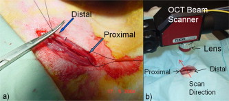
1.IntroductionChronic total occlusions (CTOs) are defined as arterial blockages that appear occluded under x-ray angiography and are older than .1 Patients that have a CTO are typically sent for coronary artery bypass (open heart) surgery instead of minimally invasive intravascular therapy such as angioplasty. The principal challenge of performing angioplasty for a CTO is the safe navigation of a guidewire through the dense collagen blockage without perforating the arterial wall.2, 3 While some experimental imaging guidance technologies have been suggested to differentiate between the blockage and the arterial wall.4 and hence guide this procedure, these methods are not generally available to interventional cardiologists. Despite their name, however, more than half of CTOs are actually less than 95% occluded under histological observation.5 Small channels are routinely observed in these lesions, and these channels may either remain within the lumen or exit the lesion, as shown schematically in Fig. 1 . Parallel studies with x-ray micro computed tomography have shown that these channels traverse a significant distance through the lesion, as shown in Fig. 1. We previously postulated that these channels may serve as useful conduits for a guidewire to follow through the occluded lumen6 as they may represent the path of least resistance through the occlusion. However, it has also been observed in histology that these channels occasionally exit from the lumen,5 potentially representing dangerous points where it would be easier to rupture the arterial wall. These channels are typically too small5 to be visualized using x-ray angiography and therefore present an attractive imaging target for a high-resolution intravascular imaging technique. Fig. 1Microchannels in CTOs. (a) Drawing representing a CTO illustrates both a microchannel that traverses the lesion and one that exits through the arterial wall. (b) Parallel studies with x-ray microcomputed tomography of rabbit arterial occlusion illustrate that these occlusions do possess long channels (labeled as MC) through the lesion. The white arrow in (b) identifies the proximal entrance, while the black arrow shows the location of the distal end. (c) A 3-D OCT volumetric image of a segment of an arterial occlusion, where the arterial medial wall (M) was manually segmented as red and a traversing microchannel (MC) as yellow and (d) corresponding Movat-stained histology. (e) A Volumetric OCT image of an arterial occlusion in which a microchannel appears to exit through the arterial wall and (f) the corresponding Movat histology. (Color online only.)  Intravascular imaging using optical coherence tomography (OCT) has attracted a great deal of attention for diagnosing arterial plaques that are prone to rupture.7, 8, 9 In previous work, we demonstrated that a time-domain OCT system can identify different pathologies ex vivo that are observed in CTOs in the peripheral arteries.10 We also were able to expand on this work to include 3-D volumes of human ex vivo occluded artery segments acquired from peripheral limb amputations using a swept source OCT system. In Figs. 1 and 1 we show two examples of 3-D OCT images in which the arterial wall (tunica media) and microchannels were manually segmented based on their optical backscattering properties. In the first example [Fig. 1], we were able to identify a channel that appears to pass directly through the occlusion, while in the second, [Fig. 1], we observed a channel that appears to exit out of the media wall. The corresponding histology is shown in Figs. 1 and 1. While these ex vivo imaging results are encouraging, in vivo imaging identification of these microchannels based solely on differences in reflectivity of the occlusive collagen and the blood-filled microchannel may prove difficult as both blood and collagen have high backscattering properties. One additional contrast mechanism for identifying channels is the use of flow information. Flow may also better indicate continuous channels. Previous high-frequency ultrasound imaging work by Thind was able to identify flow in the microchannels of a pig femoral artery CTO model.11 We therefore sought to demonstrate the potential of Doppler OCT as a means of providing contrast in a forward-viewing imaging geometry. The Doppler signal is defined by where is the mean velocity of the pixel being imaged, is the index of refraction of the object being imaged, is the Doppler angle (the angle between the imaging beam and the direction of the moving object), is the center wavelength of the imaging light source, and is the resulting Doppler shift. Therefore, the imaging geometry in which the flow direction is either parallel or antiparallel ( , ) to the imaging direction represents an optimal sensitivity to the Doppler frequency shift.As a first step to evaluate the feasibility of Doppler OCT to detect flow in nearly occluded arteries, a surgically exposed occluded femoral artery was imaged from the surface with bulk optics in a -old rabbit model. We then present work using a previously developed forward-viewing OCT catheter to image flow in phantoms that mimic nearly occluded lesions. 2.Methods and Materials2.1.Occluded Artery ModelTo test Doppler OCT’s ability to detect in vivo flow within microchannels, we used a thrombotic occlusion model in the rabbit femoral artery that was previously described.12, 13 Briefly, this model involves surgically exposing and isolating a rabbit femoral artery, ligating the artery both distally and proximally, injecting approximately thrombin solution (200 international units/ml) at the proximal end of the artery and then removing the proximal ligature to allow blood to flow into the lesion and create a thrombus [as shown in Fig. 2 ]. After approximately , the wound was closed and left for . 2.2.Intravital OCT ImagingAfter , the wound was reopened and the artery was isolated. It was imaged using a Thorlabs OCT system (SL1325-P16, New Jersey, USA, center wavelength , bandwidth , and axial scan speed of ) equipped with a handheld scanner attached to a surgical arm. The scanner consisted of a pair of galvomirrors and a lens, which scanned and focused the sample arm beam of the OCT system, respectively. This scanner was positioned above the artery, as shown in Fig. 2, such that it imaged across the artery creating a cross-sectional image of the occluded vessel. 2.3.Forward-Viewing Optical ProbeFor flow phantom measurements (and eventual in vivo use), a forward-viewing scanning probe was constructed similar to that described previously.14 Briefly, the probe used a high-voltage, low-current electrode and a cantilever coupled to a ground electrode through a dissipative polymer to scan an optical fiber across a graded-index (GRIN) lens. For the experiments presented here, the probe was driven at with oil immersion, which enabled scanning at (or when both slopes of the triangular waveform are used for imaging). To effectively visualize the entire cross section of the occlusion a working distance GRIN lens was used. This probe was packaged in a -diam Teflon tube. A schematic of the probe layout is shown in Fig. 3 and photographs of the probe when stationary and in motion are shown in Figs. 3 and 3, respectively. 2.4.Fourier-Domain Mode-Locked OCT SystemThe forward-looking probe was connected to the sample arm of the OCT system, consisting of a custom-made swept-source OCT system based on a tunable laser with a center wavelength of and a repetition rate of . The laser employed15 the Fourier domain mode-locking technique to achieve a ranging depth of . For in vivo use, the longer ranging depth may provide a larger field of view, given the relatively small sector scan angles provided by the forward-viewing probe. For OCT structural imaging, this system was able to generate when the scanning probe was operated at . For Doppler signal processing, an ensemble length of 32 lines was used to generate the forward-looking Doppler images. 2.5.Flow-Phantom ConstructionTo create phantoms mimicking blunt occlusions with microchannels, a -inner-diam (ID), -outer-diam (OD) Teflon tube was placed inside a larger -ID, -OD polycarbonate tube such that the smaller tube extended significantly out from both ends of the larger tube. The tube was then filled with a mixture of powder and polydimethylsiloxane (PDMS) at a ratio of and allowed to set. After the PDMS had cured, one end of the tube assembly was cut with a scalpel to create a clean face, as shown in the Fig. 4 . This assembly was then inserted into a stretchable Tygon tube such that the Tygon tube fit snugly over the tube assembly to create a layered structure that allows for fluid to be injected at one end. Other types of structures that were also created, including an oval-shaped channel [Fig. 4] and a tapered entrance created using a pipette tip [Fig. 4]. Fig. 4Variety of phantoms that were created for imaging flow in the forward direction: (a) a cleaved end face of -ID, -OD tube embedded in titanium doixide/PDMS to mimic the appearance of a central channel within an arterial occlusion (a polycarbonate tube is used as a rigid mold), (b) an oval-shaped channel that is used to mimic the appearance of a narrowed lesion, and (c) a pipette tip placed inside the polycarbonate tube to mimic a lesion that gradually tapers to a small channel. Scale bars represent .  As a first step, the entire flow phantom and the distal tube were filled with saline to create an optically clear field of view. A 1% mixture of Intralipid and saline was then added to a syringe, and this syringe was attached to the distal end of the small Teflon tube. The syringe was placed in an infusion pump to simulate flow coming through the microchannel. The probe was then placed inside the phantom and the high-voltage power supply that was connected to the probe was activated so that the probe began to oscillate. The distance from the probe to the cleaved face of the flow phantom was adjusted such that the entire proximal end of the “occlusion” could be visualized. The setup for this work is detailed schematically in Fig. 5 . Fig. 5Setup used for forward-viewing Doppler OCT in which the electrostatic probe images flow directed toward it through a small-diameter Teflon tube. 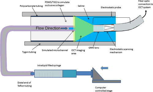 Once a clear view of the proximal end of the flow phantom was obtained, the infusion pump was activated at rate of . The data acquisition was initiated once the Intralipid was seen in the microchannel tube, several centimeters away from the imaging area. The purpose of this timing sequence was to capture the arriving bolus of Intralipid. 3.Results3.1.In Vivo DOCT ImagingTwo-week-old arterial occlusions in a rabbit were exposed surgically and imaged. The structural OCT image in Fig. 6 shows the artery as outlined by the red dotted line. Within the artery is what appears to be a microchannel, as identified by the arrow. The Doppler OCT image sequence [Figs. 6, 6, 6, 6, 6] demonstrates that the central microchannel does possess pulsatile flow. The Movat-stained histology slide shown in Fig. 6 also illustrates the central microchannel within the occluded lumen. Using an estimated Doppler angle of and the known properties of the swept-source laser, we estimated the peak velocity seen in this channel as approximately . Fig. 6Surgically exposed -old occlusion with both (a) structural and (b) to (f) a time sequence of Doppler images separated by . The Doppler image identifies a central microchannel. A red dotted curve is used to identify the outer border of the artery on the structural image in (a). A representative Movat-stained histology slide is shown in (g). The adventitia is labeled Ad and the media is labeled M. Blue arrows identify the central microchannel in both the structural OCT (a) and histology images (g). Scale bars represent . (Color online only.)  3.2.Forward-Viewing Catheter Doppler OCT ImagingA time sequence of structural OCT images displaying the arrival of a bolus of Intralipid in the phantom is shown in Figs. 7, 7, 7 , with the corresponding forward-looking Doppler OCT (DOTC) images shown in Figs. 7, 7, 7. The flow profile, as seen in the DOCT images [Figs. 7, 7, 7] appears parabolic through the channel. The Doppler images displayed aliased flow, as seen by the transition from yellow to blue (representing a transition in phase shift from negative to positive ). In this situation, the phase difference between the adjacent lines is greater than . However, the measurement range for phase is limited from to , corresponding to . Thus, phase differences greater than this range will jump between and . Fig. 7Sequence of images taken every showing both the structural (a) to (c) and (d) to (f) the corresponding Doppler progression of a bolus of Intralipid through a microchannel in an occlusion phantom. The occluded lumen composed of PDMS and is identified in (a) as OL. The TygonTM tubing walls are seen as dark borders on either side of each image and are labeled with a W. Red arrowheads identify the outer walls of the embedded tube used to form the microchannel in (a). Scale bars represent . (Color online only.) 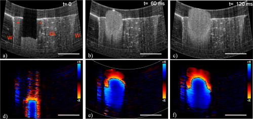 We were also able to examine several other geometries of the CTO phantoms, including imaging flow through a tapered entrance, as shown in Fig. 8 , and the oval-shaped microchannel, as shown in Fig. 9 . In both cases, the Doppler images serve to provide additional contrast over the structural images. This contrast is important in situations where the surrounding occlusion and the microchannel fluid have similar scattering properties, such as with collagen and blood. Fig. 8(a) Schematic drawing of flow from a tapered exit occlusion directed toward the forward-viewing electrostatic probe (the red arrow indicates the direction of flow), and (b) structural and (c) Doppler images of Intralipid flow arriving in a tapered phantom [as shown in Fig. 4] are displayed. Scale bars in (b) and (c) represent .(Color online only.)  Fig. 9Imaging flow through an oval channel using a forward-viewing Doppler OCT probe: (a) the orientation of the probe with respect to the flow phantom [as shown in Fig. 4], (b) the face-on schematic of the flow phantom and the orientation of the imaging slice through it, (c) the structural image of Intralipid arriving through the channel, and (d) the corresponding Doppler image. Scale bars in (c) and (d) represent . 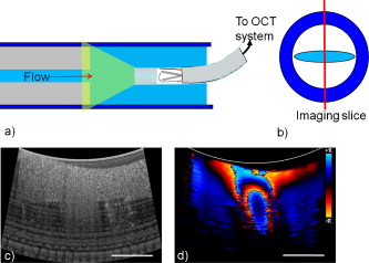 4.DiscussionAdvanced real-time imaging techniques in interventional cardiology capable of guiding procedures in arteries that appear occluded under x-ray angiography remain a highly desired but unrealized goal. Success rates for opening such arteries, in both the peripheral and coronary circulation, are much lower than for stenotic but not fully occluded lesions,16 in large part due to inadequate visualization of the occluded segment. This preliminary study demonstrates that Doppler OCT can image flow in the small channels that recanalize an arterial occlusion. The calculated flow velocity in the channel detected in a -old occlusion is similar in value to the Doppler ultrasound results in microchannels of a pig femoral arterial occlusion.11 This study also demonstrates Doppler imaging in flow phantoms with a forward-viewing catheter in which the imaging direction and the flow direction were nearly antiparallel. The Doppler images provide an added contrast mechanism that may help to identify small channels and the geometry of the lumen. This information in turn may help to define the overall morphology of the occlusion as well as identify points where the channels exit the occlusion. This study was limited in its intravascular application to the imaging of an arriving bolus of Intralipid in flow phantoms. This limitation was a result of the small angular field of view of the probe and the requirement of imaging an entire cross section of the flow phantom. Reconciling these two points required the use of a longer working distance lens in the probe. However, because of the limited imaging penetration of OCT through Intralipid, this long working distance made imaging cases of constant Intralipid flow severely restricted. Thus, we were only able to study cases in which flow was directed toward the imaging catheter. In an in vivo implementation, flow would likely be directed away from the catheter either by pulsatile blood flow or through the injection of a blood and saline mixture to obtain an optimal balance of backscattered signal and imaging depth. In such an imaging geometry, it is likely that the probe itself will alter the flow pattern. Investigation of these effects remains a subject of ongoing endeavors. Practical in vivo implementation requires several important improvements to the current probe design. Increasing the angular field of view is necessary to enable the probe to be placed closer to the proximal end of the occlusion while maintaining a full visualization of both the blockage and the two sides of the arterial wall. Furthermore, to generate 3-D forward-looking images analogous to those shown in Figs. 1 and 1 in vivo, image acquisition time would need to be improved by a factor of 20. Possible methods to implement such an increase include moving toward a fiber bundle/array design17 or a fast-scanning piezoelectric oscillator design.18 The probe’s dimensions also require considerable miniaturization to be used effectively in vivo. The probe used in this work had a diameter of with a rigid length of . For use in a clinically relevant imaging scenario in interventional cardiology, a diameter of with a rigid length of less than would be required. To address this miniaturization issue, we are currently investigating methods of incorporating planar electrodes directly into the catheter’s outer sheath as well as investigating fiber array designs, which may be more amenable to miniaturization. Development of an effective means to clear the blood field to enable for imaging of the proximal end of the occlusion will also require careful thought. Possible methods include the incorporation of a balloon onto the imaging catheter or the use of saline flushing ports directly incorporated onto the outer sheath of the catheter. Theoretically the relatively small blood flow volume through the microchannel(s) in CTO lesions may reduce the difficulty of saline flush compared to conventional coronary OCT imaging requirements. Integrating therapeutic means with a forward-looking OCT catheter will also be necessary for this technology to be adopted in a clinical environment. Incorporating laser ablation techniques via optical fibers embedded within the outer sheath of the imaging catheter is a particularly attractive solution as it may enable simultaneously imaging and ablating the blockage. The use of ultrafast laser ablation may also be advantageous, as this method would enable the removal of calcified tissue.19 Despite these challenges, the ability to image the proximal end of the occlusion and to identify the geometry of severely narrowed arterial lesions using Doppler OCT would provide a valuable tool for interventional cardiology. The potential application using Doppler OCT data to guide wires through the lesion and to identify points where channels exit the vessel could make interventions on occluded arteries safer, more successful, and less invasive. AcknowledgmentsThis work was supported by the Canadian Institutes of Health Research (Grant No. CTP82943), the Canadian Foundation for Innovation, and the Ontario Centres of Excellence. ReferencesG. W. Stone,
D. E. Kandzari,
R. Mehran,
A. Colombo,
R. S. Schwartz,
S. Bailey,
I. Moussa,
P. S. Teirstein,
G. Dangas,
D. S. Baim,
M. Selmon,
B. H. Strauss,
H. Tamai,
T. Suzuki,
K. Mitsudo,
O. Katoh,
D. A. Cox,
A. Hoye,
G. S. Mintz,
E. Grube,
L. A. Cannon,
N. J. Reifart,
M. Reisman,
A. Abizaid,
J. W. Moses,
M. B. Leon, and
P. W. Serruys,
“Percutaneous recanalization of chronically occluded coronary arteries: a consensus document: part I,”
Circulation, 112
(15), 2364
–2372
(2005). https://doi.org/10.1161/CIRCULATIONAHA.104.481283 0009-7322 Google Scholar
J. A. Puma,
M. H. Sketch Jr., J. E. Tcheng,
R. A. Harrington,
H. R. Phillips,
R. S. Stack, and
R. M. Califf,
“Percutaneous revascularization of chronic coronary occlusions: an overview,”
J. Am. Coll. Cardiol., 26
(1), 1
–11
(1995). https://doi.org/10.1016/0735-1097(95)00156-T 0735-1097 Google Scholar
T. Noguchi,
M. S. Miyazaki,
I. Morii,
S. Daikoku,
Y. Goto, and
H. Nonogi,
“Percutaneous transluminal coronary angioplasty of chronic total occlusions. Determinants of primary success and long-term clinical outcome,”
Cath. Cardiovasc. Interv., 49
(3), 258
–264
(2000). https://doi.org/10.1002/(SICI)1522-726X(200003)49:3<258::AID-CCD7>3.0.CO;2-L Google Scholar
B. K. Courtney,
N. R. Munce,
K. J. Anderson,
A. S. Thind,
G. Leung,
P. E. Radau,
F. S. Foster,
I. A. Vitkin,
R. S. Schwartz,
A. J. Dick,
G. A. Wright, and
B. H. Strauss,
“Innovations in imaging for chronic total occlusions: a glimpse into the future of angiography’s blind-spot,”
Eur. Heart J., 29
(5), 583
–593
(2008). https://doi.org/10.1093/eurheartj/ehm634 0195-668X Google Scholar
S. S. Srivatsa,
W. D. Edwards,
C. M. Boos,
D. E. Grill,
G. M. Sangiorgi,
K. N. Garratt,
R. S. Schwartz, and
D. R. Holmes Jr.,
“Histologic correlates of angiographic chronic total coronary artery occlusions: influence of occlusion duration on neovascular channel patterns and intimal plaque composition,”
J. Am. Coll. Cardiol., 29
(5), 955
–963
(1997). https://doi.org/10.1016/S0735-1097(97)00035-1 0735-1097 Google Scholar
B. H. Strauss,
A. Segev,
G. A. Wright,
B. Qiang,
N. Munce,
K. J. Anderson,
G. Leung,
A. J. Dick,
R. Virmani, and
J. Butany,
“Microvessels in chronic total occlusions: pathways for successful guidewire crossing,”
J. Interv. Cardiol., 18
(6), 425
–436
(2005). https://doi.org/10.1111/j.1540-8183.2005.00082.x 0896-4327 Google Scholar
J. G. Fujimoto,
S. A. Boppart,
G. J. Tearney,
B. E. Bouma,
C. Pitris, and
M. E. Brezinski,
“High resolution in vivo intra-arterial imaging with optical coherence tomography,”
Heart, 82
(2), 128
–133
(1999). 1355-6037 Google Scholar
I. K. Jang,
G. J. Tearney,
B. MacNeill,
M. Takano,
F. Moselewski,
N. Iftima,
M. Shishkov,
S. Houser,
H. T. Aretz,
E. F. Halpern, and
B. E. Bouma,
“In vivo characterization of coronary atherosclerotic plaque by use of optical coherence tomography,”
Circulation, 111
(12), 1551
–1555
(2005). https://doi.org/10.1161/01.CIR.0000159354.43778.69 0009-7322 Google Scholar
S. H. Yun,
G. J. Tearney,
B. J. Vakoc,
M. Shishkov,
W. Y. Oh,
A. E. Desjardins,
M. J. Suter,
R. C. Chan,
J. A. Evans,
I. K. Jang,
N. S. Nishioka,
J. F. de Boer, and
B. E. Bouma,
“Comprehensive volumetric optical microscopy in vivo,”
Nat. Med., 12
(12), 1429
–1433
(2006). https://doi.org/10.1038/nm1450 1078-8956 Google Scholar
N. R. Munce,
V. X. Yang,
B. A. Standish,
B. Qiang,
J. Butany,
B. K. Courtney,
J. J. Graham,
A. J. Dick,
B. H. Strauss,
G. A. Wright, and
I. A. Vitkin,
“Ex vivo imaging of chronic total occlusions using forward-looking optical coherence tomography,”
Lasers Surg. Med., 39
(1), 28
–35
(2007). https://doi.org/10.1002/lsm.20449 0196-8092 Google Scholar
A. S. Thind,
G. Leung,
N. R. Munce,
J. J. Graham,
K. J. Anderson,
A. J. Dick,
B. H. Strauss,
G. A. Wright, and
F. S. Foster,
“Investigation of micro-ultrasound for microvessel imaging in a model of chronic total occlusion,”
Ultrason. Imaging, 29
(3), 167
–181
(2007). 0161-7346 Google Scholar
B. H. Strauss,
L. Goldman,
B. Qiang,
N. Nili,
A. Segev,
J. Butany,
J. D. Sparkes,
Z. S. Jackson,
M. R. Eskandarian, and
R. Virmani,
“Collagenase plaque digestion for facilitating guide wire crossing in chronic total occlusions,”
Circulation, 108
(10), 1259
–1262
(2003). https://doi.org/10.1161/01.CIR.0000086320.24172.A1 0009-7322 Google Scholar
R. Jaffe,
G. Leung,
N. R. Munce,
A. S. Thind,
H. Leong-Poi,
K. J. Anderson,
X. Qi,
J. Trogadis,
A. Nadler,
D. Shiff,
J. Saperia,
J. Lockwood,
C. Jacobs,
B. Qiang,
A. Teitelbaum,
A. J. Dick,
J. D. Sparkes,
J. Butany,
G. A. Wright, and
B. H. Strauss,
“Natural history of experimental arterial chronic total occlusions,”
J. Am. Coll. Cardiol., 53
(13), 1148
–1158
(2009). https://doi.org/10.1016/j.jacc.2008.09.064 0735-1097 Google Scholar
N. R. Munce,
A. Mariampillai,
B. A. Standish,
M. Pop,
K. J. Anderson,
G. Y. Liu,
T. Luk,
B. K. Courtney,
G. A. Wright,
I. A. Vitkin, and
V. X. Yang,
“Electrostatic forward-viewing scanning probe for Doppler optical coherence tomography using a dissipative polymer catheter,”
Opt. Lett., 33
(7), 657
–659
(2008). https://doi.org/10.1364/OL.33.000657 0146-9592 Google Scholar
G. Y. Liu,
A. Mariampillai,
B. A. Standish,
N. R. Munce,
X. Gu, and
I. A. Vitkin,
“High power wavelength linearly swept mode locked fiber laser for OCT imaging,”
Opt. Express, 16
(18), 14095
–14105
(2008). https://doi.org/10.1364/OE.16.014095 1094-4087 Google Scholar
R. D. Safian,
C. H. McCabe,
M. E. Sipperly,
R. G. McKay, and
D. S. Baim,
“Initial success and long-term follow-up of percutaneous transluminal coronary angioplasty in chronic total occlusions versus conventional stenoses,”
Am. J. Cardiol., 61
(14), 23G
–28G
(1988). https://doi.org/10.1016/S0002-9149(88)80028-6 0002-9149 Google Scholar
Y. Luo,
L. J. Arauz,
J. E. Castillo,
J. K. Barton, and
R. K. Kostuk,
“Parallel optical coherence tomography system,”
Appl. Opt., 46
(34), 8291
–8297
(2007). https://doi.org/10.1364/AO.46.008291 0003-6935 Google Scholar
X. Liu,
M. J. Cobb,
Y. Chen,
M. B. Kimmey, and
X. Li,
“Rapid-scanning forward-imaging miniature endoscope for real-time optical coherence tomography,”
Opt. Lett., 29
(15), 1763
–1765
(2004). https://doi.org/10.1364/OL.29.001763 0146-9592 Google Scholar
B. Girard,
D. Yu,
M. R. Armstrong,
B. C. Wilson,
C. M. Clokie, and
R. J. Miller,
“Effects of femtosecond laser irradiation on osseous tissues,”
Lasers Surg. Med., 39
(3), 273
–285
(2007). https://doi.org/10.1002/lsm.20466 0196-8092 Google Scholar
|