|
|
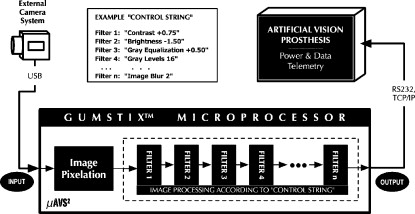
1.IntroductionSystems providing artificial vision are becoming a reality.1, 2, 3, 4, 5, 6, 7, 8, 9, 10, 11, 12, 13, 14, 15, 16, 17, 18, 19, 20, 21, 22, 23 In particular, (extraocular or intraocular) camera-driven epiretinal implants are being used in chronic patient trials already6, 5 (Fig. 1 ). With blind subjects, it is difficult to predict exactly what they can perceive with such camera-driven visual prostheses, especially since they (currently) provide only tens of stimulating retinal electrodes, thereby allowing only for limited visual perception (pixelation). Thus it is important to offer them a wide variety of image processing filters and the capability to engage these filters repeatedly in any user-defined order to enhance their visual perception in daily life. Fig. 1One instantiation of an artificial vision prosthesis: an intraocular retinal prosthesis using an external microelectronic system to capture and process image data and transmit the information to an implanted microelectronic system. The implanted system decodes the data and stimulates the retina via an electrode array with a pattern of electrical impulses to generate a visual perception.  Image processing systems (Fig. 2 ), such as the artificial vision simulator (AVS)24, 25, 26 (Fig. 3 ), provide these capabilities and perform real-time (i.e., ) image processing and enhancement of digital camera image streams before they enter the visual prosthesis. AVS, in particular, comprises numerous efficient image manipulation and processing modules, such as user-defined pixelation, contrast and brightness enhancement, grayscale equalization for luminance control under severe contrast and brightness conditions, user-defined grayscale levels for potential reduction of data volume transmitted to the visual prosthesis, blur algorithms, and edge detection.27, 28 AVS provides the unique ability and flexibility for visual prosthesis carriers to further customize their individual visual perception afforded by their respective vision systems by actively manipulating parameters of individual image processing filters, even altering the sequence of these filters. Fig. 2Schematic diagram of a real-time image processing system for artificial vision prostheses, which are driven by an external or internal camera system.  Fig. 3(Top) Typical palette of image processing modules that can be applied in real time to a video camera stream driving an artificial visual prosthesis. (Bottom) a user-defined subset of filters (pixelation plus grayscale equalization plus contrast enhancement) applied in a real world scenario: recognizing a door and doorknob in a low contrast environment. 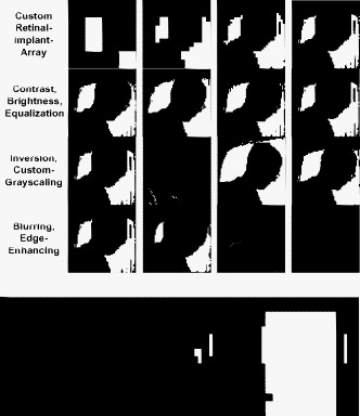 The original implementation of the AVS processing system has been laptop computer based and hence not truly portable. To provide independent mobility for the blind and visually impaired using camera-driven artificial visual prostheses (Fig. 1), we introduce in the following a stand-alone, battery-powered, portable microcomputing platform and software system for real-time image processing for camera-driven artificial vision prostheses, the microcomputer-based artificial vision support system .29 2.Methods2.1.Hardware PlatformFor the purpose of creating a small, stand-alone, battery-operated, and portable version of AVS, namely , we employed a commercial off-the-shelf, battery-powered, general purpose miniaturized Linux processing platform: the Gumstix™ (by Gumstix, Incorporated, Portola Valley, California) microcomputer environment (Fig. 4 ). It is lightweight , fast ( clock speed or better), and equipped with USB, Ethernet, and RS-232 interfaces. Fig. 4Gumstix™-based , a stand-alone, battery-operated, portable, general purpose microcomputing platform for real-time image processing.  In particular, the Verdex-Pro class Gumstix microcomputer has the following specifications (see http://www.gumstix.net/Hardware/view/Hardware-Specifications/Verdex-Pro-Specifications/112.html): 2.2.Microcomputer-Based Artificial Vision Support System Processing ArchitectureFor visual processing purposes, imports raw video frames from a camera connected via its built-in USB port (or alternatively via its built-in Ethernet port, see Fig. 5 ). then reduces the resolution of the video frames to match the pixel resolution of the patient’s visual prosthesis (i.e., pixelation or downsampling, see Fig. 5). subsequently processes the downsampled video frames through user-selected image filters in a linear, sequential-loop fashion, resulting in vastly reduced memory and CPU requirements during execution, making the use of a microprocessor possible. The frequency and order of the image processing modules are determined via a predefined, user-selectable “control string” or script without recompilation of the image processing code (Fig. 5). then issues the processed video frame data over an outbound connection (via RS-232, wired Ethernet, or Internet) to the visual prosthesis system in real time (Fig. 5). The control string or script defines the order and frequency that the image filters are applied to the input video frames. Each image filter in a specific sequence is applied to the results of the filter before it, in a net cascading effect. Thus, filter 1 is applied to the raw pixelated video frame; filter 2 is then applied to that result, and so on to the last filter, at which time the processed image is ready to be issued for stimulation of the prosthesis. This cycle repeats anew for each incoming video frame. Before use, the blind subject is tested and the specific sequence of filters that provides him the best results is determined. This sequence is incorporated into the control script, which is then downloaded onto the device. In the current implementation of , the control script is not changeable by the user; however, implementing on an advanced embedded platform such as an Apple iPhone could allow the user the selection of a number of prepared control scripts in real time (e.g., one for daytime, one for nighttime, etc.). In particular adheres to the following modular processing architecture (Fig. 5). Stage 1: camera image acquisitionutilizes access to an “image generator,” i.e., a digital video camera. The camera may be local, directly connected via the built-in USB port, or it may be a local or remote IP camera on an accessible network. For a locally connected (hardwired) camera, will open an exclusive read channel to the device over the USB bus to gain access to the camera’s video buffer. For an IP camera, will access the camera at its IP address, using the access protocol specific to the type of camera in use (e.g., HTTP, UDP). Stage 2: image captureOnce has established a connection to a digital video camera, it must extract discrete image frames from the camera. It does this by reading the camera’s YUV frame buffer. Stage 3: custom image processing including pixelationThe standardized image representation is reduced in resolution (pixelated) to match the pixel resolution of the patient’s retinal implant electrode array. For example, if the original image representation has a resolution of raw pixels, the image is downsampled to the patient’s electrode array size, e.g., , thus becoming a array. This downsampling affords its real time capability, as it allows for a subsequent dramatic speed-up of otherwise computationally expensive image processing filters that can now be equally efficiently executed on the reduced-size pixel array rather than the full-resolution camera video frames (for more detail see Sec. 2.4). Specialized image processing filters (e.g., contrast, brightness, gray equalization, gray levels, inversion, edge detection, and image blur27, 28) are then applied to the resolution-reduced/pixelated image (pixel array) according to a predefined/user-selectable control string or script to enhance its essential characteristics, cleaning up the image before issuance to the retinal implant. Stage 4: image data transmissionThe final stage in processing causes the processed pixel array to be sent to a power and data telemetry system (Fig. 5) that subsequently outputs the image data, e.g., by means of electrical current pulses on the patient’s retinal implant electrode array to generate visual perceptions, i.e., so-called phosphenes. 2.3.Microcomputer-Based Artificial Vision Support System Connectivitysupports a variety of interfaces that enable its connectivity to input devices such as digital cameras, and to output devices such as artificial vision systems. The interfaces currently supported are as follows. 2.3.1.Universal Serial Bus Camera Interfacecontains a fully supported, general purpose USB port, allowing for the connection of a wide range of USB devices, including many types of USB web cameras, without the need of an external power supply. Alternatively, accessing an IP camera is possible as well, using an HTTP protocol to an IP camera connected to the onboard Ethernet port. When using a YUV-capable USB or IP camera, the camera’s grayscale video frame buffer is directly accessible to the image processing filters. 2.3.2.Ethernet-Based (Transmission Control Protocol/Internet Protocol) Data Exchange ProtocolTo integrate the with artificial vision prostheses, an extensible Ethernet-based (i.e., TCP/IP) data exchange protocol (Fig. 6 ) has been developed (for details see Ref. 26) to facilitate the transfer of the -manipulated (video) output data to, e.g., power and data telemetry systems for retinal prostheses.30 This Ethernet-based protocol allows for maximum flexibility between systems, and is capable of two-way data transfer as well as status message transmission. The interface protocol is sufficiently flexible, so that it is also possible for a power and data telemetry system to transmit its own data (e.g., measurement data obtained from the vision implant) back to for feedback control, further processing, and analysis. Additionally, contingency measures are integrated into the protocol, providing for negative acknowledgements and data resend requests, should the need arise in which data is required to be resent. Fig. 6Schematic view of Ethernet-based data exchange protocol between and a power and data telemetry system of an artificial vision prosthesis.30 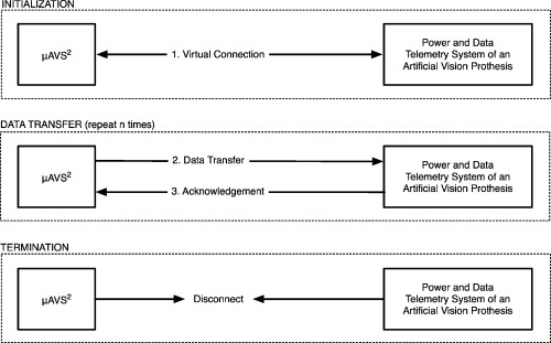 2.3.3.RS232 Communication ProtocolUsing the onboard universal asynchronous receiver/transmitter, it is possible to write the -manipulated (video) output data to the Gumstix serial port at speeds of up to 921,600 baud, using a RS-232 8N1 format: each data byte is actually nine bits long, i.e., eight data bits and one stop bit. 2.4.Microcomputer-Based Artificial Vision Support System Real-Time Image Processing CapabilityThe real-time image processing capability of is enabled by the downsampling of the native resolution of the artificial vision prosthesis camera system before image processing filters are applied. For example, if the original image representation has a resolution of raw pixels (i.e., ), and if the implanted electrode array of an epiretinal vision implant has a dimension of stimulating electrodes (i.e., 256 electrodes), then the downsampling/binning of the image to affords a speed-up factor of 1200 (i.e., 3 orders of magnitude) in subsequent filter processing. This process allows otherwise computationally expensive image processing filters (e.g., blurring) to be executed in real time (i.e., in excess of ) without loss of filter validity/efficiency. In the Appendix{ label needed for app[@id='x0'] } in Sec. 5 we show mathematically and numerically, for a set of relevant image processing filters, that downsampling first and subsequent filtering of the reduced size image yields the exact or nearly exact same end result (i.e., is commutable or nearly commutable) compared to downsampling after image processing filters have been applied to the full-resolution camera video frames. This speed-up enables the employment of computationally low power, portable, and battery-powered microcomputing platforms to perform real-time image processing within an artificial vision system, thereby affording users enhanced mobility and independence. 3.ResultsTable 1 demonstrates the binning/downsampling performance efficiency of for various artificial vision prostheses with electrode array dimensions ranging from to . For example, is capable of binning an in-memory source image (i.e., a frame) of down to at a rate of 354 frames per second (fps). Table 1Binning/downsampling performance efficiency of μAVS2 in frames per second for artificial vision prostheses with various electrode array dimensions and a camera frame resolution of 160×120pixels .
Table 2 shows individual and total filter performance efficiencies for various electrode array dimensions, obtained with an in-memory frame of . The results show that the application of filters to the workflow impact the processing only marginally. For example, adding a contrast filter to the case reduces the frame rate by only 3, from 354 (no filters) to . This demonstrates that binning/downsampling represents the bulk of the processing, whereas the individual filters (or even a sequence of all listed filters) pose a minimal additional processing burden, i.e., the image processing filters are “lightweight.” In practice, the real-time frame rate is much more dependent on the maximum frame rate of the camera used, some of which are limited to , such as the camera used for our development. Table 2Individual and total filter performance efficiencies (including prior binning/downsampling) of μAVS2 in frames per second for artificial vision prostheses with various electrode array dimensions and a camera frame resolution of 160×120pixels .
As far as the actual CPU utilization of the Gumstix is concerned, using a camera frame resolution of with a sustained frame rate of (including the bidirectional communication between and the camera to generate the YUV frame buffer) results in only a 10% CPU load (measured using the Unix “top” command). In practice, the CPU load is linearly dependent on the camera frame rate, theoretically allowing for a maximum of at a camera frame resolution of , whereas many implanted prostheses require only 60 or fewer frames per second for optimal functioning. Figure 7 displays application of the previous filters to a typical scenario (i.e., a darkened hallway). Here the simulated electrode array dimensions of the artificial vision prosthesis (i.e., binning) are . Fig. 7Example filters of applied to a typical scenario (i.e., a darkened hallway). The electrode array dimensions of the artificial vision prosthesis are .  Furthermore, duration tests with two common battery types were performed. The first test used a single 2CR5 alkaline battery, resulting in an average duration of . The second test used a NiMH rechargeable battery pack, resulting in an average duration of . The Gumstix natively supports a multiboot versatility. If a microSD memory card is inserted into the Gumstix’s card slot, the Gumstix will boot from the system installed on it instead of booting from its own internal flash RAM. Thanks to this capability, we have been able to provide several custom-tailored image filter cascades, each on its own microSD card, such that a change from one setting to another can easily be accomplished by swapping cards. On reboot, automatically executes the new processing cascade established on the microSD card without further user interaction, and continuously performs real-time image processing. 4.ConclusionTo support existing and future camera-driven artificial vision prostheses, we have devised the microcomputer-based artificial vision support system : a small, stand-alone, battery-operated, customizable image processing system that utilizes a general purpose miniaturized Linux processing platform (Fig. 4). provides real-time image processing for artificial vision systems while maintaining portability and thus independence for its users. Moreover, with its general purpose computing capabilities, it can easily be reconfigured to support prosthetic systems beyond artificial vision, such as control of artificial limbs. Multi-purpose systems, such as smartphones (e.g., Apple iPhone, BlackBerry, or Android phones), would be ideal platforms to host , as they provide a cell phone link and integrated GPS functionality, in addition to image processing capabilities. It should be noted that at the time of this writing, the application programming interface (API) of the iPhone software development kit (SDK) did not provide for live camera stream access. Such support is anticipated with the next SDK update. Nevertheless, we have proceeded to port a static version of to the iPhone, applying the suite of filters to still-image manipulation and storage functionalities. This will be updated to perform real-time video processing on the iPhone as soon as its SDK supports live camera stream access. We would like to emphasize that the employment of in visual prosthetics is by no means limited to retinal implants (epi- or subretinal) only.1, 4, 5, 6 On the contrary, is directly and immediately applicable to any (artificial) vision-providing/stimulating system that is based on an external (e.g., eyeglass-mounted) or internal (e.g., intraocular camera) video-camera system as the first step in the stimulation/processing cascade, such as optic nerve implants,10, 11, 12 cortical implants,13, 14, 15, 16 electric tongue stimulators,17, 18, 19, 20 and tactile stimulators (both electrical and mechanical21, 22, 23). In addition, can interface to infrared (IR) camera systems to augment the visual cues with thermal information, allowing for “supervision” at night and during adverse weather conditions such as fog. AcknowledgmentsThe work described in this publication was carried out at the California Institute of Technology under support of the National Science Foundation grant EEC-0310723. Fink and Tarbell may have proprietary interest in the technology presented here as a provisional patent has been filed on behalf of Caltech. You has no proprietary interest. ReferencesE. Zrenner,
“Will retinal implants restore vision?,”
Science, 295
(5557), 1022
–1025
(2002). https://doi.org/10.1126/science.1067996 0036-8075 Google Scholar
S. C. DeMarco,
“The architecture, design, and electromagnetic and thermal modeling of a retinal prosthesis to benefit the visually impaired,”
North Carolina State Univ.,
(2001). Google Scholar
E. Zrenner,
K. D. Miliczek,
V. P. Gabel,
H. G. Graf,
E. Guenther,
H. Haemmerle,
B. Hoefflinger,
K. Kohler,
W. Nisch,
M. Schubert,
A. Stett, and
S. Weiss,
“The development of subretinal microphotodiodes for replacement of degenerated photoreceptors,”
Ophthalmic Res., 29 269
–28
(1997). https://doi.org/10.1159/000268025 0030-3747 Google Scholar
J. F. Rizzo,
J. L. Wyatt,
“Prospects for a visual prosthesis,”
Neuroscientist, 3
(4), 251
–262
(1997). https://doi.org/10.1177/107385849700300413 1073-8584 Google Scholar
M. S. Humayun,
J. Weiland,
G. Fujii,
R. J. Greenberg,
R. Williamson,
J. Little,
B. Mech,
V. Cimmarusti,
G. van Boemel,
G. Dagnelie, and E. de Juan Jr.,
“Visual perception in a blind subject with a chronic microelectronic retinal prosthesis,”
Vision Res., 43
(24), 2573
–2581
(2003). https://doi.org/10.1016/S0042-6989(03)00457-7 0042-6989 Google Scholar
W. Liu and
M. S. Humayun,
“Retinal prosthesis,”
218
–219
(2004). Google Scholar
P. R. Singh,
W. Liu,
M. Sivaprakasam,
M. S. Humayun, and
J. D. Weiland,
“A matched biphasic microstimulator for an implantable retinal prosthetic device,”
1
–4
(2004). Google Scholar
J. D. Weiland,
W. Fink,
M. Humayun,
W. Liu,
D. C. Rodger,
Y. C. Tai, and
M. Tarbell,
“Progress towards a high-resolution retinal prosthesis,”
7373
–7375
(2005). Google Scholar
J. D. Weiland,
W. Fink,
M. S. Humayun,
W. Liu,
W. Li,
M. Sivaprakasam,
Y. C. Tai, and
M. A. Tarbell,
“System design of a high resolution retinal prosthesis,”
(2008). http://dx.doi.org/10.1109/IEDM.2008.4796682 Google Scholar
C. Veraart,
C. Raftopoulos,
J. T. Mortimer,
J. Delbeke,
D. Pins,
G. Michaux,
A. Vanlierde,
S. Parrini, and
M. C. Wanet-Defalque,
“Visual sensations produced by optic nerve stimulation using an implanted self-sizing spiral cuff electrode,”
Brain Res., 813 181
–186
(1998). https://doi.org/10.1016/S0006-8993(98)00977-9 0006-8993 Google Scholar
C. Veraart,
J. Delbeke,
M. C. Wanet-Defalque,
A. Vanlierde,
G. Michaux,
S. Parrini,
O. Glineur,
M. Verleysen,
C. Trullemans, and
J. T. Mortimer, 57
–59
(1999). Google Scholar
C. Veraart,
M. C. Wanet-Defalque,
B. Gerard,
A. Vanlierde, and
J. Delbeke,
“Pattern recognition with the optic nerve visual prosthesis,”
Artif. Organs, 27 996
–1004
(2003). https://doi.org/10.1046/j.1525-1594.2003.07305.x 0160-564X Google Scholar
W. H. Dobelle,
M. G. Mladejovsky, and
J. P. Girvin,
“Artificial vision for the blind: electrical stimulation of visual cortex offers hope for a functional prosthesis,”
Science, 183
(4123), 440
–444
(1974). https://doi.org/10.1126/science.183.4123.440 0036-8075 Google Scholar
W. H. Dobelle,
M. G. Mladejovsky, and
J. P. Girvin,
“Artificial vision for the blind by electrical stimulation of the visual cortex,”
Neurosurgery, 5
(4), 521
–527
(1979). https://doi.org/10.1097/00006123-197910000-00021 0148-396X Google Scholar
W. H. Dobelle,
“Artificial vision for the blind: the summit may be closer than you think,”
ASAIO J., 40
(4), 919
–922
(1994). 1058-2916 Google Scholar
W. H. Dobelle,
“Artificial vision for the blind by connecting a television camera to the visual cortex,”
ASAIO J., 46
(1), 3
–9
(2000). https://doi.org/10.1097/00002480-200001000-00002 1058-2916 Google Scholar
P. Bach-y-Rita,
K. A. Kaczmarek,
M. E. Tyler, and
M. Garcia-Lara,
“Form perception with a 49-point electrotactile stimulus array on the tongue: a technical note,”
J. Rehabil. Res. Dev., 35
(4), 427
–430
(1998). 0748-7711 Google Scholar
K. A. Kaczmarek,
P. Bach-y-Rita, and
M. E. Tyler,
“Electrotactile pattern perception on the tongue,”
BMES, 5
–131
(1998) Google Scholar
R. Kupers and
M. Ptito,
“Seeing through the tongue: cross-modal plasticity in the congenitally blind,”
Intl. Congress Series, 1270 79
–84
(2004) Google Scholar
M. Ptito,
S. Moesgaard,
A. Gjedde, and
R. Kupers,
“Cross-modal plasticity revealed by electrotactile stimulation of the tongue in the congenitally blind,”
Brain, 128
(3), 606
–614
(2005). https://doi.org/10.1093/brain/awh380 0006-8950 Google Scholar
C. C. Collins and
F. A. Saunders,
“Pictorial display by direct electrical stimulation of the skin,”
J. Biomed. Sys., 1 3
–16
(1970). Google Scholar
C. C. Collins,
“On mobility aids for the blind,”
Electronic Spatial Sensing for the Blind, 35
–64 Matinus Nijhoff, Dordrecht, The Netherlands
(1985). Google Scholar
K. Kaczmarek,
P. Bach-y-Rita,
W. J. Tompkins, and
J. G. Webster,
“A tactile vision-substitution system for the blind: computer-controlled partial image sequencing,”
IEEE Trans. Biomed. Eng., BME-32
(8), 602
–608
(1985). https://doi.org/10.1109/TBME.1985.325599 0018-9294 Google Scholar
W. Fink and
M. Tarbell,
“Artificial vision simulator (AVS) for enhancing and optimizing visual perception of retinal implant carriers,”
Invest. Ophthalmol. Visual Sci., 46 1145
(2005). 0146-0404 Google Scholar
W. Liu,
W. Fink,
M. Tarbell, and
M. Sivaprakasam,
“Image processing and interface for retinal visual prostheses,”
2927
–2930
(2005). http://dx.doi.org/10.1109/ISCAS.2005.1465240 Google Scholar
W. Fink,
M. A. Tarbell,
L. Hoang, and
W. Liu,
“Artificial vision support system for enhancing and optimizing low-resolution visual perception for visual prostheses,”
Google Scholar
J. C. Russ, The Image Processing Handbook, CRC Press, Boca Raton, FL
(2002). Google Scholar
H. R. Myler and
A. R. Weeks, The Pocket Handbook of Image Processing Algorithms in C, Prentice Hall PTR, Englewood Cliffs, NJ
(1993). Google Scholar
W. Fink and
M. Tarbell,
“: microcomputer-based artificial vision support system for real-time image processing for camera-driven visual prostheses,”
Invest. Ophthalmol. Visual Sci., 50 4748
(2009). 0146-0404 Google Scholar
G. Wang,
W. Liu,
M. Sivaprakasam, and
G. A. Kendir,
“Design and analysis of an adaptive transcutaneous power telemetry for biomedical implants,”
IEEE Trans. Circuits Syst., 52 2109
–2117
(2005). https://doi.org/10.1109/TCSI.2005.852923 0098-4094 Google Scholar
Appendices{ label needed for app[@id='x0'] }AppendixIn the following we show mathematically and numerically, for a set of relevant image processing filters, that downsampling first and subsequent filtering of the reduced size image yields the exact or nearly exact same end result compared to downsampling after image processing filters have been applied to the full-resolution camera video frames. The degree of commutation between both procedures for the respective image processing filters is reported in the following in units of gray value differences. General Definitions for Image Processing Filter ProofsIn the following, all divisions in form denote integer divisions, and all divisions not enclosed within brackets represent regular divisions. All (quotients, with as applied to filters operating on 256 grayscale values) and (respective remainders) are . Note that in general, for any integer division with corresponding remainder , we can eliminate the integer division notation via Let , , denote the gray value of the pixel to be filtered, be the image processing filter applied to the pixel, and denote the number of pixels to be processed into one superpixel, i.e., downsampling. The downsampling is as follows:with being the remainder of , , and the quotient, .General ObservationsLet , and , but is not an integer. Then can be rewritten by: With the previous definitions, the downsampling first versus filtering first procedures are:Procedure1: downsample first, filter second. Procedure2: filter first, downsample second.Type 2: Multiplicative FiltersType 4: Gray-Value Reduction FilterFilter descriptionLet denote the new number of gray levels. For practical purposes, , . Let be the number of original grayscale values incorporated into each new grayscale value, and be the interval between gray values of the new grayscale. The gray-value reduction filter function then reads:EvaluationProcedure1: let be the remainder of , . Recall that . Hence, Procedure1 yields: Procedure 2: let be the remainder of , , and be the remainder of , .ComparisonThe two procedures differ by Recall that , , , , . Therefore, since Thus, the greatest difference between the resulting gray values of the two procedures is . Hence, the lower the number of new gray values, the larger the deviation of resulting gray values, and vice versa. Thus, the degree of commutation between both procedures depends on the number of new gray values.(∗) Proof ofConsider , . With , , the numerator of can take on values Note the left side of this inequality is but and corresponds to , while the right side corresponds to , and is equal to 510. To the left side of this series of inequalities, we can then tagwhich then implies that .Furthermore, . The smallest possible value for the numerator of is . Hence, . Type 5: Blur FilterFor the blurring, we developed and implemented a computationally inexpensive code that consists of two subsequent sweeps across the respective image (downsampled or full resolution): first a vertical sweep (i.e., by columns) followed by a horizontal sweep (i.e., by rows). In both sweeps only horizontal or vertical nearest neighbors, respectively, are considered. The nearest neighbors are equally weighted. This blur procedure delivers an effective blur (e.g., Fig. 7) and is applied in lieu of computationally expensive Gaussian blur filters.27, 28 We randomly generated images, then proceeded to: 1. blur the image once with the number of nearest neighbors , and downsample the image to either , , , or ; or 2. downsample the image to either , , , or , then blur it. Results between the same downsampling dimensions of the two procedures were compared, and the respective average deviation per pixel was recorded. The numerical simulations revealed that the deviation between the two procedures is minimal (i.e., they are nearly commutable): worst average deviation was on downsampled image, and best average deviation was on a downsampled image. 10,000 simulation runs were conducted, respectively. Type 6: Gray Equalization FilterFor the gray equalization we employed the filter described in Refs. 27, 28. We randomly generated images, then proceeded to: 1. equalize the image once with , and downsample the image to either , , , or ; or 2. downsample the image to either , , , or , then equalize it (with , see Refs. 27, 28). Results between the same downsampling dimensions of the two procedures were compared, and the respective average deviation per pixel was recorded. Average deviations were obtained via averaging the differences between corresponding pixels in images produced through first equalization then binning and first binning then equalization. Increased binning results in increased deviation: resulted in an average deviation of , resulted in , resulted in , and resulted in . 10,000 simulation runs were conducted, respectively. The numerical simulations revealed that large downsampling (e.g., ) after equalization merely centered pixel gray values around the middle of the grayscale (i.e., 128), suggesting that it is more effective to perform gray equalization after downsampling to attain meaningful equalization effects, as it utilizes the entire grayscale range of 0 to 255. |
||||||||||||||||||||||||||||||||||||||||||||||||||||||||||||