
|
|
1.IntroductionDigital holographic microscopy (DHM) enables label-free, quantitative phase contrast imaging for high-resolution technical inspection and minimally invasive live cell analysis1, 2, 3, 4, 5, 6, 7 that is also suitable for modular add-on integration into commercial microscopes.8 Compared to other phase contrast methods,9, 10 interferometry-based techniques,10, 11, 12, 13, 14, 15 and optical coherence tomography or optical coherence microscopy,16, 17, 18, 19, 20, 21 DHM provides quantitative phase contrast with subsequent numerical focus correction (multifocus imaging) from a single recorded hologram. In combination with algorithms for the quantification of the image sharpness, numerical autofocusing without mechanical focus realignment is possible.22 These DHM features are of particular advantage for measurements on cellular specimens with high-magnification optics and for the detection of fast processes. Furthermore, long-term measurements, where focus tracking is required due to mechanical instability or thermal effects,23 and 3-D tracking of living cells24 are enabled. Here, we demonstrate the use of DHM for label-free quantitative dynamic monitoring of endothelial cell division. 2.Materials and MethodsIn order to explore the applicability of DHM for the quantitative analysis of cell division, investigations on human brain microvascular endothelial cells (HBMECs)25 were performed. For the experiments, the HBMECs were cultivated in a Petri dish (ibidi -Dish, ibidi GmbH, Munich, Germany) using Leibowitz L-15 medium (PAA, Pasching, Austria) supplemented with 10% Nu-Serum (Becton Dickinson Biosciences, Bedford, Massachusetts), 10% fetal calf serum (FCS-Gold, PAA, Pasching, Austria), sodium pyruvate, L-glutamine, 1% nonessential amino acids , and 1% vitamin mix (all from Lonza, Cologne, Germany). The cells were observed with an inverse microscope (iMIC, Till Photonics, Gräfelfing, Germany ) with attached DHM module that is based on a principle described in Ref. 8. The coherent light source was a frequency-doubled Nd:YAG laser (Compass 315M-100, Coherent, Lübeck, Germany, ). A climate chamber (Solent Scientific Ltd., Segensworth, UK) was utilized for temperature stabilization at . In a time-lapse series, digital off-axis holograms of selected cells were recorded every over a period of with a charge-coupled device sensor (CCD, , The Imaging Source DMK 41BF02, Bremen, Germany). For imaging, a microscope lens (Zeiss A-Plan ) was used. The numerical evaluation of the resulting 900 digital holograms was performed by spatial phase shifting reconstruction, as described in Refs. 2, 26. From the resulting quantitative phase contrast images, the lateral position of the cells and the maximum cell thickness were determined.24 Therefore, in a first step, the phase distributions were low-pass-filtered two times, with a box average filter of . In this way, substructures of the specimen in the phase distributions and noise—e.g., due to parasitic interferences and coherent noise—were reduced. Afterward, within a region of interest (ROI) in which the analyzed cell was located, the pixel coordinates of the maximum phase contrast were determined. The automated tracking of dynamic displacements of time-lapse sequences was performed by successive recentering of the ROI to the coordinates of the preceding maximal phase value.24 By calibration of the imaging scale with a USAF 1951 test chart, the resulting lateral displacement trajectories of the cells in pixel coordinates were converted to metric units. During the cell tracking procedure, in addition to the lateral -coordinates of the cell position, the maximum phase contrast was obtained. From , the maximum cell thickness was calculated3, 26: The integral cellular refractive index in Eq. 1 was estimated by the average value that was retrieved from DHM measurements on HBMECs in suspension ( ; see detailed description of the procedure in Ref. 27). The refractive index of the cell culture medium was determined by an Abbe refractometer (WYA-2W, Hinotek Ltd, Ningbo, China ) to .3.ResultsFigure 1 shows representative results for the obtained quantitative DHM phase contrast images (coded to 256 gray levels). Video 1 presents a fast-motion movie of the phase contrast images for the whole experimental period. After , , and , the HBMECs denoted as A, B, and D, respectively, underwent a cell division. The corresponding daughter cells after the cell division process are designated as , , , , and , . Cell C did not divide during the experimental period. It was observed that the phase contrast increases significantly before the cell division process. During the cell cycle phases in which the cells adhere on the substrate subcellular regions with a higher density than that of the surrounding areas like the nucleus, the nuclear membrane and the nucleoli become visible. In analogy, during mitosis, bright areas in the phase contrast images indicate the separation of the chromosomes—in particular, for cell D at . Figure 2 shows a gray–level coded pseudo-3-D representation of the quantitative contrast images in Fig. 1. For cell cycle phases in which the cells adhere on the substrate, the quantitative phase contrast images correspond to the cell shape,26 while during cell rounding, the projection of the cell thickness is measured.28 Fig. 1Time-dependent quantitative DHM phase contrast images of living HBMECs (coded to 256 gray levels). The arrows indicate cell division after (cell A), (cell B), and (cell D). For cell C, no cell division is observed during the experimental period. The corresponding daughter cells after the cell division process are denoted as , , , , , and . The typical size of the ROI that was used for data evaluation for two-dimensional cell tracking is indicated in the phase contrast image for by a dashed box around cell C. 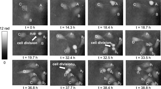 Fig. 2Gray-level-coded pseudo-3-D representation of the quantitative contrast images of living HBMECs in Fig. 1.  Video 1Fast-motion movie of quantitative DHM phase contrast images of living HBMECs for the whole experimental period of (2.1 MB, QuickTime). .  For further evaluation of the DHM phase contrast images, the maximum phase contrast , the maximum cell thickness , and the cell migration trajectories of all cells were determined, as described in Sec. 2. The typical size of the ROI that was used for two-dimensional cell tracking is indicated in Fig. 1 in the DHM phase contrast image for by a dashed box around cell C. During the evaluation procedure, the trajectories of the remaining daughter cells that were not detected by the automated cell tracking algorithm were started by manual selection after the cell division process. Figure 3 shows for each cell the temporal dependence of the maximum phase contrast as well as the corresponding cell thickness that is obtained from Eq. 1. Prior to the cell division, for cells A, B, and D, cell rounding is induced, which causes a significant increase of the maximum phase contrast and the cell thickness. The resulting peaks in the plots in Fig. 3 are marked with arrows. After the cell division for all cells, a decrease of and is detected. For cell C, which undergoes no cell division, only a few fluctuations of phase contrast and cell thickness are observed. Figure 4 shows the automated obtained cell migration -trajectories for all evaluated cells and demonstrates the reliability of the applied cell tracking algorithm. Fig. 3Time-dependent maximum phase contrast and time-dependent corresponding maximum cell thickness obtained from the quantitative contrast images in Fig. 1. 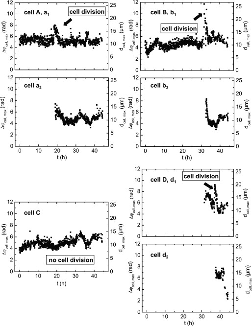 Fig. 4Two-dimensional quantitative tracking of the cells in the DHM phase-contrast images in Fig. 1. (a) Trajectories of cell A and daughter cells , after cell division; (b) trajectories of cell B and daughter cells , after cell division; (c) trajectory of cell C (no cell division is observed); and (d) trajectories of cell D and daughter cells , after cell division.  4.Discussion and ConclusionsThe results demonstrate the capabilities of DHM for dynamic cell division monitoring by simultaneous cell thickness measurement and two-dimensional cell tracking. The cell division is clearly detected by the phase contrast images in Figs 1 and 2, and by the temporal dependency of phase contrast and cell thickness demonstrated in Fig. 3. However, as slight changes of the integral cellular refractive index cannot be completely excluded during the cell division process, the obtained values for the cell thickness in Fig. 3 have to be handled carefully.26 A further increase of the measurement accuracy for the cell thickness may be achieved by DHM-based decoupling procedures29, 30 but requires more complex experimental equipment or measurements with different light wave-lengths and a suitable dispersive dye. As the -position data in Fig. 4 are obtained by the determination of the coordinates of the maximum phase contrast, the precision of the applied algorithm can be estimated to be sensitive to cell thickness fluctuations. Furthermore, the magnification of the applied experimental setup and disturbances in the phase contrast images due to scattering effects, e.g., by the cell culture medium, have to be taken into account. Thus, the error for the detection of the lateral cell position was estimated by the fluctuations of the curves in Fig. 4, which are found in the range of . These values are specific for the applied measurements setup and amount in the range of about 10% of the average lateral cell diameter. This is low in view of the cell-shape changes that are observed in the DHM phase contrast images in Fig. 1 and can be explained as follows: For the cell cycle phases in which the cells adhere on the substrate, the nucleoli predominate the coordinates of the maximum phase contrast. As the nucleoli are located in the nucleus, the resulting -values can be expected to be a good approximation of the cell center. The influence of cellular organelles other than the nucleoli is expected to be small due to the applied smooth filter of . This is supported by the small fluctuations in the -trajectories in Fig. 4 as well as by the fact that in the phase contrast images in Fig. 1, the cellular organelles other than the nucleoli appear only with a marginal contrast. During the cell rounding process, the maximum phase contrast is well defined by the center of the resulting spherical structure. Thus, also for this period of the cell cycle, a reliable detection of the cell center is possible. For the phases of the cell cycle in which the cells adhere on the substrate with thin morphology, our algorithm is expected to be more efficient than the evaluation of the DHM phase contrast images for two-dimensional cell tracking by classical edge detection algorithms. During the periods when the cells adhere, the thickness of the outer cell border areas is . Consequently, the cells appear with a low contrast of the boundaries in the DHM phase contrast images (see Fig. 1), which would affect the robustness of an edge detection–based determination of the lateral cell position. Following the approach of Barer,31 additional quantitative temporally resolved information about a concentration change of the intracellular substances may be obtained by dry mass measurements, as proposed previously.32, 33 However, this requires further research on the development and optimization of suitable robust image processing algorithms. In conclusion, the data in Figs. 1, 2, 3, 4 demonstrate the applicability of DHM for quantitative monitoring of the cell division processes during long-term time-lapse observations. DHM provides an efficient method for automated cell thickness monitoring, while simultaneously the two-dimensional cell migration trajectories are obtained. Furthermore, subcelluar regions with a higher molecular density than that of the surrounding cell compartments, such as nucleus and nucleoli, are visible in the phase contrast images. Possible applications of the method include the minimally invasive quantification of cell vitality in the research fields of toxin-mediated cell damage and tumor cell migration analysis in cancer research. AcknowledgmentsThis work was supported by grants from the German Federal Ministry of Education and Research (BMBF), project FKZ 13N9270 within the research focus program Biophotonics; the Deutsche Forschungsgemeinschaft (DFG), program Infections of the Endothelium SPP 1130 project KA 717/4-3; the Graduiertenkolleg GRK 1409; and by grants from the Interdisciplinary Center of Clinical Research (IZKF) Münster, Project No. Me2/023/08. ReferencesE. Cuche, P. Marquet, and C. Depeursinge,
“Simultaneous amplitude-contrast and quantitative phase-contrast microscopy by numerical reconstruction of fresnel off-axis holograms,”
Appl. Opt., 38 6694
–7001
(1999). https://doi.org/10.1364/AO.38.006994 0003-6935 Google Scholar
D. Carl, B. Kemper, G. Wernicke, and G. von Bally,
“Parameter-optimized digital holographic microscope for high-resolution living-cell analysis,”
Appl. Opt., 43 6536
–6544
(2004). https://doi.org/10.1364/AO.43.006536 0003-6935 Google Scholar
P. Marquet, B. Rappaz, P. J. Magistretti, E. Cuche, Y. Emery, T. Colomb, and C. Depeursinge,
“Digital holographic microscopy: a noninvasive contrast imaging technique allowing quantitative visualization of living cells with subwavelength axial accuracy,”
Opt. Lett., 30 468
–470
(2005). https://doi.org/10.1364/OL.30.000468 0146-9592 Google Scholar
C. J. Mann, L. Yu, C.-M. Lo, and M. K. Kim,
“High-resolution quantitative phase-contrast microscopy by digital holography,”
Opt. Express, 13 8693
–8698
(2005). https://doi.org/10.1364/OPEX.13.008693 1094-4087 Google Scholar
F. Charrière, J. Kühn, T. Colomb, F. Montfort, E. Cuche, Y. Emery, K. Weible, P. Marquet, and C. Depeursinge,
“Characterization of microlenses by digital holographic microscopy,”
Appl. Opt., 45 829
–835
(2006). https://doi.org/10.1364/AO.45.000829 0003-6935 Google Scholar
B. Kemper and G. von Bally,
“Digital holographic microscopy for live cell applications and technical inspection,”
Appl. Opt., 47 A52
–A61
(2008). https://doi.org/10.1364/AO.47.000A52 0003-6935 Google Scholar
G. von Bally, B. Kemper, D. Carl, S. Knoche, M. Kempe, C. Dietrich, M. Stutz, R. Wolleschensky, K. Schütze, M. Stich, A. Buchstaller, K. Irion, J. Beuthan, I. Gersonde, and J. Schnekenbuger,
“New methods for marker-free live cell and tumor analyis,”
Biophotonics: Vision for Better Healthcare, 301
–360 Wiley-VCH, Weinheim
(2006). Google Scholar
B. Kemper, D. Carl, A. Höink, G. von Bally, I. Bredebusch, and J. Schnekenburger,
“Modular digital holographic microscopy system for marker free quantitative phase contrast imaging of living cells,”
Proc. SPIE, 6191 61910T
(2006). https://doi.org/10.1117/12.662781 0277-786X Google Scholar
L. G. Alexopoulos, G. R. Erickson, and F. Guilak,
“A method for quantifying cell size from differential interference contrast images: validation and application to osmotically stressed chondrocytes,”
J. Microsc., 205 125
–135
(2001). https://doi.org/10.1046/j.0022-2720.2001.00976.x 0022-2720 Google Scholar
A. Barty, K. A. Nugent, D. Paganin, and A. Roberts,
“Quantitative optical phase microscopy,”
Opt. Lett., 23 817
–819
(1998). https://doi.org/10.1364/OL.23.000817 0146-9592 Google Scholar
G. Popescu, L. P. Deflores, J. C. Vaughan, K. Badizadegan, H. Iwai, R. R. Dasari, and M. S. Feld,
“Fourier phase microscopy for investigation of biological structures and dynamics,”
Opt. Lett., 29 2399
–2401
(2004). https://doi.org/10.1364/OL.29.002503 0146-9592 Google Scholar
T. Ikeda, G. Popescu, R. R. Dasari, and M. S. Feld,
“Hilbert phase microscopy for investigating fast dynamics in transparent systems,”
Opt. Lett., 30 1165
–1167
(2005). https://doi.org/10.1364/OL.30.001165 0146-9592 Google Scholar
J. Farinas and A. S. Verkman,
“Cell volume and plasma membrane osmotic water permeability in epithelial cell layers measured by interferometry,”
Biophys. J., 71 3511
–3522
(1996). https://doi.org/10.1016/S0006-3495(96)79546-2 0006-3495 Google Scholar
P. Tychinskii,
“Dynamic phase microscopy: is a dialogue with the cell possible?,”
Phys. Usp., 50 513
–528
(2007). https://doi.org/10.1070/PU2007v050n05ABEH006222 1063-7869 Google Scholar
V. P. Tychinskii,
“Coherent phase microscopy of intracellular processes,”
Phys. Usp., 44 617
–629
(2001). https://doi.org/10.1070/PU2001v044n06ABEH000841 1063-7869 Google Scholar
A. D. Aguirre, P. Hsiung, T. H. Ko, I. Hartl, and J. G. Fujimoto,
“High-resolution optical coherence microscopy for high-speed, in vivo cellular imaging,”
Opt. Lett., 28 2064
–2066
(2003). https://doi.org/10.1364/OL.28.002064 0146-9592 Google Scholar
E. A. Swanson, J. A. Izatt, M. R. Hee, D. Huang, C. P. Lin, J. S. Schuman, C. A. Puliafito, and J. G. Fujimoto,
“In vivo retinal imaging by optical coherence tomography,”
Opt. Lett., 18 1864
–1866
(1993). https://doi.org/10.1364/OL.18.001864 0146-9592 Google Scholar
Y. Zhao, Z. Chen, Z. Ding, H. Ren, and J. S. Nelson,
“Real-time phase-resolved functional optical coherence tomography by use of optical Hilbert transformation,”
Opt. Lett., 27 98
–100
(2002). https://doi.org/10.1364/OL.27.000098 0146-9592 Google Scholar
C. G. Rylander, D. P. Davé, T. Akkin, T. E. Milner, K. R. Diller, and A. J. Welch,
“Quantitative phase-contrast imaging of cells with phase-sensitive optical coherence microscopy,”
Opt. Lett., 29 1509
–1511
(2004). https://doi.org/10.1364/OL.29.001509 0146-9592 Google Scholar
A. K. Ellerbee, T. L. Reazzo, and J. A. Izatt,
“Investigating nanoscale cellular dynamics with cross-sectional spectral domain phase microscopy,”
Opt. Express, 15 8115
–8124
(2007). https://doi.org/10.1364/OE.15.008115 1094-4087 Google Scholar
C. Joo, K. H. Kim, and J. F. de Boer,
“Spectral-domain optical coherence phase and multiphoton microscopy,”
Opt. Lett., 32 623
–625
(2007). https://doi.org/10.1364/OL.32.000623 0146-9592 Google Scholar
P. Langehanenberg, B. Kemper, D. Dirksen, and G. von Bally,
“Autofocusing in digital holographic phase contrast microscopy on pure phase objects for live cell imaging,”
Appl. Opt., 47 D176
–D182
(2008). https://doi.org/10.1364/AO.47.00D176 0003-6935 Google Scholar
P. Langehanenberg, B. Kemper, and G. von Bally,
“Autofocus algorithms for digital-holographic microscopy,”
Proc. SPIE, 6633 66330E
(2007). https://doi.org/10.1117/12.727784 0277-786X Google Scholar
P. Langehanenberg, L. Ivanova, I. Bernhardt, S. Ketelhut, A. Vollmer, D. Dirksen, G. Georgiev, G. von Bally, and B. Kemper,
“Automated three-dimensional tracking of living cells by digital holographic microscopy,”
J. Biomed. Opt., 14 014018
(2009). https://doi.org/10.1117/1.3080133 1083-3668 Google Scholar
M. F. Stins, F. Gilles, and K. S. Kim,
“Selective expression of adhesion molecules on human brain microvascular endothelial cells,”
J. Neuroimmunol., 76 81
–90
(1997). https://doi.org/10.1016/S0165-5728(97)00036-2 0165-5728 Google Scholar
B. Kemper, D. Carl, J. Schnekenburger, I. Bredebusch, M. Schäfer, W. Domschke, and G. von Bally,
“Investigation of living pancreas tumor cells by digital holographic microscopy,”
J. Biomed. Opt., 11 034005
(2006). https://doi.org/10.1117/1.2204609 1083-3668 Google Scholar
S. Kosmeier, B. Kemper, P. Langehanenberg, I. Bredebusch, J. Schnekenburger, A. Bauwens, and G. von Bally,
“Determination of the integral refractive index of cells in suspension by digital holographic phase contrast microscopy,”
Proc. SPIE, 6991 699110
(2008). https://doi.org/10.1117/12.781125 0277-786X Google Scholar
B. Kemper, S. Kosmeier, P. Langehanenberg, G. von Bally, I. Bredebusch, W. Domschke, and J. Schnekenburger,
“Integral refractive index determination of living suspension cells by multifocus digital holographic phase contrast microscopy,”
J. Biomed. Opt., 12 054009
(2007). https://doi.org/10.1117/1.2798639 1083-3668 Google Scholar
B. Rappaz, P. Marquet, E. Cuche, Y. Emery, C. Depeursinge, and P. Magistretti,
“Measurement of the integral refractive index and dynamic cell morphotometry of living cells with digital holographic microscopy,”
Opt. Express, 13 9361
–9373
(2005). https://doi.org/10.1364/OPEX.13.009361 1094-4087 Google Scholar
B. Rappaz, F. Charrière, C. Depeursinge, J. Magistretti, and P. Marquet,
“Simultaneous cell morphometry and refractive index measurement with dual-wavelength digital holographic microscopy and dye-enhanced dispersion of perfusion medium,”
Opt. Lett., 33 744
–746
(2008). https://doi.org/10.1364/OL.33.000744 0146-9592 Google Scholar
R. Barer,
“Interference microscopy and mass determination,”
Nature (London), 169 366
–367
(1952). https://doi.org/10.1038/169366b0 0028-0836 Google Scholar
G. Popescu, Y. Park, N. Lue, C. Best-Popescu, L. Deflores, R. R. Dasari, M. S. Feld, and K. Badizadegan,
“Optical imaging of cell mass and growth dynamics,”
Am. J. Physiol.: Cell Physiol., 295 C538
–544
(2008). https://doi.org/10.1152/ajpcell.00121.2008 0363-6143 Google Scholar
B. Rappaz, E. Canob, T. Colomb, J. Kühn, V. Simanis, C. Depeursinge, P. J. Magistretti, and P. Marquet,
“Noninvasive characterization of the fission yeast cell cycle by monitoring dry mass with digital holographic microscopy,”
J. Biomed. Opt., 14 034049
(2009). https://doi.org/10.1117/1.3147385 1083-3668 Google Scholar
|


