
|
|
1.IntroductionThe measurement of ocular aberrations has been an issue of interest during the last few decades. Customized aberration correction by refractive surgery or static optical elements, high resolution imaging of the eye fundus, and dynamic and populational statistical studies have benefited from the use of objective aberrometers based on Hartmann-Shack or laser ray tracing wavefront sensors.1, 2, 3, 4, 5 During aberrometric measurements, the subject is generally instructed to fixate on a suitable target to keep the eye pupil at rest with respect to the aberrometer reference frame. However, involuntary fixational eye movements cause the eye to exhibit an erratic translation and torsional trajectory. The translational component, related to horizontal and vertical displacements, presents three main components:6, 7 drifts, a slow component with amplitude of 0.02 to ; fast microsaccades, with duration, amplitude of 0.22 to , and frequency of ; and tremors, with very low amplitude but very high temporal frequency . The torsional component describes the rotation of the eye around the line of gaze. The magnitude of these torsional movements is in angular terms superior to the translational ones. The work of van Rijn, van der Steen, and Collewijn established a range of .8 Other studies obtained smaller values around 9 and .10 The precise measurement and characterization of eye movements are a relevant task in areas of research such as visual optics, ophthalmology, and aberrometry.11, 12, 13, 14 There are several techniques developed to achieve this goal, such as those based on Purkinje images, corneal reflections, pupil images, retinal structures, and more recently, wavefront aberration data.12, 13, 14, 15 In the field of refractive surgery, most of the eye trackers are based on the analysis of video images of the pupil or of the corneal reflex (or both). These trackers typically present accuracies of the order of , or equivalently of lateral displacement of the pupil.16, 17, 18 Currently it is widely accepted that refractive surgery systems can benefit from including an efficient eye tracking system to measure and compensate for involuntary ocular movements. However, the use of eye trackers in eye aberrometry is not so extended, although the fixational ocular movements or displacements of the eye due to replacement of the patient are also present, reducing the repeatability of the measurements and increasing their uncertainty.19, 20, 21, 22, 23 Although fixational eye movements cause lateral displacements and cyclotorsions of the eye with respect to the wavefront sensor reference frame (WSRF), they give rise to nearly displacement-induced changes in the measured aberration.24, 25 Therefore, we focus on the effect of translational movements. If the eye displacements are known, the aberration coefficients measured in the aberrometer reference frame can be converted to transform them to the eye pupil reference frame (EPRF) by using a transformation matrix straightforwardly computed by different procedures.20, 21, 22 Better estimation of the ocular aberration can thus be achieved, with higher accuracy and reduced uncertainty, therefore leading to a potential improvement in the correction of ocular aberrations through refractive surgery or customized phase plates, and also to a better knowledge of their actual statistical properties. Most aberrometers present in market or research laboratories are based on Hartmann-Shack (HS) wavefront sensors. These devices estimate eye aberration from the displacements of the centroids of the focal spots of the microlens array. These centroids are determined by processing the raw images of the focal plane of the array taken by a charge-coupled device (CCD) detector. The use of these raw aberrometric images (AI) to get a coarse estimation of the pupil position and movement has been previously reported in the literature. In one example of application, the position is estimated with respect to a mask of concentric circles placed over the computer monitor.23 Other works proposed the use of the “centroid of the centroids” of the HS focal spots.13 The precision in the first approach is limited by the fact that the pupil rim, imaged onto the microlens array, gives rise to a blurred defocused border at the common focal plane of the microlenses, making it difficult to locate it accurately. In the second one, erroneous readings can be obtained either if the pupil image is not fully contained within the microlens array borders, or it moves less than the separation between two sampling elements, because (due to the unit weight assigned to each focal spot centroid) the overall centroid would keep constant despite the ocular movement. Estimating the pupil position and displacements from aberrometric images provides some practical advantages. It allows for avoiding the use of a synchronization unit and a conventional eye tracker with its additional optical path, thus simplifying the whole setup. In this work we demonstrate theoretically and experimentally the possibility of using the aberrometric images to track the eye pupil while measuring the ocular wavefront aberration, without some of the limitations of previous methods. Our pupil tracking proposal is based on estimating the eye movements by measuring the displacements of the overall centroid of the whole aberrometric image (see Fig. 1 , left). The approach described here does not require locating the defocused pupil border at the common focal plane of the microlens array, nor is it affected by the fact that the eye pupil may fall outside the microlens array region. Fig. 1Aberrometric image (left) and pupil image (right) acquired simultaneously with the Hartmann-Shack camera of the experimental setup when measuring the ocular aberrations of a human eye. 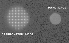 In Sec. 2 we introduce the theoretical background. In Sec. 3 we show the experimental setup and apparatus calibration procedure. Section 4 is devoted to the results obtained with human eyes. In the last section, we present the discussion and conclusions. 2.Theoretical BackgroundLet be the optical field at the exit pupil of the eye, where is the position vector in the pupil plane, is the amplitude, , where is the wavelength, and is the eye’s wave aberration (measured in units of length). Although not explicitly indicated in this equation, allowance is made for temporal variations of the eye aberration and temporal changes in the irradiance distribution, position, and size of the eye pupil.In a Hartmann-Shack setup, the optical field at the exit pupil of the eye is imaged onto a microlens array composed of convergent microlenses with focal distance , whose complex transmittance can be written as: where are the positions of the centers of the microlenses and are the corresponding microlens binary aperture functions (valued 1 inside the pupil and 0 otherwise). Equation 2 assumes that the area of the microlens array not belonging to the active regions of the microlenses is transparent.The field at the exit plane of the array, assuming for the sake of simplicity that the eye pupil is imaged onto it with unit magnification, is and the irradiance is given bythus reproducing the irradiance at the eye exit pupil (Fig 1, right). Note that as long as this irradiance distribution does not noticeably change with time inside the eye pupil, the displacements of its centroid are equal to the displacements of the geometrical center of the pupil. This allows estimating the eye movements using a suitable dedicated image channel in the Hartmann-Shack setup.We are interested, however, in avoiding the need of this additional imaging channel. After propagating a distance (usually, but not necessarily, equal to the focal distance of the microlenses), the field distribution gives rise to the well-known Hartmann-Shack pattern, here referred to as the aberrometric image (AI) (Fig. 1, left). Postprocessing this image, the displacements of the centroids of the focal spots, with respect to their reference positions, can be determined and the wave aberration can be estimated using any of the available approaches for wavefront reconstruction. To use this same image to assess the eye pupil displacements, let us see how its overall centroid (taking AI as a whole) relates to the centroid of the eye pupil irradiance distribution [Eq. 4]. It is well known that, under the Fresnel approximation for homogeneous media, the centroid of any light beam propagates between any two planes separated by a distance along a straight line, whose slope is proportional to the irradiance-weighted aberration gradient of the field at the initial plane26, 27 according to the expression: where and are the irradiance centroids at the final and initial plane, respectively, is the normalized irradiance at the initial plane, stands for the transverse gradient operator, is the wavefront’s optical path at the initial plane, and . All integrations are extended to the said plane.Equation 5 can be directly applied to the propagation of the overal irradiance centroid from the microlens array to the detection plane (at a distance ), where the aberrometric image is formed. In this case, is computed from the irradiance given by Eq. 4 and . Let us now consider that the eye pupil moves from its initial position to a new one, transversally displaced by a vector . The new centroid positions and obey the expression: where the prime, labeled , indicates that the eye’s wave aberration may (and usually does) change with time. Note that the microlens array phase transmittance is not affected by the eye movement. Subtracting Eq. 5 from Eq. 6, and assuming negligible irradiance changes except for those arising from the pupil displacement, we get:where we have substituted for , since in the case of no irradiance changes, the pupil irradiance centroid displaces the geometrical center of the pupil. Note that can be directly computed from the aberrometric images used by the HS sensor. From Eq. 7, is a good measure of as far as the contribution of the remaining integral terms being negligible. As we see, this turns out to be the case in typical situations.The second term on the right-hand side of Eq. 7 is the difference between the spatial averages across the eye pupil, taken at two different times, of the irradiance-weighted eye aberration slopes. If the irradiance distribution is spatially uniform (or rotationally symmetric, or even if it is spatially random with a very short correlation length), all aberration terms with even powers will make no net contribution to each of the aforementioned integrals. This includes defocusing due to accomodation fluctuations, a leading cause of temporal variation of the eye aberration. Odd-power terms will contribute to the integrals, but their net effect in Eq. 7 will depend on the differential eye aberration taken at two different times. To evaluate the order of magnitude of this effect, we used a temporal series of experimentally measured eye aberration coefficients, computing the resulting value of the term, where was modeled by the Stiles-Crawford expression proposed by Applegate and Lakshminarayanan.28 We found that for this series, the mean value of the bias term was of the order of and its rms fluctuation was , much smaller than the precission usually required for pupil tracking in eye aberrometry. On the other hand, the last integral in Eq. 7 is the difference between the irradiance-weighted averages of the phase slope of the microlens array with the eye pupil located at two different positions. If the eye pupil irradiance is spatially uniform and the pupil contains the whole microlens array active area, this integral cancels out. If the pupil is wholly contained within the active area of the microlens array or is partly outside it, the value of this integral is expected to be small, given that the contribution of each microlens not vignetted by the eye pupil will be zero. This strictly holds, as stated before, as long as the irradiance across the eye pupil is constant. This result is independent from any manufacturing aberration that the microlens may present. Small deviations from this nominal behavior can be expected if the irradiance is slowly variable across the pupil. To get an estimation of the magnitude of this last integral in Eq. 7, we evaluated it numerically for a typical aberrometric situation. In that calculus we modeled again the eye pupil irradiance distribution with the Stiles-Crawford expression proposed in Ref. 28. We considered a pupil diameter of , a HS sensor with 89 square microlenses of per side and focal length, and a fill factor of 100%. The integral result was 0.03 and for pupil displacements of 50 and , respectively. Thus the relative value of the bias induced by this term of Eq. 7 with respect to the magnitude of the pupil displacement is of the order of 6e-4. 3.Experimental Setup and CalibrationThe experimental setup for testing this approach consists of a HS aberrometer that incorporates an additional channel for monitoring the pupil. The sensor and monitoring channels form the images of the spots of the microlens array and the eye pupil onto the same camera chip (Orca 285, Hammamatsu Photonics, Iwata City, Japan). Figure 2 shows a drawing of the system setup. This arrangement allows for the acquisition of both images with the same camera, reducing the cost of the system and providing the necessary synchronization between both channels. The pupil channel was included to use the pupil image (PI) as an element of control. The displacement of the pupil measured using the centroid displacement of the eye pupil was used as the reference to which we compared the movement estimated from the AI (image of the pupil observed through the microlenses array). Figure 1 shows a typical image obtained with the camera (AI on the left and PI on the right). The microlens array used in our experiments was manufactured in our laboratory. It consists of 89 microlenses per side and focal length arranged in a square lattice. We illuminate the human eyes with a low coherence laser pointer with a central wavelength at and spectral bandwidth of . Thresholding of the camera images was performed to identify the background component, the aberrometric image, and the pupil image. The threshold level was obtained by trial and error, based on the visual stability of the shape of the thresholded AI. Figure 3 shows the thresholded aberrometric images of three consecutive pupil positions. The movement of the pupil was estimated from the displacement of the centroid of AI and PI with respect to the initial position. An artificial eye was used to perform the calibration. This consisted of a green Luxeon Star (Brantford, Ontario) LED (LXHL-MM1D) with an emission spectra centered in with bandwidth, a microscope objective that formed the image of the LED at the object focal plane of a focal length lens. The artificial eye pupil was generated with a circular diaphragm. The artificial eye was mounted over a precision linear stage to make the calibration. The calibration procedure was simple. We moved the artificial eye transversally across in steps of and registered, with the system’s camera at each step, both the aberrometric and pupil image. As we said before, each registered image was thresholded, and the centroids of AI and PI were computed to estimate the movement of the artificial eye with respect to its initial position. Polynomial linear fitting of the estimated displacements to the displacement of the precision linear stage was done. The results of the fitting were used to correct the displacements estimated from the aberrometric and pupil images. In the case of the pupil image, the root mean square error (rms) after calibration was with a maximum error of and a regression coefficient of 0.99. In the case of the aberrometric image, we got an rms of with a maximum error of and a regression coefficient of 0.99. We represented the centroids obtained from the PI in front of the ones achieved with the AI after performing the calibration (see Fig. 4 ), obtaining a regression coefficient of 0.99. It is clear from these results that the movements of the artificial eye can be estimated by using the aberrometric image. 4.Results with Human EyesWe have shown in the precedent section that the procedure designed for estimating the movement of the pupil from the AI works well with artificial eyes. Let us now test the proposal with human eyes. In this analysis the movement of the pupil estimated from the PI was used as the control element, against which we evaluate the performance of the pupil tracking based on the aberrometric image. We present here the results of three sequences obtained with two different eyes. We show in Table 1 the mean error, the root mean square error, and the signal-to-noise ratio (SNR) of the AI computed as the mean value of the difference between the plateau of the AI and the background level, divided by the rms of the intensity of the plateau. Table 1Mean bias and rms of the eye-tracking procedure in function of SNR of the AI.
Table 1 shows the high accuracy and precision achieved, similar to commercially available eye trackers. The value of the mean error was computed as the mean of the differences obtained for every position between the centers estimated from the centroid of the AI and PI. The rms is the root mean square value of the differences obtained between the estimated centers. In Table 1 we can also observe that, as all video-based eye trackers, its performance depends highly on the signal-to-noise ratio of the AI. Figure 5 shows one example application of the pupil tracking procedure. In particular, this figure presents the trajectory of one eye during a long-term measurement of ocular aberrations (circles for the positions estimated from the AI and triangles for the PI). Fig. 5Ocular movement trajectory estimated from the pupil image (triangles), and from the aberrometric image (circles). Data are obtained from the ocular aberrometric exploration of a human eye.  Finally, we used some of our aberrometric sequences to estimate the ocular wavefront, including information of the pupil position obtained with the proposed pupil tracking approach. We used 37 microlenses, and estimated 20 Zernike polynomials (excluding piston) over a pupil diameter of . We show in Table 2 the results of this analysis. To compare the estimation of the wavefront with respect to the EPRF and the WSRF, we computed the mean (⟨rms⟩) and standard variation of the modulus of the modal coefficients (neglecting the tilt components) estimated with respect to both frames. The average was done along the different measurements included on each aberrometric sequence. The related ocular trajectories are presented in Fig. 6 . Table 2Mean and standard deviation of the wavefront measurement sequences rms for three different subjects.
Table 2 shows the differences between the mean value and standard deviation of the ocular wavefront measured with respect to the EPRF and WSRF. Also, we can see that, for the particular sequences analyzed, the value of the wavefront standard deviation is lower in the EPRF. Additionally, as can be observed in the table, the magnitude of the difference between both reference frames depends highly on the ocular trajectory and ocular aberration, which agrees with the conclusions presented in Refs. 16, 19. 5.Discussion and ConclusionsOcular movements during steady-state fixation have been identified as one of the main sources of variability of measured ocular aberrations. Several authors have proposed different methods to estimate the position of the pupil before and during wavefront measurement.13, 23 We propose a different approach based on the measurement of the centroid of the aberrometric image. Estimating the pupil position and displacements from aberrometric images provides some practical advantages. It allows avoiding the use of a synchronization unit and a conventional eye tracker with its additional optical path, thus simplifying the whole setup. The proposed method is developed for measuring lateral pupil displacement, and it is not capable of measuring torsional movements. However, although the magnitude of torsional movements is (in angular terms) superior to the translational ones, their influence on wavefront estimation is significantly inferior.24, 25 Also, we want to clarify for those readers interested in eye tracking applications that the proposed method does not distinguish between eye translation due to head movements and rotations of the eye, it only measures the pupil displacement from a reference position independently on the origin of the movement. Additionally we point out that the presented method might be biased if there is asymmetrical pupil dilation between frames. In those cases a bias induced by the centroid shift would be added to the pupil displacement, caused by the asymmetrical change of shape. In its actual form our method does not detect the change of shape, and therefore no correction can be planned. However, a higher sophistication of the aberrometric image processing algorithm would allow for the extraction of additional information of the pupil shape from the pupil’s Fresnel shadow formed at the HS detection plane, and therefore could detect asymmetrical pupil dilation and decide what to do with those frames. In Sec. 3 we comment the use of the thresholding processing for segmentation of the aberrometric image previous to the centroid computation to distinguish those pixels that belong to the aberrometric image from those of the background level. In this work the threshold level is obtained by trial and error, based on the visual stability of the shape of the thresholded AI. However, there are different thresholding criterions that can be used to increase the performance of the pupil tracking system.29 In this sense, the use of complex thresholding algorithms or fitting algorithms, which take into account image histograms or the pixel SNR, would contribute to increase the precision of the pupil tracker.30, 31 Taking into account the presented numerical and experimental analysis, we consider that the proposed method can be used with existing Hartmann-Shack sensors, since no changes in the system setup would be involved. We also think that the method can be used with existing databases of Hartmann-Shack images for estimating the pupil position and then reprocess the wavefront measurements through available procedures20, 22, 32 to get a new set of estimated coefficients clear of the error induced by the ocular movements. By contrast, as we mentioned before, the performance of the method depends highly on the SNR of the aberrometric image, like all the methods based on centroid computation. So, further work must be done before any extensive use of the method occurs to optimize the aberrometric image acquisition-processing, and so reduce this dependence and increase confidence in the method. We want to also point out that the results presented in this work are limited by the theoretical assumptions made in the numerical validation (Fresnel propagation of the optical field and temporal constancy of the irradiance pupil distribution), and by the reduced number of eyes used in the experimental analysis. In conclusion we propose and demonstrate theoretically and experimentally (with artificial and human eyes) that Hartmann-Shack aberrometric images can be used not only for wavefront sensing but also to measure the position of the eye pupil during aberrometric measurement. We obtain with our method a root mean square error of , depending on the aberrometric image signal-to-noise ratio. Improvements in accuracy and precision are expected to be achieved in future works by improving the signal-to-noise ratio of the aberrometric image and selecting a better thresholding criterion. The knowledge of the relative position of the eye pupil with respect to the sensor reference frame allows expressing the estimated wavefront coefficients with respect to the pupil reference frame, and thus obtaining a better estimation of the ocular aberration, with higher accuracy and reduced uncertainty, which leads to a potential improvement in the correction of ocular aberrations through refractive surgery or customized phase plates. Moreover, it would lead to a better knowledge of the dynamics of the ocular aberrations, and to the achievement of statistical models that would contribute to the development of more accurate wavefront sensors. AcknowledgmentsThis work was supported by the Spanish Ministerio de Educación y Ciencia, grant FIS2005-05020-C03-02, Ministerio de Ciencia e Innovación, grant FIS2008-03884, and the European Regional Development Fund. Arines wants to acknowledge financial support from the Isidro Parga Pondal Programme 2009 (Xunta de Galicia, Spain). ReferencesJ. Liang, B. Grimm, S. Goelz, and J. F. Bille,
“Objective measurement of wave aberrations of the human eye with the use of a Hartmann-Shack wave-front sensor,”
J. Opt. Soc. Am. A, 11
(7), 1949
–1957
(1994). https://doi.org/10.1364/JOSAA.11.001949 0740-3232 Google Scholar
R. Navarro and M. A. Losada,
“Aberrations and relative efficiency of light pencils in the living human eye,”
Optom. Vision Sci., 74
(7), 540
–547
(1997). https://doi.org/10.1097/00006324-199707000-00023 1040-5488 Google Scholar
H. Hofer, L. Chen, G. Y. Yoon, B. Singer, Y. Yamauchi, and D. R. Williams,
“Improvement in retinal image quality with dynamic correction of the eye’s aberrations,”
Opt. Express, 8 631
–643
(2001). https://doi.org/10.1364/OE.8.000631 1094-4087 Google Scholar
R. Navarro, E. Moreno-Barriuso, S. Bará, and T. Mancebo,
“Phase plates for wave-aberration compensation in the human eye,”
Opt. Lett., 25 236
–238
(2000). https://doi.org/10.1364/OL.25.000236 0146-9592 Google Scholar
J. Porter, A. Guirao, I. G. Cox, and D. R. Williams,
“Monochromatic aberrations of the human eye in a large population,”
J. Opt. Soc. Am. A, 18
(8), 1793
–1803
(2001). https://doi.org/10.1364/JOSAA.18.001793 0740-3232 Google Scholar
F. Møller, M. L. Laursen, and A. K. Sjølie,
“The contribution of microsaccades and drifts in the maintenance of binocular steady fixation,”
Graefe's Arch. Clin. Exp. Ophthalmol., 244 465
–471
(2006). https://doi.org/10.1007/s00417-004-0989-5 0721-832X Google Scholar
R. V. Abadi and E. Gowen,
“Characteristics of saccadic intrusions,”
Vision Res., 44 2675
–2690
(2004). https://doi.org/10.1016/j.visres.2004.05.009 0042-6989 Google Scholar
L. J. Van Rijn, J. Van Der Steen, and H. Collewijn,
“Instability of ocular torsion during fixation: cyclovergence is more stable than cycloversion,”
Vision Res., 34 1077
–1087
(1994). https://doi.org/10.1016/0042-6989(94)90011-6 0042-6989 Google Scholar
D. Ott, S. H. Seidman, and R. J. Leigh,
“The stability of human eye orientation during visual fixation,”
Neurosci. Lett., 142
(2), 183
–186
(1992). https://doi.org/10.1016/0304-3940(92)90369-I 0304-3940 Google Scholar
M. Morisita and T. Yagi,
“The stability of human eye orientation during visual fixation and imagined fixation in three dimensions,”
Auris Nasus Larynx, 28
(4), 301
–304
(2001). https://doi.org/10.1016/S0385-8146(01)00100-6 0385-8146 Google Scholar
P. G. Gobbi, F. Carones, R. Brancato, M. Carena, A. Fortini, F. Scagliotti, A. Morico, and E. Venturi,
“Automatic eye tracker for excimer laser photorefractive keratectomy,”
J. Refract. Surg., 11
(3), S337
–342
(1995). 1081-597X Google Scholar
L. Diaz-Santana, J. Arines, P. Prado, and S. Bará,
“Translational and rotational pupil tracking using wavefront aberration data and image registration techniques,”
Opt. Lett., 31
(11), 1642
–1644
(2006). https://doi.org/10.1364/OL.31.001642 0146-9592 Google Scholar
L. N. Thibos, X. Hong, A. Bradley, and X. Cheng,
“Statistical variation of aberration structure and image quality in a normal population of healthy eyes,”
J. Opt. Soc. Am. A, 19
(12), 2329
–2348
(2002). https://doi.org/10.1364/JOSAA.19.002329 0740-3232 Google Scholar
M. Bueeler, M. Mrochen, and T. Seiler,
“Maximum permissible lateral decentration in aberration-sensing and wavefront-guided corneal ablation,”
J. Cataract Refractive Surg., 29 257
–63
(2003). https://doi.org/10.1016/S0886-3350(02)01638-3 0886-3350 Google Scholar
H. D. Crane and C. M. Steele,
“Double Purkinje eye tracker,”
(1981). Google Scholar
L. Vaissie and J. Rolland,
“Head mounted display with eyetracking capability,”
(2002). Google Scholar
J. M. Freeman, J. F. Freeman, and R. W. Williams,
“Eye tracking and positioning sysytem for a refractive laser system,”
(2001). Google Scholar
J. Taboada and W. Robinson,
“Eye tracking system and method,”
(1994). Google Scholar
E. Morrison and A. E. Green,
“Eye tracking system,”
(2002). Google Scholar
, “Product Description,”
(2007) Google Scholar
J. Arines, S. Bará, E. Pailos, and P. Prado,
“The contribution of the fixational eye movements to the variability of the measured ocular aberration,”
Ophthalmic Physiol. Opt., 29
(3), 281
–287
(2009). https://doi.org/10.1111/j.1475-1313.2009.00663.x 0275-5408 Google Scholar
S. Bará, J. Arines, J. Ares, and P. Prado,
“Direct transformation of Zernike eye aberration coefficients between scaled, rotated, and/or displaced pupils,”
J. Opt. Soc. Am. A, 23
(9), 2061
–2066
(2006). https://doi.org/10.1364/JOSAA.23.002061 0740-3232 Google Scholar
A. Guirao, D. Williams, and I. Cox,
“Effect of rotation and translation on the expected benefit of an ideal method to correct the eye’s higher-order aberrations,”
J. Opt. Soc. Am. A, 18
(5), 1003
–1015
(2001). https://doi.org/10.1364/JOSAA.18.001003 0740-3232 Google Scholar
J. Arines, P. Prado, S. Bara, and E. Acosta,
“Equivalence of least-squares estimation of eye aberrations in linearly transformed reference frames,”
Opt. Commun., 28
(10), 2716
–2721
(2008). 0030-4018 Google Scholar
N. Davies, L. Diaz-Santana, and D. Lara-Saucedo,
“Repeatability of ocular wavefront measurement,”
Optom. Vision Sci., 80
(2), 142
–150
(2003). https://doi.org/10.1097/00006324-200302000-00010 1040-5488 Google Scholar
S. Bará, T. Mancebo, and E. Moreno-Barriuso,
“Positioning tolerances for phase plates compensating aberrations of the human eye,”
Appl. Opt., 39 3413
–3420
(2000). https://doi.org/10.1364/AO.39.003413 0003-6935 Google Scholar
M. Bueeler, M. Mrochen, and T. Seiler,
“Required accuracy of lateral and torsional alignment in aberration-sensing and wavefront guided treatments,”
Proc. SPIE, 4611 185
–196
(2002). https://doi.org/10.1117/12.470594 0277-786X Google Scholar
S. Bará,
“Measuring eye aberrations with Hartmann-Shack wave-front sensors: Should the irradiance distribution across the eye pupil be taken into account?,”
J. Opt. Soc. Am. A, 20
(12), 2237
–2245
(2003). https://doi.org/10.1364/JOSAA.20.002237 0740-3232 Google Scholar
M. R. Teague,
“Irradiance moments: their propagation and use for unique retrieval of phase,”
J. Opt. Soc. Am., 72 1199
–1209
(1982). https://doi.org/10.1364/JOSA.72.001199 0030-3941 Google Scholar
R. A. Applegate and V. Lakshminarayanan,
“Parametric representation of Stiles-Crawford functions: normal variation of peak location and directionality,”
J. Opt. Soc. Am. A, 10
(7), 1611
–1623
(1993). https://doi.org/10.1364/JOSAA.10.001611 0740-3232 Google Scholar
D. Li, D. Winfield, and D. J. Parkhurst,
“Starburst: a hybrid algorithm for video-based eye tracking combining feature-based and model-based approaches,”
1
–8
(2005). Google Scholar
R. M. Haralick and L. G. Shapiro,
“Binary machine vision,”
Computer and Robot Vision, 1 14
–28 Addison-Wesley, Reading, MA
(1992). Google Scholar
J. Arines and J. Ares,
“Minimum variance centroid thresholding,”
Opt. Lett., 27
(7), 497
–499
(2002). https://doi.org/10.1364/OL.27.000497 0146-9592 Google Scholar
G. Dai,
“Wavefront expansion basis functions and their relationships,”
J. Opt. Soc. Am. A, 23 1657
–1668
(2006). https://doi.org/10.1364/JOSAA.23.001657 0740-3232 Google Scholar
|
|||||||||||||||||||||||||||||||||||||||||||||||


