|
|
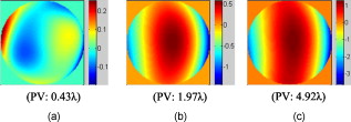
1.IntroductionFundus imaging is one of the most important techniques for detecting and diagnosing human diseases that influence the retina. Especially, the microscopic retinal imaging in vivo is a necessary method for ophthalmology research. But the aberration of the eye limits the resolution of the conventional fundus camera, scanning laser ophthalmoscopes (SLOs), and optical coherence tomography (OCT) systems.1, 2, 3 Their best lateral resolution is only , which is far from the diffraction limit of for a pupil. In 1997, Liang 4, 5 first obtained high-resolution retinal images through adaptive optics (AO). Subsequently AO was widely used for fundus imaging, not only equipped on fundus cameras, but also on SLO and OCT systems.6, 7, 8, 9, 10, 11, 12 AO enables the routine examination of single cells in the eye, such as photoreceptors and leukocytes, and provides the opportunity to noninvasively monitor normal retinal function, the progression of retinal disease, and the efficacy of therapies for disease at microscopic spatial scale.12 The fundus-imaging AO systems used by most of the researchers are based on deformable mirrors. In these adaptive optical systems, trial lenses and Badal systems are usually used to correct the defocus and astigmatism, and the deformable mirror mainly compensates the high-order aberration.10 Apart from deformable mirrors, liquid crystal spatial light modulators (LC-SLMs) have also been used in AO for astronomical and retinal imaging.13, 14, 15, 16, 17, 18 With the phase-wrapping method,19 some commercial LC-SLMs can compensate larger aberration compared with deformable mirrors, which is meaningful to extending the scope of AO imaging application. The first results for the 8-D myopic eye and 2-D astigmatic eye were obtained15 through closed-loop AO with an LC-SLM. As the wavefront corrector, the LC-SLM has a series of attractive characteristics such as compactness, high density, low cost, low drive voltage, and the possibility of batch production. Since an LC-SLM can modulate only polarized light, nearly half of the light energy will be lost in the closed-loop AO system.20, 21 As a result, the light illuminating the fundus must be enhanced to ensure that there is enough light energy reflected out of the eye and going into the image grabber, which is harmful for the human eye. Actually, half loss of the light energy could be avoided by the open-loop AO technique. In the open-loop AO system a polarizing beamsplitter is used to split the nonpolarized beam into two polarized beams. The polarized beam that matches the LC-SLM goes into the camera to form the image, and the other polarized beam goes into the wavefront sensor to generate the aberration signal. Also, the LC-SLM has good repeatability and linearity and no hysteresis, which makes it appropriate for open-loop correction.22 Although there is thermal hysteresis in the phase for some liquid crystal material,23 the thermal hysteresis has not been found in the nematic phase, and our LC-SLM is equipped with a temperature control unit to keep the temperature stably at . We constructed an open-loop AO system for retina imaging, and continuous high-resolution imaging of the fundus in vivo was realized. The fundus exposure energy density was reduced by nearly half compared with our previous closed-loop AO imaging system.15 2.Experiment Setup and MethodThe layout of the open-loop AO system is shown in Fig. 1 . It is similar to the closed-loop AO system we previously developed.15, 18 The imaging AO system is still based on the subjective accommodation of the human eye. The subject fixed at a target of away from the eye, and the imaging system is designed according to the subject’s accommodation state. Then the defocus can be precorrected without any external compensation method only if the subject’s eyesight is better than D. The target we used is a commercial LCD. A green cross icon (green, line width , layout size ) was sent to it on a black background. The fundus illumination light source is a commercial laser diode (wavelength ). Considering the axial chromatic aberration of the eye,24 the target was set away from the eye (5-D position), and the imaging part was designed for a view point away (4 D). Therefore, when the eye focuses on the target and accommodates to 5 D for the green light, the focus point for the imaging light would located at the 4-D position approximately, and ideally, there would be no defocus aberration for the imaging system. Fig. 1Open-loop AO system configuration: LD, laser diode; CBS: color beamsplitter; WBS, wedge beamsplitter; PBS: polarizing beamsplitter.  The wavefront corrector we used is a liquid crystal on silicon device (Boulder Nonlinear Systems: XY Series Spatial Light Modulators) filled with parallel alignment nematic liquid crystal. The wavefront sensor (WFS) is a Shack-Hartmann (SH-WFS). The parameter details of the LC-SLM and the SH-WFS are listed in Table 1 . In the AO system, the LC-SLM and the WFS both worked on the Zernike polynomial (only the first- to fifth-order polynomials were used), i.e., the WFS decomposed the wavefront aberration into Zernike coefficients and the control signal of the LC-SLM was calculated from the Zernike polynomial. Figure 2 shows the gray-scale map for , which is just the control signal of the LC-SLM. The LC-SLM, the WFS, and the human pupil are conjugated with each other through the lenses L3, L2, and L1, and the conjugated ratio is designed as 7.5:4.3:6 (LC-SLM, WFS, eye pupil) due to the size of the LC-SLM and the WFS. A hole is placed at the image position to block environmental stray light and the unwanted diffraction orders of light introduced by the LC-SLM. Fig. 2Wavefront measured by the WFS with and without the half-wave plate inserted: (a) the gray-scale map sent on the LC-SLM, (b) the wavefront with the half-wave plate, and (c) the wavefront without the half-wave plate. The unit of the color bar is wavelength. (Color online only.)  Table 1The parameters details of the SH-WFS and the LC-SLM.
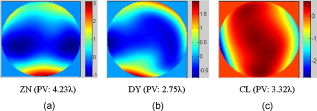
Since the LC-SLM can modulate only the matched polarized light, in the closed-loop AO system a polarizer was used15, 18 to select the linearly polarized light matched with the LC-SLM. For this open-loop AO system, a polarization beamsplitter (PBS) instead of a polarizer is used to split the beam into two polarized beams, one of which is well matched with the LC-SLM. The matched polarized beam could be modulated by the LC-SLM and reflected into the CCD camera to form the image, while the other beam could not be modulated and transmittes into the WFS to generate the aberration signal. As a result, the WFS could not detect the corrected wavefront during the correction loop. When the open-loop correction operating, the WFS detects the whole aberration, but not the residual continuously, and the LC-SLM corrects the aberration in real time. However, the WFS must be able to detect the action of the LC-SLM well when registering the LC-SLM to the WFS. A half-wave plate (WP) is inserted between the LC-SLM and the PBS to rotate the polarization direction of the light , and then a beam well modulated by the LC-SLM would transmit into the WFS. Figure 2 shows the effect of the PBS and the half WP. The gray-scale map of was sent to the LC-SLM and the wavefronts were measured by the WFS in relative mode, which means that the initial system aberration was subtracted. The peak-to-valley (PV) values of the wavefront with and without the half-WP were and , respectively, and the ideal PV values were and . Therefore, we could conclude that the matched polarized light could be modulated very well, while the vertical polarized light could not be modulated at all. Compared with the primary open-loop design,25 this configuration is more compact and the correction precision would be better because the two beams for wavefront detection and imaging transmition in the common path. The illuminating light source we used was a commercial laser diode (LD) with output wavelength (power adjustable). Because of the coherence of the laser, the speckle noise deteriorates the image severely. It is known that methods to reduce the laser speckle include using a rotating random phase plate, using multiple illumination tones, using the optical feedback effect, and so on. In this system, we used a rotating scatter plate (thin frosted glass) to reduce the speckle.26 Figure 3 shows the effect of the rotating frosted glass. The laser speckle pattern when the frosted glass is removed or static is almost the same, while the speckle is thoroughly reduced with the frosted glass rotating. To minimize the light loss caused by the scattering of the frosted glass, the laser was first focused by a lens to form a light spot on the frosted glass. The laser spot was scattered by the frosted glass and focused on the eye fundus to illuminate a circle area of diameter, which is calculated according to the statistical average eye axial length and no refractive error. The laser spot was also used as the beacon light; that is, the laser spot on the fundus was wholly used to measure the eye aberration, which enlarged the spot size in the SH-WFS from 40 (ideal point beacon) to . The size of the isoplanatic patch in the eye is about , corresponding27 to isoplanatic angle . Thus, the aberration would be the average of the field, which is in the range of the isoplanatic patch. Fig. 3Resolution target imaged based on the optical system shown in Fig. 1. A lens (focal length ) was placed at the position of pupil and the resolution target was placed approximately from the lens. Then the position of the resolution target was adjusted finely until the image grabbed by the camera was the clearest. (a) The resolution target image when illuminated by the laser diode directly, (b) the resolution target image with the frosted glass static, and (c) the image with the frosted glass rotating.  To eliminate the ghost image from illumination light and the target light, we used a wedge beamsplitter (WBS) instead of a parallel beamsplitter. The additional astigmatism aberration induced by the splitter is about (rms) due to the fact that its wedge angle is and its thickness is . The ratio between the transmission and reflection for the WBS is 9:1. When imaging the fundus, it was illuminated continuously for and the irradiance on the retina was , which is approximately of the maximum permissible exposure (MPE) according to28 ANSI.Z136.1-2007. The target LCD is dark, so that it will not cause the eye to shrink the pupil size. We confirmed that under this illuminating condition, subjects could see the target icon clearly and the pupil could dilate to larger than the designed stop size of without drug dilation and cyclopleging. Figure 4 shows the pupil image after of illumination. 3.Experiment ResultsFirst, the open-loop correction precision was tested by using a superluminescent light-emitting diode (SLED, ) with single-mode fiber output. A lens (focal length ) was set at the position of pupil (Fig. 1). And the fiber was set approximately from the lens. Thus, a simple eye model was constructed, and the fiber image formed by the lens located approximately from the lens. Because the diameter of the fiber was only about of the object space resolution limit of the model eye system, the fiber could be considered as a point light source. Thus, the image of the SLED could present the point spread function of the system. The minimum aberration of the system was (PV value) after careful calibration, as shown in Fig. 5 . The correspondingly SLED images before and after correction are shown in Figs. 6 and 7 (a1) and 7(a2), respectively. Then, the lens was tilted to introduce additional aberration. Two examples are presented here. The wavefront aberration is shown in Fig. 5, and the corresponding SLED images before and after open-loop correction are shown in Figs. 6 and 7, respectively. The Strehl ratio was directly calculated from the SLED images and the values were all better then 0.8 after correction. Thus, we can conclude that the optical system reached the diffraction limit with open-loop correction, although the initial wavefront aberration was nearly . Fig. 6SLED images before correction. The Strehl ratio for (a) was 0.56 and the Strehl ratio for (b) and (c) was smaller than 0.01.  Fig. 7SLED images after open-loop correction. The Strehl ratios after aberration correction for (a), (b), and (c) were 0.872, 0.823, and 0.807 respectively. The exposure time for (a2), (b2), and (c2) were 2 times those of (a1), (b1), and (c1), so the light distribution around the Ariy disk could be seen clearly. Note (a1) and (a2), (b1) and (b2), and (c1) and (c2) and Figs. 6, 6, 6 correspond to Figs. 5, 5, 5.  In the experiment, three subjects were tested. They are NZ with normal vision (0 D, old), DY ( D, old), and CL ( D, old). The target was set approximately off-axis, so the imaged area of the fundus was about from the fovea. The exposure time for the imaging camera was set at and the working frequency of the WFS was . First, several retina images before correction were recorded and the aberration was tested repeatedly. Then the open-loop correction loops were included on and the retina images were recorded simultaneously. The whole process took . The aberration of the three subjects is shown in Fig. 8 and the PV values of the aberration are , , and . Note that the defocus coefficients decomposed from the aberration of NZ, DY, and CL are , , and , respectively. Thus, the subjective accommodation errors for NZ and DY are 0.19 and 0.12 D. The defocus aberration for CL is mainly caused by that the chromatic refractive error of CL and was smaller than 1 D. The retina images for the three subjects before and after open-loop correction are shown in Figs. 9 and 10 , respectively. We can see that after open-loop correction, the AO imaging system reaches the resolution of a single photoreceptor cell. To quantify the improvement in retinal image quality we calculated the image rms contrast (the standard deviation of the pixel gray values) and the power spectrum. The rms contrast of the images is enhanced from 14, 9.4, and 13.8 to 21, 17.2, and 20.3 for the three subjects, respectively. Figure 11 shows the image power spectrum for subject CL with open-loop correction and without correction. The power spectrum is improved significantly with the open-loop correction, especially for the cone spatial frequency 70 to . Fig. 10Retina images for (a) ZN, (b) DY, and (c) CL after correction. The scale bars all represent .  Fig. 11Radially averaged retinal image power spectra for subject CL without correction and with open-loop correction of the eye’s aberrations.  Finally, continuously correction and imaging were performed for the subject CL. The results are shown in Video 1 . The video was recorded at 30 frames per second (fps) for about , but it was displayed slowly at to ensure that every frame was adequately shown. In the videos, the fundus images before and during correction were all recorded, so that we can get an intuitive estimate on the effect of open-loop correction. To illustrate the repeatability of cone identification between different imaging sessions, an asterisk is inserted near one of the bright cones, as shown in the video sample image. We can see that we can track the cone very well in the video. Although nearly half of the frames were blurred severely by the intermittent moving of the fundus, many clear images were still obtained under the condition of a exposure time and lack of dilation and cyclopleging. Video 1Raw videos of the fundus for CL before and during open-loop correction (QuickTime, 1.46 MB). .  The resolution of the fundus imaging system is improved significantly by the continuous open-loop correction. The definition of retina image is as good as the closed-loop AO fundus camera.7, 8, 15 The cone can be tracked very well in the continuous image session. However, the contrast of the retina images is poor compared with the images obtained through an AO SLO system. This is so because the AO fundus camera system can compensate only the aberration, but can not filter out the unwanted light reflected by the other layers of the retina, which is the particular advantage of the SLO system. 4.ConclusionBased on the open-loop control theory for LC-SLMs, an AO system for fundus imaging in vivo was constructed. The light energy efficiency was increased by a factor of 2 compared with the closed-loop AO system. Thus, the light energy entering the eye could be cut half and it would be much safer for the human eye. In the system, only one single commercial diode laser with a diffuser was used to illuminate the fundus, which made the system compact. The common path open-loop structure was also helpful to increase the correction precision. With the subjective accommodation method, three subjects with different vision were tested. The accommodation error was smaller than 0.2 D for the subjects whose vision was as good as 5 D. The images of the fundus in vivo proved that the imaging system reached the resolution of a single photoreceptor cell with open-loop correction. Continuous imaging for was obtained for one subject without drug dilation and cyclopleging. The open-loop AO fundus imaging system is based on the subjective accommodation method, so the active cooperation of the subjects is necessary. A subject is required to keep his or her eye stable for when required to capture a continuous image session. The AO system could not be applied to some special subjects whose pupils can not dilate enough naturally, because drug dilation is not used. AcknowledgmentThis work was supported by the National Natural Science Foundation (Grants No. 60578035, No. 50473040, and No. 60736042). ReferencesR. Navarro, E. Moreno, and C. Dorronsoro,
“Monochromatic aberrations and point spread functions of the human eye across the visual field,”
J. Opt. Soc. Am. A, 15 2522
–2529
(1998). https://doi.org/10.1364/JOSAA.15.002522 0740-3232 Google Scholar
A. Guirao, J. Porter, and D. R. Williams,
“Calculated impact of higher-order monochromatic aberrations on retinal image quality in a population of human eyes,”
J. Opt. Soc. Am. A, 19 1
–8
(2002). https://doi.org/10.1364/JOSAA.19.000001 0740-3232 Google Scholar
H. Hofer, P. Artal, B. Singer, J. Aragon, and D. Williams,
“Dynamics of the eyes wave aberration,”
J. Opt. Soc. Am. A, 18 497
–506
(2001). https://doi.org/10.1364/JOSAA.18.000497 0740-3232 Google Scholar
J. Liang, B. Grimm, S. Goelz, and J. Bille,
“Objective measurement of the wave aberrations of the human eye with the use of a Hartmann-Shack wave-front sensor,”
J. Opt. Soc. Am. A, 11 1949
–1957
(1994). https://doi.org/10.1364/JOSAA.11.001949 0740-3232 Google Scholar
J. Liang, D. R. Williams, and D. T. Miller,
“Supernormal vision and high-resolution retinal imaging through adaptive optics,”
J. Opt. Soc. Am. A, 14 2884
–2891
(1997). https://doi.org/10.1364/JOSAA.14.002884 0740-3232 Google Scholar
R. Zawadzki, S. Jones, S. Olivier, M. Zhao, B. Bower, J. Izatt, S. Choi, S. laut, and J. Werner,
“Adaptive-optics optical coherence tomography for high-resolution and high-speed 3D retinal in vivo imaging,”
Opt. Express, 13 8532
–8546
(2005). https://doi.org/10.1364/OPEX.13.008532 1094-4087 Google Scholar
H. Hofer, L. Chen, G. Y. Yoon, B. Singer, Y. Yamauchi, and D. R. Williams,
“Improvement in retinal image quality with dynamic correction of the eye’s aberrations,”
Opt. Express, 18 631
–643
(2001). https://doi.org/10.1364/OE.8.000631 1094-4087 Google Scholar
J. Rha, R. S. Jonnal, K. E. Thorn, J. Qu, Y. Zhang, and D. T. Miller,
“Adaptive optics flood-illumination camera for high speed retinal imaging,”
Opt. Express, 14 4552
–4569
(2006). https://doi.org/10.1364/OE.14.004552 1094-4087 Google Scholar
A. Roorda, F. Romero-Borja, W. J. Donnelly, and H. Queener,
“Adaptive optics scanning laser ophthalmoscopy,”
Opt. Express, 10 405
–412
(2002). 1094-4087 Google Scholar
E. J. Fernández, I. Iglesias, and P. Artal,
“Closed-loop adaptive optics in the human eye,”
Opt. Lett., 26 746
–748
(2001). https://doi.org/10.1364/OL.26.000746 0146-9592 Google Scholar
D. U. Bartsch, L. Zhu, P. C. Sun, S. Fainman, and W. R. Freeman,
“Retinal imaging with a low-cost micromachined membrane deformable mirror,”
J. Biomed. Opt., 7 451
–457
(2002). https://doi.org/10.1117/1.1483083 1083-3668 Google Scholar
D. R. Williams and J. Porter,
“Development of adaptive optics in vision science and ophthalmology,”
1
–11
(2006). Google Scholar
D. Dayton, J. Gonglewski, S. Restaino, J. Martin, J. Phillips, M. Hartman, P. Kervin, J. Snodgress, S. Browne, N. Heimann, M. Shilko, R. Pohle, B. Carrion, C. Smith, and D. Thiel,
“Demonstration of new technology MEMS and liquid crystal adaptive optics on bright astronomical objects and satellites,”
Opt. Express, 10 1508
–1519
(2002). 1094-4087 Google Scholar
T. Shirai,
“Liquid-crystal adaptive optics based on feedback interferometry for high-resolution retinal imaging,”
Appl. Opt., 41 4013
–4023
(2002). https://doi.org/10.1364/AO.41.004013 0003-6935 Google Scholar
Q. Mu, Z. Cao, C. Li, B. Jiang, L. Hu, and L. Xuan,
“Accommodation-based liquid crystal adaptive optics system for large ocular aberration correction,”
Opt. Lett., 33 2898
–2900
(2008). https://doi.org/10.1364/OL.33.002898 0146-9592 Google Scholar
F. Vargas-Martín, P. M. Prieto, and P. Artal,
“Correction of the aberrations in the human eye with a liquid-crystal spatial light modulator: limits to performance,”
J. Opt. Soc. Am. A, 15 2552
–2562
(1998). https://doi.org/10.1364/JOSAA.15.002552 0740-3232 Google Scholar
P. M. Prieto, E. J. Fernández, S. Manzanera, and P. Artal,
“Adaptive optics with a programmable phase modulator: applications in the human eye,”
Opt. Express, 12 4059
–4071
(2004). https://doi.org/10.1364/OPEX.12.004059 1094-4087 Google Scholar
C. Li, M. Xia, B. Jiang, Q. Mu, S. Cheng, and L. Xuan,
“Retina imaging system with adaptive optics for the eye with or without myopia,”
Opt. Commun., 282 1496
–1500
(2009). https://doi.org/10.1016/j.optcom.2008.12.048 0030-4018 Google Scholar
Y. Liu, Z. Cao, D. Li, Q. Mu, L. Hu, X. Lu, and L. Xuan,
“Correction for large aberration with phase-only liquid-crystal wavefront corrector,”
Opt. Eng., 45 128001
(2006). https://doi.org/10.1117/1.2405356 0091-3286 Google Scholar
H. B. Klein Brink and G. J. van Blokland,
“Birefringence of the human foveal area assessed in vivo with Mueller-matrix ellipsometry,”
J. Opt. Soc. Am. A, 5 49
–57
(1988). https://doi.org/10.1364/JOSAA.5.000049 0740-3232 Google Scholar
E. Gotzinger, M. Pircher, M. Sticker, A. F. Fercher, and C. K. Hitzenberger,
“Measurement and imaging of birefringent properties of the human cornea with phase-resolved, polarization-sensitive optical coherence tomography,”
J. Biomed. Opt., 9 94
–102
(2004). https://doi.org/10.1117/1.1629308 1083-3668 Google Scholar
C. Li, M. Xia, Q. Mu, B. Jiang, and L. Xuan,
“High-precision open-loop adaptive optics system based on LC-SLM,”
Opt. Express, 17 10774
–10781
(2009). https://doi.org/10.1364/OE.17.010774 1094-4087 Google Scholar
S. Sarmento, P. S. Carvalho, M. R. Chaves, F. Pinto, and H. T. Nguyen,
“Anomalous thermal hysteresis in the phase of , revealed by dielectric measurements,”
Liq. Cryst., 28 1839
–1845
(2001). https://doi.org/10.1080/02678290110086532 0267-8292 Google Scholar
L. N. Thibos, M. Ye, X. Zhang, and A. Bradley,
“The chromatic eye: a new reduced-eye model of ocular chromatic aberration in humans,”
Appl. Opt., 31 3594
–3600
(1992). https://doi.org/10.1364/AO.31.003594 0003-6935 Google Scholar
Q. Mu, Z. Cao, D. Li, L. Hu, and L. Xuan,
“Open-loop correction of horizontal turbulence:system design and result,”
Appl. Opt., 47 4297
–4300
(2008). https://doi.org/10.1364/AO.47.004297 0003-6935 Google Scholar
C. Li, B. Jiang, M. Xia, S. Cheng, and L. Xuan,
“Laser speckle reduction in retina imaging illumination,”
Acta Opt. Sin., 28 2245
–2249
(2008). https://doi.org/10.3788/AOS20082812.2245 0253-2239 Google Scholar
A. Dubinin, T. Cherezova, A. Belyakov, and A. Kudryashov,
“Anisoplanatism in human retina imaging,”
Proc. SPIE, 5894 589409
(2005). https://doi.org/10.1117/12.619429 0277-786X Google Scholar
American National Standards Institute, American National Standard for the Safe Use of Lasers, Laser Institute of America, Orlando, FL
(2007). Google Scholar
|
||||||||||||||||||||||||