|
|
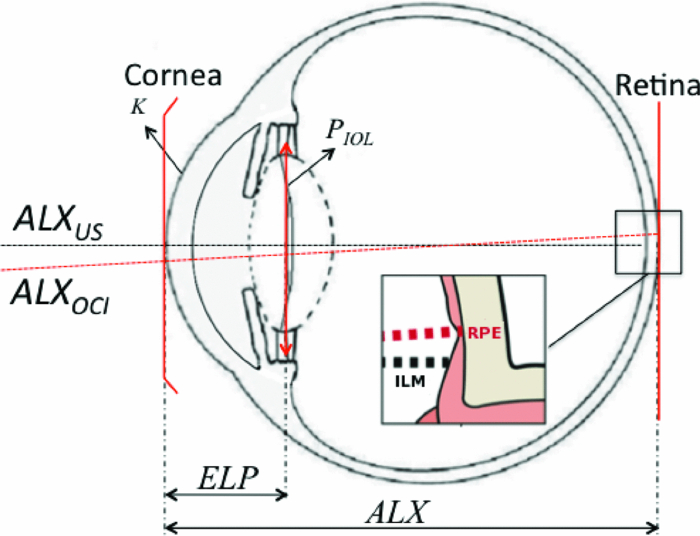
1.IntroductionDefocus is one of the most common and important sources of image degradation in the visual system that needs to be compensated. Defocus is represented by the refractive error (measured in diopters, D), which accounts for the mismatch being between eye power and eye length. Symmetrical defocus caused by myopia, hyperopia, and presbyopia as well as nonsymmetrical defocus caused by astigmatism have long been corrected by means of spectacles and contact lenses. With the development of new materials, instruments, and surgical techniques in ophthalmology, great progress has been achieved in the compensation of defocus, with optical design playing an essential role. Remarkable achievements in the last few decades are based on a permanent change in some physiological component of the optical system of the eye: corneal refractive surgery (CRS) to modify the corneal curvatures, implantation of intraocular lenses (IOLs), and combined solutions. New IOL designs need, on the one hand, theoretical eye models able to predict optical imaging performance 1, 2 and on the other hand, testing methods, 3, 4 verification through in vitro and in vivo measurements, 5, 6 and clinical validation.7 Not only does the implant of an IOL require a precise calculation but also an accurate position inside the eye. Otherwise, the effects of IOL misplacements degrade the image very quickly.8 According to Olsen,9 despite the efforts to target IOL power calculations for a refractive prediction <0.5 D (absolute error), ∼90% of cases fall within ±1.0 D and 99.9% within ±2.0 D of their targets. Higher errors are obtained in long and short eyes and patients that have undergone prior CRS. The blur due to defocus establishes the narrowest limits for acceptability. The defocus associated with a refractive error ranging in absolute value from 0.5 to 1.0 D has been classified from troublesome to objectionable (for a 5-mm effective pupil and black letter targets).10 Consequently, some postsurgical refractive errors may require further neutralization. To this end, corneal ablation to modify the curvature of the anterior surface of the cornea can be effective. This is in fact the preferred option in many cases, but it is not always recommendable or even possible. For instance, many patients that currently need cataract surgery underwent cornea ablation in their eyes some time ago. It is not unusual to find cases that are the result of a not very refined application of the ablation technique at its early stages—cases for which the resulting corneal thickness would not admit a second ablation in safe conditions. In this paper, we focus on the role of IOL in defocus correction and consider the modification of other ocular parameters to compensate for possible refractive error after the IOL implant. In some problematic cases (corneal transplantation, ectasies), we explore the possibility of modifying some less conventional ocular parameters. Our analysis aims to determine which components of the eye would be the most advantageous to modify provided the necessary biocompatible materials were available. 2.IOL Power Formulae and First-Order Characterization of Anterior EyeThe replacement of the crystalline lens for an IOL is one of the most effective ways to compensate for both symmetric defocus and astigmatism. Assuming the thin-lens equation in first-order approximation, the IOL power (P IOL) can be computed from the difference between the vergence of the exit or image beam (X [TeX:] $^\prime$ ) and the vergence of the incident or object beam (X), that is, [TeX:] $P_{\rm IOL} = X^\prime - X$ .11 These vergences are given by X = n q/z and [TeX:] $X^\prime = {{n_v } \mathord{/ {\vphantom {{n_v } {z^\prime }}} \kern-\nulldelimiterspace} {z^\prime }}$ , where n q, n v are the refractive indexes of aqueous and vitreous humors, and z and z ′ the distances of the object and the image to the IOL plane (thin lens in Fig. 1), respectively. An object at infinity is imaged by a cornea with refractive power K at its focal plane (F [TeX:] $^\prime$ ), placed at a distance n q/K from its back principal plane (H [TeX:] $^\prime$ ), which is next to the anterior vertex of the cornea in the Gullstrand eye (GE) model.1 It is widely known that this model does not correspond to real individual eyes. Nevertheless, despite the many limitations and simplifications of the Gullstrand four-surface model, it has been long used to generically describe the imaging optical design of the eye. We also consider the Gullstrand model to illustrate our analysis with some examples in the following sections. Assuming that the distance between the corneal anterior vertex and the IOL, named the effective lens position (ELP), can be predicted, then the object distance for the IOL is given by z = n q/K – ELP. The distance from the IOL plane to the retinal image is z ′ = ALX – ELP, being the axial length of the eye (ALX), the distance between the anterior vertex of the cornea and the retina. From all these considerations, the first-order formula for IOL power is Eq. 1[TeX:] \documentclass[12pt]{minimal}\begin{document}\begin{equation} P_{{\rm IOL}} = X' - X = \frac{{n_{\rm v} }}{{{\rm ALX} - {\rm ELP}}} - \frac{{n_{\rm q} }}{{\left({n_{\rm q} /K} \right) - {\rm ELP}}}.\end{equation}\end{document}2.1.Axial Length of the Eye (ALX)This is an essential measurement in the IOL power calculation: a 0.1-mm error in ALX is equivalent, approximately, to a refractive error of 0.27 D in the spectacle plane. But ALX has a different definition and precision depending on the measuring technique. Using ultrasound biometry ALXUS is the distance measured from the anterior corneal vertex on the optical axis to the internal limiting membrane of the retina (ILM in Fig. 1). The common uncertainty of this technique is about 0.15 mm. Using optical coherence interferometry ALXOCI is the distance, measured on the visual axis, from the anterior corneal vertex to the retinal pigment epithelium (RPE in Fig. 1). The uncertainty of this technique is typically about 0.01 mm. The advantages and drawbacks of these two biometric methods in clinical practice have been detailed by researchers and clinicians elsewhere. 9, 13, 14 2.2.Prediction of the ELPFrom the early formulas, many efforts have been made to improve the IOL power calculation and the accuracy in predicting the postoperative ELP. In this evolution, the formulas derived from a mathematical description of the optical system of the eye have been combined with other formulas based on statistical analysis of a large number of cases. As a result, there are four generations of IOL formulas whose significance and mathematical descriptions are reviewed in Refs. 9, 12, 13. 2.3.Optical Characterization of the CorneaThe corneal power (typically, 43 D of ∼60 D of the whole eye) is one of the most important piece of data in IOL power calculation formulas. The refractive power of the anterior corneal surface is easily measurable by keratometry or topography with precisions of 0.018 mm (0.1 D), approximately, but the posterior surface geometry has been technically more difficult to determine. Initially, a simplified single-surface model was adopted for the cornea [Fig. 2a], whose refractive power is Eq. 2[TeX:] \documentclass[12pt]{minimal}\begin{document}\begin{equation} P_{\rm s} = \frac{{n_{\rm s} }}{{f_{\rm s} }} = \frac{{(n_{\rm s} - n_{\rm a})}}{{R_1 }},\end{equation}\end{document}Nowadays, the posterior surface of the cornea can be characterized with a precision of ∼0.16 D (0.03 mm) using the slit-scan topography or the Scheimpflug topography. Consequently, it is appropriate to apply a better approximation that considers a thick lens model for the cornea [Fig. 2b], that is, an association of three optical materials with refractive indexes: n a (air), n c (cornea), and n q (aqueous humor) and two spherical surfaces of radii R 1 and R 2 separated by a distance e. More advanced models consider the asphericity of the cornea and its influence in the aberrations of the eye; 2, 19, 20, 21 however, because we are interested in defocus, a first-order approach and spherical surfaces will suffice in our study. In such a context, the paraxial characterization of the cornea is given by the following expressions of the power: Eq. 3[TeX:] \documentclass[12pt]{minimal}\begin{document}\begin{equation} P_{\rm d} = \frac{{n_{\rm q} }}{{f_{\rm d} }} = P_1 + P_2 - \frac{e}{{n_{\rm c} }}P_1 P_2 \end{equation}\end{document}Eq. 4[TeX:] \documentclass[12pt]{minimal}\begin{document}\begin{equation} V_1 H = - \frac{{en_{\rm a} P_2 }}{{eP_1 P_2 - n_{\rm c} \left({P_1 + P_2 } \right)}},\end{equation}\end{document}Eq. 5[TeX:] \documentclass[12pt]{minimal}\begin{document}\begin{equation} V_2 H' = \frac{{en_{\rm q} P_1 }}{{eP_1 P_2 - n_{\rm c} \left({P_1 + P_2 } \right)}}.\end{equation}\end{document}Eq. 6[TeX:] \documentclass[12pt]{minimal}\begin{document}\begin{equation} P_{{\rm bv}} = \frac{{n_{\rm q} }}{{f_{{\rm bv}} }} = \frac{{n_{\rm q} }}{{f_{\rm d} + V_2 H^\prime}}. \end{equation}\end{document}A poorer approach takes P s = P bv; that is, makes Eq. 2 equal to Eq. 6 and computes n s, which turns out to be n s = 1.3375. Despite the fact that it leads to a less accurate result, this value is used in most of the clinical keratometers. Although some researchers have pointed out the confusion concerning the value of n s, there still is some ambiguity in the clinical practice and in the literature. It must be emphasized that the index of the aqueous humor n q is before the crystalline lens, not the fictitious and misleading n s, and that there is no plane surface between the cornea and the lens, as it appears in some anterior eye models (see, e.g., Table 1 in Ref. 3). When the radii ratio R 1/R 2 or the cornea thickness are different from those values of the GE model, then the approach of the cornea by a single surface must be revised and the values calculated for n s can be no longer valid. Patients who have undergone CRS do not commonly fulfill the Gullstrand ratio because the curvature and general geometry of their anterior corneal surface has been modified (see, e.g., the numerical example of a real case in Sec. 3.3). In these cases, the more complete double-surface model of the cornea must be adopted prior to calculate the IOL power.18 Summing up, as a general practice, it is recommendable to replace the single-surface model of the cornea for the double-surface model because of the following:
3.Other Degrees of Freedom for Defocus CompensationIOLs have proved very effective in compensating for defocus and astigmatism in patients who undergo cataract surgery. IOLs are currently proposed as alternative to CRS when high ametropy, corneal pathology, or presbyopia are present. However, it is difficult to precisely calculate the refractive power of the IOL to implant, to ensure the final position of IOL after surgery, and yet there are differences between a real human eye and the eye model used for the calculation. Moreover, a real eye that has undergone previous corneal surgery usually presents additional difficulties to be modeled with enough precision. These facts lead to a postoperative refractive error that may be somewhat distant from targeted values and may require additional correction of defocus. A complementary CRS is sometimes applied to compensate for this postoperative refractive error, but important drawbacks may arise, particularly in patients who have already undergone this kind of surgery before the IOL implant. A new IOL implant to replace the former one can compensate the error. Another design of IOL, including some closer to the gradient index profile of the natural eye1, 2, 22 can be tried. The difficulties of the previous implant, however, will appear yet again. In this section, we analyze other permanent changes in the optical system of the eye to compensate for a residual refractive error: changes in the refractive index, thickness or posterior radius of the cornea, and changes in the refractive indexes of the aqueous or the vitreous humors. All of them would require a surgical action, and to the best of our knowledge, they have been neither proposed nor implemented yet in clinical practice. We analyze their effectiveness taking, as an example, the GE model. We consider two variants: GE and an IOL implanted GE (IGE). The latter can be described as the GE with the lens removed and an IOL implanted instead. As for the IOL, we consider an optical component characterized by the following parameters: R 1 = 19.35 mm, R 2 = –19.35 mm, d = 1.164 mm, n = 1.55 mm, ELP = V 1 L 1 = 5.50 mm, which is representative of currently available monofocal acrylic IOLs. Let us first study the effect of small parameter changes in the refractive error in both the GE and IGE using first-order optical ray tracing. When there is no refractive error, the far object point, conjugate to the retina, is at infinity. After introducing a small change (of about ±1, ±2, ±3%) in one of the parameters of the eye, the refractive error can be computed through the calculation of the new position of the far point. The vergence of the far object point, relative to the anterior vertex of the eye, gives the refractive error (Table 1 and Fig. 3). Atchison and Smith1 carried out this sort of analysis for the GE, but there is a difference to point out from our study. They computed the refractive error through the vergence of the far object point relative to the first principal plane of the eye. Because the principal planes change in their positions with the parameter changes, we have chosen the anterior vertex of the eye because is a more stable origin to refer distances to the far object point. Certainly, both calculations yield very close values for the refractive errors, the differences between them hardly reach 10−3 D. Atchison and Smith1 used paraxial mathematical modeling and paraxial ray tracing to investigate the effect of a small change in each optical parameter. Whenever is possible, we compare their results to ours, as detailed in the following sections. Fig. 3Graphs corresponding to data contained in Table 1. The refractive error induced is plotted versus a change in a parameter ( [TeX:] $n_{c}, R_{2}, e,n_{q}, n_{v}$ ) for GE and IGE.  Fig. 4Effects of the variations of corneal parameters ( [TeX:] $n_{c}, R_{1}, R_{2}, e,n_{q}$ ) on the position of the corneal principal planes [TeX:] $V_{1} H,\;V_{1} H^\prime $ in the GE model.  Table 1Effects of small parameter changes on the variation in refractive error using first-order calculation and the Gullstrand eye model. Two variants are considered: Gullstrand eye (GE) and the IOL implanted Gullstrand eye (IGE). Parameters of the IOL: $R_1 = 19.35\;{\rm mm}$ R1=19.35mm , $R_2 = - 19.35\;{\rm mm}$ R2=−19.35mm , d = 1.164 mm, n = 1.55 mm, $\textit{ELP} = V_1 L_1 = 5.50\;{\rm mm}$ ELP=V1L1=5.50mm . The changes are introduced in the values of the GE parameters, which are taken as reference for the calculation. Results plotted in Fig. 3.
3.1.Change of Corneal ParametersCRS modifies the anterior corneal surface. There are three other degrees of freedom in the cornea on which one may think to act: the refractive index, the thickness, and the posterior radius of curvature. From Table 1 and Fig. 3, the effects in the refractive error induced by a change of ±1, ±2, and ±3% in the corneal refractive index or a change of ± 50, ±100, and ±150 μm in the corneal thickness are modest and the effect induced by a change of ±1, ±2, and ±3% in the corneal posterior radius is very small. These results agree with those obtained by Atchison and Smith.1 We have computed the effects induced by these parameter changes on the position of the corneal principal planes H, [TeX:] $H^\prime$ as well. As it derives from Fig. 4, the corneal principal points remain close together and slightly shifted away from the anterior corneal vertex. The effects of such parameter changes remain constant for both the GE and IGE (Table 1, Fig. 3). For defocus compensation, a change in one of the three corneal parameters considered above is of little effectiveness in the GE cornea. According to Atchison and Smith,1 about three times lesser than a change in the corneal anterior curvature. In addition, an anterior curvature change is compatible with a nonsymmetrical shape to compensate for both defocus and astigmatism. These properties clearly justify the anterior CRS. However, as we will see in Sec. 3.2, other parameter changes can even be more effective. 3.2.Change of Humor Refractive IndexesIn the GE, a small change in the refractive index of the crystalline lens has a much more important effect on the refractive error than a similar variation in any other lens parameter (thickness, anterior, and posterior curvatures). Thus, for instance, Atchison and Smith1 computed a refractive error of −2.298 D induced by a change of +1% in the refractive index of the crystalline lens, whereas it was inferior to +0.05 D for the same amount of variation in either its anterior or posterior radius. Nowadays, there are IOLs with a variety of refractive indexes, from about the Gullstrand core lens index value (1.4) to remarkably higher values (1.55). From a practical point of view, these high values of the IOL refractive index increase the index difference between the lens and both the aqueous and vitreous humors, thus allowing lower lens curvatures and thinner thicknesses. This facilitates the insertion of the IOL in the eye. The effects of changes in the refractive indexes of the aqueous and the vitreous humors are very interesting. From Table 1 and Fig. 3, we see that they are very effective, of opposite sign and of different magnitude. In the case of the GE, the refractive errors we calculated for a +1% change in the refractive indexes of both humors (−0.813 D for the aqueous humor and +1.689 D for the vitreous humor) agree with those computed by Atchison and Smith,1 which in turn are much higher values than the refractive error they obtained for a similar change in the corneal anterior curvature (+0.483 D). We remark on this fact because, at least theoretically, a change in the refractive index of one of these two humors can be much more effective than a change in the corneal anterior curvature to achieve the targeted refractive result. Note that in eyes with the vitreous cavity filled with silicone oil, the refractive index of the oil is 1.4034, which represents +5% with respect to the refractive index of natural vitreous humor (1.336). In these cases, an additional power must be added to the original IOL calculation as it was reported and formulated by Meldrum 23 Clearly, the refraction indexes of the aqueous and vitreous humors constitute two additional and effective degrees of freedom to exploit in the development of new techniques for refraction error compensation, and this is a key proposal of this work. These new techniques, which also entail a challenge to develop biocompatible materials with the requested optical properties, could be applicable to natural eyes and to eyes with some prior surgical action. In the case of GE, small changes in the refractive index of the aqueous humor are less effective than changes in the vitreous humor (Table 1 and Fig. 3). In the case of IGE, the effectiveness of changes in the refractive indexes of the aqueous and the vitreous humors are strongly dependent on the refractive index of the implanted IOL. If the IOL has a relatively high refraction index, such as in the IGE of Table 1, then changes in the aqueous humor are more efficient than changes in the vitreous humor. This technique of modifying the refractive index of the eye humors would be adequate to compensate for symmetrical defocus, such as that caused by spherical ametropia, but it is not clearly applicable to compensate for astigmatism, unless the material injected had specific nonsymmetrical optomechanical properties or could be provided with them by means, for instance, of laser radiation. We also think that it would be promising that the material used to replace the aqueous or vitreous humor showed dispersive characteristics that could compensate for the chromatic aberration of the eye in some extent. The results presented in Table 1 and Fig. 3 would not be exactly the same if gradient index profiles had been considered for the lens (crystalline or IOL), but they would still show the general tendencies. 3.3.Numerical Example of a Real CaseWe present the real case of a patient who received corneal ablative refractive surgery (LASIK) and some years later required cataract surgery with IOL implantation. The numerical data of this case are contained in Table 2. Corneal thickness and corneal anterior and posterior curvature radii were measured by Scheimpflug topography. The IOL parameters were supplied by the manufacturer; the ELP was determined by ultrasounds and the ALX by partial coherence interferometry. As previously stated, IOL power calculation following all forms of CRS is problematic and, consequently, the final refractive result may still end up with the so-called refractive surprise. In our case, the postoperative refractive error was estimated through the subjective refraction three months after the intervention and it turned out to be −1.25 D. Table 2Data of the eye that underwent CRS prior to IOL implant (see Sec. 3.3).
The paraxial characterization of the cornea after CRS has been computed using Eqs. 23456 and the data provided. It can be seen that the principal planes of the cornea are again very close to one another, but the distance from the anterior vertex to them is somewhat longer than in the GE. The quantities P s,P d,P bv, which represent the corneal power, also vary from the GE, and the values obtained are significantly different, depending on whether the single- or double-surface model is considered. Finally, there is good agreement between the calculations of the refractive error (−1.290 D) and the subjective refraction (−1.25 D), assuming that the minimum step for subjective refraction in clinical practice is ±0.25 D. This result leads to an unacceptable loss of visual acuity10 and a need for defocus compensation. Of course, spectacles or contact lenses would be a solution. Apart from that and in accordance with the study carried out in Sec. 3.1 and 3.2, we explore the possibility of targeting emmetropy by modifying some other eye parameters among n c, R 2, n q, n v, e. Table 3 shows the resulting refractive errors after introducing slight changes in each parameter. We can see that a −2% change in n q, for instance, would achieve emmetropy in practice (with just a refractive error of +0.170 D). Other good options would be a +1% change in n v (which produces a refractive error of just −0.231 D) and +2% in n c (which produces a refractive error of just −0.217 D). In the last case, the relative importance of a change in the n c can be explained because of the flattening of the anterior corneal surface after CRS (R 1 = 8.82 mm in Table 2). Table 3Refractive error (D) that results from the introduction of parameter changes in the real case of the numerical example (see Sec. 3.3).
4.ConclusionsApart from spectacles and contact lenses, permanent modifications of the anterior eye optical system, either anterior refractive surgery or IOLs or both, are commonly applied to compensate for defocus. Defocus compensation can be dealt with in first-order (Gaussian) optics, and this sort of correction is prior to other compensation intended for high-order aberrations. In the case of IOLs, although there has been an increasing interest in developing new and improved formulas for IOLs power calculation, there still are several sources of uncertainty that may well give rise to a residual refractive error. The sources of this uncertainty that are related to the cornea have been reviewed in this paper. They are particularly important in the case of patients who have undergone CRS. We have explored the possibility of introducing changes in other parameters of the eye to compensate for the refractive error and have illustrated their effectiveness in some cases: GE, IGE, and a real human eye that has undergone anterior refractive surgery and cataract surgery with IOL implant. The results show that changes in the corneal refractive index, thickness, or posterior radius of curvature have relatively little effect on the overall refractive error. However, small changes in the refractive indexes of the aqueous or the vitreous humors are highly effective, much more than a similar amount of change in the anterior curvature of the cornea. This fact opens new and attractive possibilities to compensate for defocus, through the introduction of changes in degrees of freedom that have been considered unconventional up until now. Our results agree with the results formerly obtained by Atchison and Smith for the GE.1 Although some questions arise concerning biocompatibility, stability, and drainage, the great progress experienced in the generation of new materials allows us to consider our proposal as the basis of promising upcoming techniques. AcknowledgmentsThe authors thank Daniel Nahra, MD, for providing the real case data. This research was supported by Spanish Ministerio de Educación y Ciencia and FEDER funds under Project No. DPI2009-08879. ReferencesD. Atchison and
G. Smith, Optics of the Human Eye, Butterworth-Heinemann, Oxford
(2000). Google Scholar
R. Navarro,
“The optical design of the human eye: a critical review,”
J. Optom., 2
(1), 3
–18
(2009). https://doi.org/10.3921/joptom.2009.3 Google Scholar
S. Norrby, P. Piers, Ch. Campbell, and
M. Van Der Mooren,
“Model eyes for evaluation of intraocular lenses,”
Appl. Opt., 46
(26), 6595
–6605
(2007). https://doi.org/10.1364/AO.46.006595 Google Scholar
F. Vega, M. S. Millán, and
B. Wells,
“Spherical lens versus aspheric artificial cornea for intraocular lens testing,”
Opt. Lett., 35
(10), 1539
–1541
(2010). https://doi.org/10.1364/OL.35.001539 Google Scholar
P. Artal, S. Marcos, R. Navarro, I. Miranda, and
M. Ferro,
“Through focus image quality of eyes implanted with monofocal and multifocal intraocular lenses,”
Opt. Eng., 34
(3), 772
–779
(1995). https://doi.org/10.1117/12.191818 Google Scholar
S. Barbero, S. Marcos, and
I. Jiménez-Alfaro,
“Optical aberrations of intraocular lenses measured in vivo and in vitro,”
J. Opt. Soc. Am. A, 20
(10), 1841
–1851
(2003). https://doi.org/10.1364/JOSAA.20.001841 Google Scholar
S. Norrby,
“Sources of error in intraocular lens power calculation,”
J. Cataract Refract. Surg., 34 368
–376
(2008). https://doi.org/10.1016/j.jcrs.2007.10.031 Google Scholar
D. A. Atchison,
“Refractive errors induced by displacement of intraocular lenses within the pseudophakic eye,”
Opt. Vis. Sci., 66
(3), 146
–152
(1989). https://doi.org/10.1097/00006324-198903000-00003 Google Scholar
T. Olsen,
“Calculation of intraocular lens power: a review,”
Acta Ophthalmol. Scand., 85
(5), 472
–485
(2007). https://doi.org/10.1111/j.1755-3768.2007.00879.x Google Scholar
D. A. Atchison, H. Guo, W. N. Charman, and
S. W. Fisher,
“Blur limits for defocus, astigmatism and trefoil,”
Vis. Res., 49 2393
–2403
(2009). https://doi.org/10.1016/j.visres.2009.07.009 Google Scholar
S. N. Fyodorov, and
A. I. Kolonko,
“Estimation of optical power of the intraocular lens,”
Vestnik Oftalmologic (Russian) (Moscow), 4 27
–31
(1967). Google Scholar
J. T. Holladay,
“Intraocular lens power calculations: correction of defocus,”
Chapter 4 in Refractive Lens Surgery, 21
–38 Springer, Berlin
(2005). https://doi.org/10.1007/3-540-28300-5_4 Google Scholar
J. P. Fang, W. Hill, L. Wang, V. Chang, and
D. D. Koch,
“Advanced intraocular lens power calculations,”
Chapter 4 in Cataract and Refractive Surgery, 31
–46 Springer, Berlin
(2006). https://doi.org/10.1007/3-540-30796-6_4 Google Scholar
W. Haigis, B. Lege, N. Miller, and
B. Schneider,
“Comparison of immersion ultrasound biometry and partial coherence interferometry for intraocular lens calculation according to Haigis,”
Graefe's Arch. Clin. Exp. Ophthalmol., 238 765
–773
(2000). https://doi.org/10.1007/s004170000188 Google Scholar
J. T. Holladay,
“Standardizing constants for ultrasonic biometry, keratometry, and intraocular lens power calculations,”
J. Cataract Refract. Surg., 23 1356
–1370
(1997). Google Scholar
W. Haigis,
“Biometrie,”
Optik und Refraktion, 123
–140 Jahrbuch der Augenheilkunde Biermann, Zülpich
(1995). Google Scholar
T. Olsen,
“On the calculation of power from curvature of the cornea,”
Br. J. Ophthalmol., 70 152
–154
(1986). https://doi.org/10.1136/bjo.70.2.152 Google Scholar
W. Haigis,
“Corneal power after refractive surgery for myopia: contact lens method,”
J. Cataract Refract. Surg., 29 1397
–1411
(2003). https://doi.org/10.1016/S0886-3350(02)02044-8 Google Scholar
J. Kiely, G. Smith, and
L. G. Carneay,
“The mean shape of the human cornea,”
Opt. Acta, 29
(8), 1027
–1040
(1982). Google Scholar
M. Dubbelman, H. A. Weeber, R. G. L. Van Der Heijde, and
H. J. Völker-Dieben,
“Radius and asphericity of the posterior corneal surface determined by corrected Scheimpflug photography,”
Acta Ophthalmol. Scand., 80
(4), 379
–383
(2002). https://doi.org/10.1034/j.1600-0420.2002.800406.x Google Scholar
H.-L. Liou and
N. A. Brennan,
“Anatomically accurate, finite model eye for optical modeling,”
J. Opt. Soc. Am. A, 14
(8), 1684
–1695
(1997). https://doi.org/10.1364/JOSAA.14.001684 Google Scholar
R. Navarro, F. Palos, and
L. M. González,
“Adaptive model of the gradient index of the human lens. II. Optics of the accommodating aging lens,”
J. Opt. Soc. Am., 24
(9), 2911
–2920
(2007). https://doi.org/10.1364/JOSAA.24.002911 Google Scholar
M. L. Meldrum, Th. M. Aaberg, A. Patel, and
J. Davis,
“Cataract extraction after silicone oil repair of retinal detachments due to necrotizing retinitis,”
Arch. Ophthalmol., 114
(7), 885
–892
(1996). Google Scholar
|
||||||||||||||||||||||||||||||||||||||||||||||||||||||||||||||||||||||||||||||||||||||||||||||||||||||||||||||||||||||||||||||||||||||||||||||||||||||||||||||||||||||||||||||||||||||||||||||||||||||||||||||||||||||||||||||||||||||||||||