
|
|
1.IntroductionLasers are used in dentistry for a broad range of applications, including disinfection to augment conventional cleaning of root surfaces and root canals.1 The use of lasers for endodontic procedures (root canal therapy) has attracted recent interest because of findings that infrared lasers can also generate shockwaves that remove debris and bacteria from the confines of the root canal system better than the debridement achieved by rotary files and medicaments.2 The root canal system of a permanent tooth is up to 20 mm in length and tapers from 1 mm wide at its orifice down to 0.2 mm at its apical construction in a funnel shaped manner. Onto this conical form there are superimposed features such as curvatures, branches, deltas, and other natural anatomical complexities. To deal with such complexities in shape, most hand operated and powered endodontic instruments employ safe tipped designs3 so that the instruments cut the lateral walls of the root canal, but limit their action in a forward direction to reduce the possibility of transporting or ledging the canal walls, or perforating through the root.4 When lasers are used in endodontics or periodontics, the same issue of controlling the forward effect arises because most current fibers employ plain forward emitting ends. Placing such fiber tips close to the apical construction of the root canal increases the risk of perforations or transportation of the canal5 and also increases the likelihood of deleterious thermal changes in the adjacent periapical tissues. To further complicate the issue, plan ended fibers suffer problems in delivering adequate levels of laser energy due to the modifying effects of water film6, 7, 8 or dentinal morphology9 within the root canal. These factors explain in part why different energy settings are recommended for the same procedure when water irrigation or water spray is used while lasing within the root canal.10, 11, 12 Fiber tip design also influences the ability of lasers to produce shock waves within an aqueous medium. Er:YAG and Er,Cr:YSGG lasers can produce shock waves in aqueous fluids at speeds of up to 100 km/hr.13 When generated using plain ended fibers, these forward moving shock waves can cause extrusion of microdroplets of fluid beyond the apex of the tooth.14 For these reasons, fiber tip designs that would evenly distribute energy along the root canal and also prevent shock waves driving fluids past the apex, would be ideal for root canal procedures. Several modifications of fiber tips have been considered in an attempt to laterally direct laser energy.15 Most of these attempts have been confined to modifying the tip to deliver laser energy at a larger divergent angle than normal tips, however, such fiber tips need to be withdrawn at a constant rate to obtain uniform ablation. Moreover, they do not address concerns of shockwaves forcing fluids past the apex. Stabholz 16 described an endodontic side firing spiral tip for the Er:YAG laser that was attached to a hollow waveguide. This comprised a metal tube with spiral slits along its length and a closed end. While this tip was used to successfully remove smear layer, it is too large and rigid to be used in narrow curved root canals such as those found in molar teeth. Moreover, if the fiber were to be bent, more energy would exit from the slits than when the fiber was straight. Other attempts to produce side firing tips with a safe tip17, 18 have used a 450 micron diameter fiber, with the terminus polished at an angle of 45 deg, and a protective quartz cap over the tip. Such tips have been used in urology procedures with an Er:YAG laser. Hmelar and Manoukian19 described a side firing tip with a metal backing to protect the fiber tip from degradation from shock waves and cavitation. The metal sheath also prevented laser radiation being emitted in a forward direction, thus creating a safe tip. Recently, we described a surface modification to optical fibers that increases the lateral energy emissions along the length of the fiber tip, to facilitate endodontic laser applications.20 While these fibers are suitable for directly delivering laser energy on the walls of the canal, they also have forward emissions. Thus, some of the shockwaves produced are directed in a forward direction. Tips with side firing capabilities and with a “safe tip” design would be useful for a number of dental applications. In endodontics, such tips could preferentially ablate the walls of the root canal, with little or no energy apically directed, without risk of laser energy or shock waves passing toward the apical constriction at the end of the root. The aim of this investigation was to test several different approaches designed to achieve safe ends but retaining lateral emission capabilities. 2.Materials and Methods2.1.Lasers and Optical FibersThree free-running pulsed lasers were used in the study: an Nd:YAG laser (dLase 300, American Dental Laser, Fremont, CA, USA) at 1.5 mJ/pulse and 20 Hz (3.0 W panel setting) with a 320 μm quartz glass fiber (WF 320 MDF, BioLitec, Winzelaer, Germany); an Er:YAG (KEY3, Model 1243, KaVo, Biberach, Germany) at 200 mJ/pulse and 20 Hz (4 W), with a 400 μm (ISO 40) endodontic fiber; and an Er,Cr:YSGG laser (Waterlase MD, Biolase, Irvine, CA) at a panel setting of 1.25 W and 20 Hz (62.5 mJ/pulse), delivered into a 400 μm endodontic fiber (MZ4). Details of the chemical composition of these commercial fibers have been previously published.20 The laser parameters were based on our previous work that demonstrated shock wave generation and smear layer removal in root canals.2, 14 2.2.Sample PreparationA total of 60 modified fibers were used (20 for each laser). Fibers for each laser type were then divided into four groups of five fibers each. Group 1: Honeycomb fibers (tube etched, abraded, and then re-etched) These fibers were prepared using the method previously described.20 In brief, unmodified plain tips were first tube etched to obtain a conical taper, then abraded with 50 μm diameter alumina particles, and then re-etched. The re-etching time was 15 min for WF 320 MDF (BioLitec) fibers and Biolase fibers and 10 min for KEY3 fibers. Immediately after etching, fibers were dipped in a saturated solution of sodium bicarbonate to neutralize residues of hydrofluoric acid that remained on the fiber tip. These fibers had an even honeycomb surface [Fig. 1a], and served as the control against which lateral and forward emissions were then assessed. Fig. 1Fiber designs. Aiming beams highlight lateral emissions in panels (b)–(d). (a) Honeycomb fiber (group 1). (b) Honeycomb fiber with a silver coated safe tip (group 2). (c) Fiber with the apical 2 mm as a plain cone without abrasion and the distal portion in a honeycomb pattern (group 3). (d) Fiber with the apical 2 mm not abraded but instead silver coated and the distal portion in a honeycomb pattern (group 4). Scale bars indicate 1 mm.  Group 2: Honeycomb fibers with silver coated tips These fibers were prepared as described above for group 1 and the apical 2 mm coated with silver using an electroless plating technique [Fig. 1b] as originally described by Schweig21 for fabrication of mirrors. In brief, the honeycomb fiber ends were dipped for 2 min in chromic acid, distilled water, absolute ethanol, and then acetone. The fiber tip was then sensitized by immersion in freshly prepared 2% w/v stannous chloride solution for 20 min at 25°C. After rinsing in distilled water for 60 s, the fiber was placed in clamps. A silvering solution was prepared by mixing silver nitrate, distilled water, 28% ammonia solution, and sodium hydroxide. This was immediately activated before use by adding drop-wise a reducing agent comprising 5% sucrose acidified with nitric acid. Once the reaction commenced, as gauged by the silvering solution becoming dull brown, the clamps were lowered to immerse the fiber to a depth of 2 mm for a contact time of 2 min. Group 3: Plain conical tip with a honeycomb fiber distal end These fibers were modified as in group 1, except that the apical 2 mm of the tip was covered with a 2 mm thick silicone stopper to protect it during both the initial etching treatment and the abrasion step. After the fiber was abraded, the silicone stopper was removed, and the fiber end re-etched. In this way, a tip was obtained that had a smooth conical end and a honeycomb pattern more distally [Fig. 1c]. Group 4: Plain conical tip with silver coating and a honeycomb distal end These fibers were prepared using the method described for group 3, however in addition, the nonabraded smooth conical tip was silver coated using the electroless plating technique [Fig. 1d]. 2.3.Emission MeasurementsThe exit laser energy was measured from the various fibers at fixed points in the forward direction (10 mm in front of the tip) and laterally (2 mm from the side of the tip) using a power meter (Nova II, Ophir Optronics, North Andover, MA). Recordings were also made using thermally sensitive paper20 with the tip kept parallel to and 2 mm above the surface of the paper. To enhance absorption of Nd:YAG laser emissions, the nonsensitive side of the thermal paper was darkened with black printer ink. No enhancer was necessary with the erbium laser wavelengths. Differences in laser power between fiber designs were analyzed using a one-way ANOVA with Tukey post tests. To display the distribution of visible red light emitted through the fibers the aiming beams from the relevant laser systems were used — these were the He-Ne laser (wavelength 632.8 nm, in the dLase 300 Nd:YAG system) and InGaAsP diode lasers (635 nm, in the two erbium systems). The distribution of visible red light was photographed against a grid using a stereomicroscope (Olympus, Tokyo, Japan) fitted with a digital camera (Coolpix 4500, Nikon, Tokyo, Japan) holding the fiber in direct contact to the grid. 2.4.Study of Emission Patterns of Fiber Tips using Thermochromic Dye-coated TeethAn extracted human maxillary central incisor tooth was scaled to remove deposits of calculus and cementum from the root surface. The tooth was then sectioned at the cemento-enamel junction to leave the root portion, which was 15 mm in length. The root canal was prepared using rotary instrument (ProTaper files, Dentsply Mailleffer, Tulsa, OK) to a size f3 instrument following the manufacturer's recommendations. The root was dried for 60 min at room temperature, and then the root surface coated with black backing paint (Liquid Crystal Resources, Glenview, IL) using a professional double action air brush with a nozzle size of 0.2 mm. After overnight drying, a reversible thermochromic dye (SPC 100/R30C5W, Liquid Crystal Resources, Glenview, IL) was applied using a spray technique in one coat. This dye was used to indicate the surface temperature and thus the emission pattern of the fiber tips placed within the root canal. The dye color transitions were as follows: red = 31.3°C, green = 32.9°C, and blue = 35.5°C. Once the thermochromic dye had dried (60 min), the root canal was subjected to laser irradiation in the dry state. This was undertaken using a 980 nm diode laser (Sirolaser, Bensheim, Germany) because unlike the three laser systems used in the first part of the study, this could deliver continuous wave radiation and thus provide the best visualization of the pattern of laser energy. The diode laser was attached to 300 μm fibers which had had plain (forward emitting), conical, or honeycomb tips. The fibers were fixed in position so that the fiber end was positioned in one of two preset locations, either 5 mm from the apex or 5 mm from the orifice. Laser exposure parameters were 2 W in continuous wave mode 0.5 s. Color changes in the thermochromic dye were photographed at the end of the laser exposure period. 3.ResultsData for forward and lateral energy emissions are presented in Figs. 2 and 3, respectively. When compared to the group with the honeycomb surface (group 1), there was a significant reduction of emitted energy in the forward direction in the other three groups with safe-ended designs. For the Er:YAG laser group, reductions in laser emissions in the forward direction were 46, 29, and 44% for groups 2, 3, and 4, respectively, when compared to group 1. For the Er,Cr:YSGG laser group, reduction of emissions in the forward direction were 54, 17, and 54%, for groups 2, 3, and 4, respectively, while for the Nd:YAG laser group, these values were 51, 48, and 59%. Conversely, there was no significant reduction in lateral emission for the modified fibers in groups 2, 3, and 4 compared with group 1. Fig. 2Forward emission characteristics of various modified fiber tips. There were significant differences between group 1 (Honeycomb fiber) and the remaining groups (2, 3, and 4) in all three laser groups. Data for plain unmodified tips are derived from our previous study (Ref. 21).  Fig. 3Lateral emissions from various modified fiber tips. There were no significant differences between group 1 (Honeycomb fiber) and the remaining groups (2, 3, and 4) in any of the three laser wavelengths. 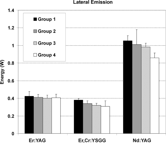 The emission profile of the coaxial guiding beam showed that the control honeycomb fiber tip (group 1) gave emissions along the length of the treated area (i.e., laterally) as well as in a forward direction. In the modified safe ended fibers in groups 2, 3, and 4, there were no visible lateral emissions from the terminal 2 mm of the fiber tips (Fig. 4 and Table 1). Fig. 4Emission profiles from optical fiber designs showing distribution of visible red light beam (632.8 or 635 nm). These examples show the Nd:YAG Bioletic fibers. Each radial division is 15 deg. The markings are at 1 mm intervals. (a) honeycomb fiber, showing an emission profile along the length of the fiber and in a forward direction. (b), (c), and (d) (group 2, 3, and 4, respectively) show no lateral emission from the terminal 2 mm of the fiber tips.  Table 1Emission profiles of various fiber tip designs. Data are shown for various fiber modifications, as follows: 1 = Emission seen in front of the modified tip; 2 = Emission seen along the length of the tip; 3 = Emission seen 2 mm back from the end of the fiber. Plain forward emitting fibers all showed emissions in the forward direction only.
Assessment of the emission profiles using thermal paper showed no detectable emission in the forward direction for all the safe ended tips, when the thermal paper was placed 2 mm in front of the tip (Table 1). The thermochromic dye assessment of thermal changes on the root surface showed that each tip design gave different patterns (Figs. 5 and 6). The plain [Figs. 5a and 6a] and conical fibers [Figs. 5b and 6b] gave large forward emissions with a well localized zone of elevated temperature on the root surface. The honeycomb fiber gave a broader zone more laterally along the length of the fiber [Figs. 5c and 6c]. The safe ended designs [Figs. 5d, 5e, 5f, 6d, 6e, 6f] showed minimal surface temperature change with emissions over the same broad area as the honeycomb fiber. Fig. 5Thermochromic dye study of diode laser-induced temperature changes on the root surface of a maxillary central incisor tooth, to explore changes in emission profiles between various tip designs. The tip was inserted to a depth of 5 mm into the canal in all cases. The greatest temperature change is indicated by blue and then green colors. Tip designs were as follows: (a) plain unmodified fiber; (b) conical fiber; (c) honeycomb fiber; (d) honeycomb fiber with a silver coated safe tip (group 2); (e) fiber with the apical 2 mm as a plain cone without abrasion and the distal portion in a honeycomb pattern (group 3); (f) fiber with the apical 2 mm not abraded but instead silver coated and the distal portion in a honeycomb pattern (group 4). Note the retrograde reflection of the visible red aiming beam from the canal orifice in panels (c)–(f), which occurs because of lateral emission from the tips. 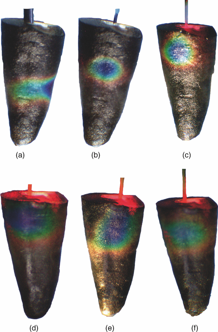 Fig. 6Thermochromic dye study with the tip was inserted to a depth of 5 mm short of the apex of the root. Tip designs are in the same sequence as in Fig. 5. 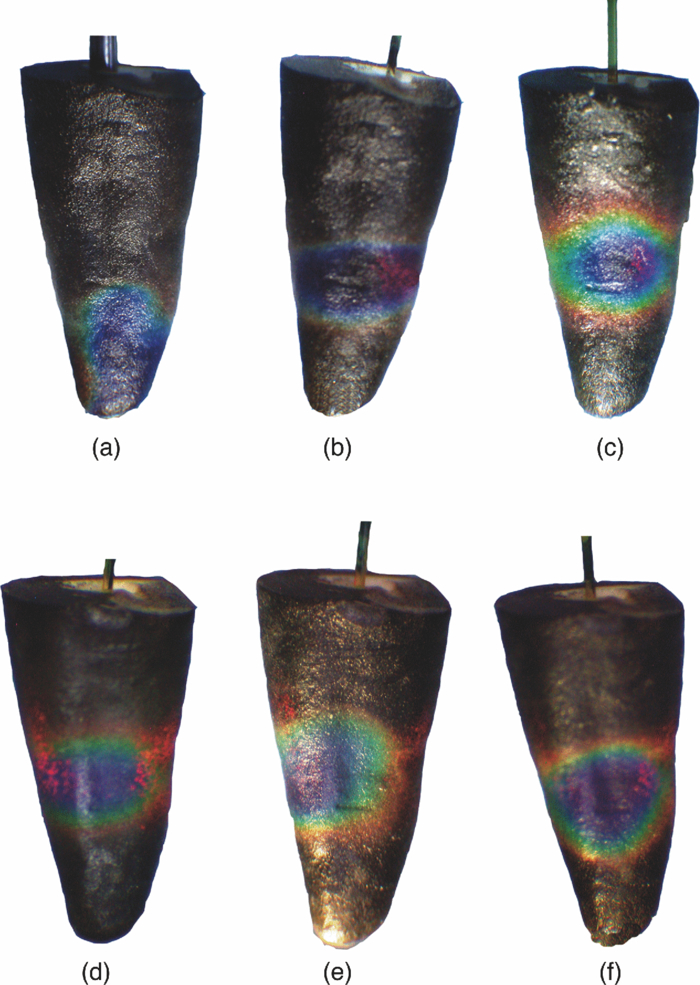 4.DiscussionFor some dental laser procedures, it is desirable to direct the exiting laser energy along an axis perpendicular to the longitudinal axis of the fiber, as well as along the length of the fiber tip, with little or no effect of the treatment beam in the forward direction. Conventional fiber tips are not effective in delivering laser energy laterally or perpendicular to the long axis of the fiber.22, 23 The limitations of both conical fiber designs15, 24, 25 and isotropic tips26 have led to interest in side firing tips. The present study extends previous work that described the fabrication and performance of a novel side firing (honeycomb) configuration for optical fiber tips.18 Because this honeycomb tip design gives both forward and lateral emissions, it was desirable in the present study to fabricate safe-ended variants of this, using silver plating to reduce emission of laser energy in the forward direction. This primarily occurs by internal reflection rather than by absorption, a point illustrated by the similar lateral emissions between coated and uncoated tips, and their similar thermal effects on teeth. The present results indicate that the safe-ended tip designs (groups 2–4) have considerably less laser output in the forward direction, in the order of 50%. Different tip configurations were achieved using the electroless plating technique, a method that gives uniform and smooth surface coatings of silver that have been shown to reflect infrared laser wavelengths.27, 28, 29 This method was found to be suitable for coating the external surface of fibers of various types. The emission patterns observed with teeth coated with thermochromic dye clearly show the different emission patterns of the modified tips with safe ends. It would be of value in root canal treatment for fiber tips to have the ability to irradiate the whole length of the root canal walls without having to manually move the fiber along the length of the root canal. Honeycomb fiber tips have the ability to emit laser energy along their length and hence may be a valuable tool for root canal disinfection and removal of debris. The present results indicate that silver coating attenuated forward emission from various tips. This effect should result in greater control of desirable laser effects (disinfection and debris removal) because coated tips will give less ablation in the forward direction and less generation of forward-moving shock waves. Fiber tips with safe ends would also suit procedures such as debridement of dental implants, where energy is laterally directed to remove dental plaque biofilm and calculus, rather than toward the supporting alveolar bone. Safe ended tips could also be suitable for certain vascular surgery or urology procedures where safe (nonend cutting) tips for fibers are necessary both to achieve the desired outcome and to reduce the likelihood of perforations. ReferencesA. Moritz and
U. Schoop,
“Lasers in endodontics,”
Oral Laser Application, 241
–313 Berlin, Quintessence
(2006). Google Scholar
R. George, I. A. Meyers, and
L. J. Walsh,
“Laser activation of endodontic irrigants using improved conical laser fiber tips for removing smear in the apical third of the root canal,”
J. Endod., 34
(12), 1524
–1527
(2008). https://doi.org/10.1016/j.joen.2008.08.029 Google Scholar
T. H. Van, T. M. John, and
E. G. Harold,
“Instruments, Materials, and Devices,”
Pathways of the Pulp, 233
–289 Mosby, St. Louis
(2006). Google Scholar
H. Jafarzadeh and
P. V. Abbott,
“Ledge formation: review of a great challenge in endodontics,”
J. Endod., 33
(10), 1155
–1162
(2007). https://doi.org/10.1016/j.joen.2007.07.015 Google Scholar
K. Jahan, M. Hossain, Y. Nakamura, Y. Yoshishige, J. I. Kinoshita, and
K. Matsumoto,
“An assessment following root canal preparation by Er,Cr:YSGG laser irradiation in straight and curved roots, in vitro,”
Lasers Med. Sci., 21
(4), 229
–234
(2006). https://doi.org/10.1007/s10103-006-0401-2 Google Scholar
D. Fried, N. Ashouri, T. Breunig, and
R. Shori,
“Mechanism of water augmentation during IR laser ablation of dental enamel,”
Lasers Surg. Med., 31
(3), 186
–193
(2002). https://doi.org/10.1002/lsm.10085 Google Scholar
S. R Visuri, H. A. Wigdor,
“Erbium laser ablation of dental hard tissue: effect of water cooling,”
Lasers Surg. Med., 18
(3), 294
–300
(1996). https://doi.org/10.1002/(SICI)1096-9101(1996)18:3<294::AID-LSM11>3.0.CO;2-6 Google Scholar
J. E. J. Burkes, J. Hoke, E. Gomes, and
M. Wolbarsht,
“Wet versus dry enamel ablation by Er:YAG laser,”
J. Prosthet. Dent., 67
(6), 847
–851
(1992). https://doi.org/10.1016/0022-3913(92)90599-6 Google Scholar
R. George and
L. J. Walsh,
“Factors influencing the ablative potential of the Er:YAG laser when used to ablate radicular dentine,”
J. Oral Laser. Appl., 8
(1), 33
–41
(2008). Google Scholar
Q. Q. Wang, C. F. Zhang, and
X. Z. Yin,
“Evaluation of the bactericidal effect of Er,Cr:YSGG, and Nd:YAG lasers in experimentally infected root canals,”
J. Endod., 33
(7), 830
–832
(2007). https://doi.org/10.1016/j.joen.2007.03.017 Google Scholar
U. Schoop, K. Goharkhay, J. Klimscha, M. Zagler, J. Wernisch, A. Georgopoulos, W. Sperr, and
A. Moritz,
“The use of the erbium, chromium:yttrium-scandium-gallium-garnet laser in endodontic treatment: the results of an in vitro study,”
J. Am. Dent. Assoc., 138
(7), 949
–955
(2007). Google Scholar
W. Gordon, V. A. Atabakhsh, F. Meza, A. Doms, R. Nissan, I. Rizoiu, and
R. H. Stevens,
“The antimicrobial efficacy of the erbium, chromium:yttrium-scandium-gallium-garnet laser with radial emitting tips on root canal dentin walls infected with Enterococcus faecalis,”
J. Am. Dent. Assoc., 38
(7), 992
–1002
(2007). Google Scholar
J. W. Blanken and
R. M. Verdaasdonk,
“Cavitation as a working mechanism of the Er,Cr:YSGG laser in endodontics: A visualization study,”
J. Oral Laser. Appl., 7
(2), 97
–106
(2007). Google Scholar
R. George and
L. J. Walsh,
“Apical extrusion of root canal irrigants when using Er:YAG and Er,Cr:YSGG lasers with optical fibers: an in vitro dye study,”
J. Endod., 34
(6), 706
–708
(2008). https://doi.org/10.1016/j.joen.2008.03.003 Google Scholar
P. R. Alves, N. Aranha, E. Alfredo, M. A. Marchesan,
A. Brugnera Junior, and
M. D. Sousa-Neto,
“Evaluation of hollow fiberoptic tips for the conduction of Er:YAG laser,”
Photomed. Laser Surg., 23
(4), 410
–415
(2005). https://doi.org/10.1089/pho.2005.23.410 Google Scholar
A. Stabholz, R. Zeltser, M. Sela, B. Peretz, J. Moshonov, D. Ziskind, and
A. Stabholz,
“The use of lasers in dentistry: principles of operation and clinical applications,”
Compend. Contin. Educ. Dent., 24
(12), 935
–948
(2003). Google Scholar
N. M. Fried and
A. K. Ngo,
“Side-firing germanium oxide optical fibers for delivery of Erbium:YAG laser radiation,”
J. Endourol, 20
(7), 475
–478
(2006). https://doi.org/10.1089/end.2006.20.475 Google Scholar
A. K. Ngo and
N. M. Fried,
“Delivery of erbium:YAG laser radiation through side-firing germanium oxide fibers,”
Proc. SPIE, 6083 60830O
(2006). https://doi.org/10.1117/12.659598 Google Scholar
M. Hmelar and
N. Manoukian,
“Side firing fiber optic laser probe,”
(1998). Google Scholar
R. George and
L. J. Walsh,
“Performance assessment of novel side firing flexible optical fibers for dental applications,”
Lasers Surg. Med., 41
(3), 214
–221
(2009). https://doi.org/10.1002/lsm.20747 Google Scholar
B. Schweig, Mirrors: A Guide to the Manufacture of Mirrors and Reflecting Surfaces, London, Pelham Books
(1973). Google Scholar
E. Altundasar, B. Ozcelik, Z. C. Cehreli, and
K. Matsumoto,
“Ultramorphological and histochemical changes after Er,Cr:YSGG laser irradiation and two different irrigation regimes,”
J. Endod., 32
(5), 465
–468
(2006). https://doi.org/10.1016/j.joen.2005.08.005 Google Scholar
I. Anic, S. Segovic, D. Katanec, K. Prskalo, and
D. Najzar-Fleger,
“Scanning electron microscopic study of dentin lased with argon, CO2, and Nd:YAG lasers,”
J. Endod., 24
(2), 77
–81
(1998). https://doi.org/10.1016/S0099-2399(98)80081-2 Google Scholar
S. Shoji, H. Hariu, and
H. Horiuchi,
“Canal enlargement by Er:YAG laser using a cone-shaped irradiation tip,”
J. Endod., 26
(8), 454
–458
(2000). https://doi.org/10.1097/00004770-200008000-00006 Google Scholar
M. Straßl, B. Üblacker, A. Bäcker, F. Beer, A. Moritz, and
E. Wintner,
“Comparison of the emission characteristics of three erbium laser systems — A physical case report,”
J. Oral Laser. Appl., 4
(4), 263
–270
(2004). Google Scholar
E. J. Hutson,
“The development of radio-opaque, isotropic, fibre-optic probes for light dosimetry studies in photodynamic therapy,”
Phys. Med. Biol., 38 1529
–1536
(1993). https://doi.org/10.1088/0031-9155/38/10/013 Google Scholar
J. A. Harrington,
“A review of IR transmitting, hollow waveguides,”
Fiber. Integr. Opt., 19 211
–227
(2000). https://doi.org/10.1080/01468030050058794 Google Scholar
M. Ben-David, N. I. Croitoru, A. Inberg, G. Revsin, I. Gannot, and
I. Gannot,
“Electroless deposited broadband omnidirectional multilayer reflectors for mid-infrared lasers,”
Proc. SPIE, 4616 97
–104
(2002). https://doi.org/10.1117/12.463801 Google Scholar
A. Hongo, M. Miyagi, Y. Kato, M. Suzumura, S. Kubota, Y. Wang, T. Shimomura, A. Katzir, and
A. H. James,
“Fabrication of dielectric-coated silver hollow glass waveguides for the infrared by liquid-flow coating method,”
Proc. SPIE, 2677 55
–63
(1996). https://doi.org/10.1117/12.237566 Google Scholar
|
||||||||||||||||||||||||||||||||||||||||||||||||||||||||||||


