
|
|
1.IntroductionOptical coherence tomography (OCT) is a noncontact, noninvasive optical technique allowing micrometer resolution imaging of tissues.1 The recently developed Fourier-domain OCT (FD-OCT) has attracted considerable attention due to the advantages over conventional time-domain OCT (TD-OCT) in terms of A-scan speed and detection sensitivity.2, 3, 4 FD-OCT records the spectrum of the interference signal either simultaneously with a broadband light source and a spectrometer (spectral domain OCT) or sequentially with a high-speed swept laser source and a single detector (swept source OCT, SS-OCT).5, 6 One-dimensional in-depth reflectivity profile (A-scan) can be determined by Fourier transform of the acquired spectral interferogram. However, Fourier transform of the sampled real-valued data introduces complex conjugate ambiguity and hence the mirror image. In practice, the measured sample has to be positioned at one side of the zero optical path length difference (OPD) position to avoid overlapping of mirror images,5 which is referred to as the conventional sample position shift approach in this paper. With this approach only half of the depth range is available for OCT imaging, and noticeable sensitivity degradation will occur with increasing OPD between reference arm and sample arm. To restore the full depth range for OCT imaging, many approaches have been proposed to resolve complex conjugate ambiguity. A phase-shifting method was used to reconstruct the complex interferogram, but polychromatic phase error and phase shift error can introduce unsuppressed artifacts.7 As extensions of the phase-shifting method, spatial phase modulation methods8, 9 were presented, where phase-shifting and transverse-scanning were performed simultaneously for an increase of the imaging speed. Simultaneous detection of the real and imaginary parts of the complex interferogram was proposed either through a 3 ×3 fiber coupler10 or polarization-based optical demodulation11 However, a wavelength dependent splitting ratio of the coupler or birefringence of the sample contributes undesirable artifacts. A dispersion-encoded method based on an iterative algorithm was proposed to obtain full-range imaging,12 and later a fast version of the iterative algorithm was demonstrated to improve the method.13 A carrier frequency approach based on an electro-optic phase modulator14 and an acousto-optic frequency shifter15, 16 was previously reported to realize full-range SS-OCT imaging. However, implementation of such approaches in a high-speed SS-OCT system is difficult because the required carrier frequency should be increased proportionally to the sweeping rate of the laser source. A grating-based rapid scanning optical delay line has been widely implemented in TD-OCT.17, 18 We first put forward the idea of full-range imaging in FD-OCT by carrier frequency based on transmissive dispersive optical delay line (TDODL) in a pending Chinese patent.19 Later it comes to our attention that an essentially similar method is presented by Dhalla,20 where a reflective dispersive optical delay line (RDODL) is used. However, a wave-number dependent instantaneous group delay and its effect on the spectral interference signal are not considered. In this paper, we present the method and result of introducing carrier frequency by a TDODL to realize full-range FD-OCT imaging. For a complete description of the proposed method, the instantaneous coherence function is introduced in derivation of the spectral interference signal. Measured envelopes of the spectral interference signal are presented for both the TDODL method and the conventional sample position shift approach. Implementation of the proposed method for full-range imaging is conducted in a custom-built SS-OCT system. 2.MethodBecause the additional phase introduced by the proposed TDODL is equivalent to that by a RDODL, and the light path in a RDODL can be clearer demonstrated from the top view, the carrier frequency in the wave-number domain introduced by a RDODL is conceptually illustrated in Fig. 1a. A typical RDODL is comprised of a collimator (C), a four times-pass diffraction grating (G), a Fourier lens (L), a reflective mirror (M1) with tilt angle of γ, and a double-pass mirror (M2). A conventional sample position shift approach realized by shifting the reference mirror for one-side offset sample position relative to the reference arm is also depicted for comparison. A simplified reference arm comprised of a collimator (C) and a reference mirror (M) is shown in Fig. 1c. The zoomed view related to the red dashed rectangle in Fig. 1a is shown in Fig. 1b. Fig. 1Carrier frequency introduced by a RDODL (a) with zoomed view, (b) of the dashed zone in (a), and conventional sample position shift method (c). 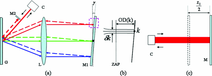 We define three different wave-numbers in the interference signal expression. k 0 is defined as the center wave-number of the whole sweep range of the swept source. k is the instantaneous center wave-number of the spectral linewidth, and κ is the wave-number within the instantaneous spectral linewidth. δk is defined as the spectral bandwidth of the instantaneous laser output. Under the small angle approximation, the optical delay (OD) as depicted in Fig. 1b corresponding to an instantaneous center wave-number with the zero tilt angle plane as the reference plane due to the tilted mirror in RDODL is expressed by16, 17 Eq. 1[TeX:] \documentclass[12pt]{minimal}\begin{document}\begin{equation} {\rm OD}(k) \approx \frac{{2\pi \gamma f(k_0 - k)}}{{pkk_0 }}, \end{equation}\end{document}Generally, the spectral resolution of the dispersive optical delay line (DODL) is less than the instantaneous linewidth of the swept source. The grating in the DODL cannot disperse the instantaneous spectral linewidth into finer spectrum. Therefore, the phase corresponding to any wave-number within an instantaneous linewidth is given by Eq. 2 disregarding the tilting status of the mirror Eq. 2[TeX:] \documentclass[12pt]{minimal}\begin{document}\begin{equation} \phi (\kappa) = \kappa \cdot \Delta z + \kappa \frac{{8\pi \gamma f(k - k_0)}}{{pkk_0 }}, \end{equation}\end{document}The spectral interference signal due to light from the reference arm, E R, and the sample arm, E S, can be expressed as Eq. 3[TeX:] \documentclass[12pt]{minimal}\begin{document}\begin{eqnarray} I(k) &=& \int_{ - \infty }^{ + \infty } {{\it {real}}\left\{ {\int_{k - \frac{{\delta k}}{2}}^{k + \frac{{\delta k}}{2}} {E_S (\kappa) \cdot E_R^* (\kappa)d\kappa } } \right\}d\Delta z}\nonumber\\ &=& \int_{ - \infty }^\infty {S(k) \cdot \int_{k - \frac{{\delta k}}{2}}^{k + \frac{{\delta k}}{2}} {\sqrt {R_S (\Delta z)} \cdot \sqrt {R_R } \cdot \cos [\phi (\kappa)]d\kappa } d\Delta z}.\nonumber\\ \end{eqnarray}\end{document}4.Eq. 4a[TeX:] \documentclass[12pt]{minimal}\begin{document}\begin{eqnarray} I(k) &=& S(k)\sqrt {R_R } \cdot \int_{ - \infty }^{ + \infty } {\sqrt {R_S (\Delta z)} } \left| {\Gamma [{\rm GOD}_{\delta k} (k),\delta k]} \right|\nonumber\\ &&\times\cos \left[ {k\left({\Delta z + \frac{{8\pi \gamma f}}{{p \cdot k_0 }}} \right) - \frac{{8\pi \gamma f}}{p} + \phi (\Delta z)} \right]d\Delta z,\nonumber\\ \end{eqnarray}\end{document}Eq. 4b[TeX:] \documentclass[12pt]{minimal}\begin{document}\begin{equation} \left| {\Gamma [{\rm {GOD}}_{\delta k} (k),\delta k]} \right| = \exp \left[ { - \left({\frac{{\delta k \cdot {\rm {GOD}}_{\delta k} (k)}}{{4\sqrt {\ln 2} }}} \right)^2 } \right]. \end{equation}\end{document}Eq. 5[TeX:] \documentclass[12pt]{minimal}\begin{document}\begin{equation} z_0 = - \frac{{8\pi \gamma f}}{{p \cdot k_0 }}. \end{equation}\end{document}Based on Eq. 2, the instantaneous phase optical delay (POD) and instantaneous group optical delay (GOD) are given by Eq. 6[TeX:] \documentclass[12pt]{minimal}\begin{document}\begin{equation} {\rm POD}_{\delta k} (k) = \frac{{\phi (k)}}{k} = \Delta z + \frac{{8\pi \gamma f(k_0 - k)}}{{p \cdot k_0 \cdot k}}, \end{equation}\end{document}Eq. 7[TeX:] \documentclass[12pt]{minimal}\begin{document}\begin{equation} {\rm GOD}_{\delta k} (k) = \frac{{\partial \phi (\kappa)}}{{\partial \kappa }}\left| {_{\kappa = k} } \right. = \Delta z + \frac{{8\pi \gamma f(k_0 - k)}}{{p \cdot k_0 \cdot k}}. \end{equation}\end{document}Eq. 8[TeX:] \documentclass[12pt]{minimal}\begin{document}\begin{eqnarray} I(k) &=& S(k) \cdot \sqrt {R_R } \cdot \int_{ - \infty }^\infty \sqrt {R_S (\Delta z)} \cdot \left| {\Gamma [{\rm GOD}_{\delta k} (k),\delta k]} \right|\nonumber\\ && \cdot \cos [k \cdot {\rm POD}_{\delta k} (k) + \phi (\Delta z)]d\Delta z. \end{eqnarray}\end{document}We define the group delay corresponding to the whole sweeping range Δk of the swept source introduced by the DODL as the full-bandwidth group delay which is expressed by17, 19 Eq. 9[TeX:] \documentclass[12pt]{minimal}\begin{document}\begin{equation} {\rm GOD}_{\Delta k} = - \frac{{8\pi \gamma f}}{{p \cdot k_0 }} = z_0. \end{equation}\end{document}Eq. 10[TeX:] \documentclass[12pt]{minimal}\begin{document}\begin{eqnarray} I(k) &=& S(k)\sqrt {R_R } \cdot \int_{ - \infty }^{ + \infty } {\sqrt {R_S (\Delta z)} } \left| {\Gamma ({\rm GOD}_{\delta k} (k),\delta k)} \right|\nonumber\\ &&\times\cos \left[ {k(\Delta z - {\rm GOD}_{\Delta k}) - \frac{{8\pi \gamma f}}{p} + \phi (\Delta z)} \right]d\Delta z.\nonumber\\ \end{eqnarray}\end{document}3.Experiments and ResultsFigure 2a shows schematic of our SS-OCT system capable of full-range imaging based on the proposed method. The swept laser source (HSL-2000, Santec Inc.) with sweeping range of 100 nm and center wavelength of 1320 nm is operated at 20 KHz. 90% of the output power from the swept laser source is fed into a customized imaging interferometer, and the rest, 10%, is sent into the calibration interferometer (INT-MZI-1300, Thorlabs, Inc.) to generate the calibration signal. The imaging interferometer is constructed as a Mach–Zehnder-type interferometer with 90% of the light into the sample arm and 10% into the reference arm. Light returned from the sample arm and reference arm is combined at a 50/50 fiber coupler and then detected by a balanced photodiode (Model-1817, New Focus Inc.). Both imaging signal and calibration signal are digitized simultaneously by the DAQ card (PCI-5122, National Instrument Inc.). A spectral phase-based wave-number domain interpolation method is applied for uniform wave-number sampling of the spectral interference signal in the experiment.23 Sufficient sampling of the OCT imaging signal with a uniform wave-number interval are directly interpolated in the wave-number domain based on the spectral phase derived from the MZI calibration signal, which will construct the depth profile without an aliasing artifact. A double-pass TDODL with details shown in Fig. 2b is implemented in the reference arm to generate carrier frequency in wave-number domain. The difference of the custom-built double-pass TDODL relative to the double-pass RDODL is the right-angle prism (P) instead of a plane mirror adopted for double passing. The right-angle prism is used to separate the incoming light and the output light along the direction normal to the dispersive direction of the grating. The focus length of the Fourier lens is 75 mm and the grating constant is 235.8 lines/mm. The introduced phase delay and group delay by TDODL remains the same value with those given by Eqs. 6, 7, respectively. Fig. 2(a) Schematic of the custom-built high-speed SS-OCT system capable of full-range imaging based on carrier frequency introduced by TDODL and (b) layout of the TDODL.  As described in Eq. 8, both power spectral density and instantaneous coherence function modulates the envelope of the spectral interference signal, which is related to the axial resolution and sensitivity of the reconstructed axial profile. To investigate the effect of instantaneous group delay on the signal, envelopes of the spectral interference signal corresponding to different distance-shifts (DS) introduced by TDODL and reference mirror-shift were measured. In both cases a reflective mirror positioned at a fixed depth Δz around 0.5 mm is taken as the sample. In the conventional method different DSs are realized by shifting the reference mirror at different positions, while in the proposed method different DSs are realized by different tilt angles in TDODL. The introduced distance-shift in both methods is increased with step of 0.25 mm. The envelopes are obtained by bandpass filtering and twice Fourier transform of the recorded spectral interference signal. The envelopes corresponding to 10 DSs are illustrated in Fig. 3. As demonstrated in Fig. 3a, envelopes of the spectral interference signal at all DSs are mainly determined by the power spectral density with no evident degradation by the instantaneous coherence function due to a small instantaneous group delay. However, in a conventional sample position shift approach noticeable degradation of envelopes are observed for larger DS as shown in Fig. 3b. Three typical envelopes corresponding to DSs of 0.5, 1.5, and 2.5 mm are demonstrated in Figs. 3c, 3d for the TDODL method and conventional method, respectively. In consideration of the coupling efficiency of TDODL corresponding to different tilt angles, the power of the envelopes shown in Fig. 3c decreased somewhat with a larger tilt angle. From a comparison of Figs. 3c, 3d, it is obvious that the proposed method is advantageous than the conventional sample position shift approach in terms of sensitivity fall-off. The experimental results confirm the validity of the developed theory on the spectral interference signal expressed by Eq. 10. Fig. 3Envelopes of spectral interference signal at different distance-shifts introduced by TDODL (a) and conventional approach (b). Three envelopes fetched from (a) and (b) for comparison shown in (c) and (d). 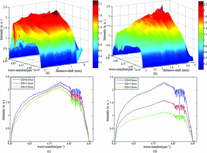 To characterize the sensitivity performance of the full-range SS-OCT system based on the proposed method, the spectral interference signal obtained with conventional sample position shift approach and TDODL-based method was measured and compared. For the proposed TDODL-based method, the tilt angle γ in the TDODL was set to be 1.6 deg and a DS of 2.6 mm was achieved. By varying the axial positions of a mirror sample placed in the sample arm, the point spread functions corresponding to different axial depths were measured for both methods. In the A-scan signals acquired with conventional sample position shift approach shown in Fig. 4a, the complex conjugate ambiguity artifacts are clearly shown. At zero optical path length difference (ZPD) a strong dc peak from the unbalanced detected spectral noninterference signal is also present. As shown in Fig. 4b, the A-scan signal at ZPD is carried up to the axial position of 2.6 mm where the highest sensitivity appears, and the point spread functions at the other axial positions are centered about the position of 2.6 mm. The obtained spectral interference signals were processed with Heaviside windowing and bandpass filtering which make the complex conjugate ambiguity and spectral artifact located at dc suppressed to the background noise level as shown in Fig. 4b. Fig. 4(a) Point spread functions measured at different axial positions with the conventional sample position shift approach and (b) TDODL-based full-range imaging method.  In order to evaluate the performance of our system for full-range imaging, we acquired in vivo images of anterior segment of the fish eye. Figure 5 demonstrates the reconstructed cross-sectional images of the same sample by different methods. The image size is about 3 mm×5 mm which is formed by 600 A-lines. Figures 5a, 5b, 5c have the same dynamics range and color map. It can be seen that overlapping mirror images as well as dc and autocorrelation terms severely obscure the actual sample structure by standard SS-OCT as shown in Fig. 5a. Mirror image, dc term, and autocorrelation term are almost suppressed by the proposed method as shown in Fig. 5b. The complex conjugate artifact-separated OCT image shown in Fig. 5c is obtained by a conventional sample position shift approach, and the sensitivity is degraded a lot due to the large instantaneous group delay. Fig. 5In vivo SS-OCT images of anterior segment of a fish eye. (a) Overlapping of mirror images without group delay, (b) mirror-free imaging obtained by TDODL-based method, (c) separation of mirror images with one-side offset realized by conventional approach.  The mirror-image suppression capability of the custom-built full-range SS-OCT system is calibrated with a partial reflector placed at a position corresponding to the depth of 490 μm. Figure 6 presents two reconstructed depth profiles with and without carrier frequency introduced by TDODL, which suggests that total suppression of a complex conjugate image artifact is achieved. 4.ConclusionIn summary, we have developed a high-speed SS-OCT system capable of full-range imaging. A TDODL is implemented in the reference arm to generate high carrier frequency in wave-number domain. Most important, in recognition of the instantaneous spectral linewidth of the swept laser source, both instantaneous phase and group optical delays introduced by TDODL are considered in the spectral interference signal. Minimized sensitivity fall-off up to an equivalent distance shift of 3 mm is confirmed by envelope measurement of the spectral interference signal. Mirror image, as well as dc and autocorrelation terms, are suppressed to a background level. The feasibility of the established system is evaluated by in vivo imaging of the anterior segment of a fish eye. AcknowledgmentsThis work was supported by National High Technology Research and Development Program of China (Grant No. 2006AA02Z4E0) and Natural Science Foundation of China (Grant Nos. 60978037 and 60878057). ReferencesD. Huang,
E. A. Swanson,
C. P. Lin,
J. S. Schuman,
W. G. Stinson,
W. Chang,
M. R. Hee,
T. Flotte,
K. Gregory,
C. A. Puliafito, and
J. G. Fujimoto,
“Optical coherence tomography,”
Science, 254
(5035), 1178
–1181
(1991). https://doi.org/10.1126/science.1957169 Google Scholar
M. Choma,
M. Sarunic,
C. Yang, and
J. Izatt,
“Sensitivity advantage of swept source and Fourier domain optical coherence tomography,”
Opt. Express, 11
(18), 2183
–2189
(2003). https://doi.org/10.1364/OE.11.002183 Google Scholar
R. Leitgeb,
C. Hitzenberger, and
A. Fercher,
“Performance of fourier domain vs. time domain optical coherence tomography,”
Opt. Express, 11
(8), 889
–894
(2003). https://doi.org/10.1364/OE.11.000889 Google Scholar
J. F. de Boer,
B. Cense,
B. H. Park,
M. C. Pierce,
G. J. Tearney, and
B. E. Bouma,
“Improved signal-to-noise ratio in spectral-domain compared with time-domain optical coherence tomography,”
Opt. Lett., 28
(21), 2067
–2069
(2003). https://doi.org/10.1364/OL.28.002067 Google Scholar
Y. Yasuno,
V. D. Madjarova,
S. Makita,
M. Akiba,
A. Morosawa,
C. Chong,
T. Sakai,
K. Chan,
M. Itoh, and
T. Yatagai,
“Three-dimensional and high-speed swept-source optical coherence tomography for in vivo investigation of human anterior eye segments,”
Opt. Express, 13
(26), 10652
–10664
(2005). https://doi.org/10.1364/OPEX.13.010652 Google Scholar
M. Wojtkowski,
T. Bajraszewski,
P. Targowski, and
A. Kowalczyk,
“Real-time in vivo imaging by high-speed spectral optical coherence tomography,”
Opt. Lett., 28
(19), 1745
–1747
(2003). https://doi.org/10.1364/OL.28.001745 Google Scholar
M. Wojtkowski,
A. Kowalczyk,
R. Leitgeb, and
A. F. Fercher,
“Full range complex spectral optical coherence tomography technique in eye imaging,”
Opt. Lett., 27
(16), 1415
–1417
(2002). https://doi.org/10.1364/OL.27.001415 Google Scholar
Y. Yasuno,
S. Makita,
T. Endo,
G. Aoki,
M. Itoh, and
T. Yatagai,
“Simultaneous B-M-mode scanning method for real-time full-range Fourier domain optical coherence tomography,”
Appl. Opt., 45
(8), 1861
–1865
(2006). https://doi.org/10.1364/AO.45.001861 Google Scholar
K. Wang,
Z. Ding,
Y. Zeng,
J. Meng, and
M. Chen,
“Sinusoidal B-M method based spectral domain optical coherence tomography for the elimination of complex-conjugate artifact,”
Opt. Express, 17
(19), 16820
–16833
(2009). https://doi.org/10.1364/OE.17.016820 Google Scholar
M. A. Choma,
C. Yang, and
J. A. Izatt,
“Instantaneous quadrature low-coherence interferometry with 3 × 3 fiber-optic couplers,”
Opt. Lett., 28
(22), 2162
–2164
(2003). https://doi.org/10.1364/OL.28.002162 Google Scholar
B. J. Vakoc,
S. H. Yun, and
G. J. Tearney,
“Elimination of depth degeneracy in optical frequency-domain imaging through polarization-based optical demodulation,”
Opt. Lett., 31
(3), 362
–364
(2006). https://doi.org/10.1364/OL.31.000362 Google Scholar
B. Hofer,
B. Považay,
B. Hermann,
A. Unterhuber,
G. Matz, and
W. Drexler,
“Dispersion encoded full range frequency domain optical coherence tomography,”
Opt. Express, 17
(1), 7
–24
(2009). https://doi.org/10.1364/OE.17.000007 Google Scholar
B. Hofer,
B. Považay,
A. Unterhuber,
L. Wang,
B. Hermann,
S. Rey,
G. Matz, and
W. Drexler,
“Fast dispersion encoded full range optical coherence tomography for retinal imaging at 800 nm and 1060 nm,”
Opt. Express, 18 4898
–4919
(2010). https://doi.org/10.1364/OE.18.004898 Google Scholar
J. Zhang,
J. S. Nelson, and
Z. Chen,
“Removal of a mirror image and enhancement of the signal-to-noise ratio in Fourier-domain optical coherence tomography using an electro-optic phase modulator,”
Opt. Lett., 30
(2), 147
–149
(2005). https://doi.org/10.1364/OL.30.000147 Google Scholar
S. Yun,
G. Tearney,
J. de Boer, and
B. Bouma,
“Removing the depth-degeneracy in optical frequency domain imaging with frequency shifting,”
Opt. Express, 12
(20), 4822
–4828
(2004). https://doi.org/10.1364/OPEX.12.004822 Google Scholar
M. Davis,
M. A. Choma, and
J. A. Izatt,
“Heterodyne swept-source optical coherence tomography for complete complex conjugate ambiguity removal,”
J. Biomed. Opt., 10
(6), 064005
(2005). https://doi.org/10.1117/1.2136147 Google Scholar
G. J. Tearney,
B. E. Bouma, and
J. G. Fujimoto,
“High-speed phase- and group-delay scanning with a grating-based phase control delay line,”
Opt. Lett., 22
(23), 1811
–1813
(1997). https://doi.org/10.1364/OL.22.001811 Google Scholar
A. Rollins,
S. Yazdanfar,
M. Kulkarni,
R. Ung-Arunyawee, and
J. Izatt,
“In vivo video rate optical coherence tomography,”
Opt. Express, 3
(6), 219
–229
(1998). https://doi.org/10.1364/OE.3.000219 Google Scholar
T. Wu,
Z. Ding,
M. Chen,
C. Wang,
L. Wang,
Y. Tao, and
B. Wang,
“Method and system of mirror image separation based on group delay induced wave-number carrier frequency,”
(2010) http://www.sipo.gov.cn/ Google Scholar
A. Dhalla and
J. A. Izatt,
“Complete complex conjugate resolved heterodyne swept-source optical coherence tomography using a dispersive optical delay line,”
Biomed. Opt. Express, 2
(5), 1218
–1232
(2011). https://doi.org/10.1364/BOE.2.001218 Google Scholar
S. Yun,
G. Tearney,
J. de Boer,
N. Iftimia, and
B. Bouma,
“High-speed optical frequency-domain imaging,”
Opt. Express, 11 2953
–2963
(2003). https://doi.org/10.1364/OE.11.002953 Google Scholar
T. von Niederhäusern,
C. Meier,
M. Duelk, and
P. Vorreau,
“Instantaneous coherence length measurement of a swept laser source using a Mach-Zehnder interferometer,”
Proc. SPIE, 7889 78892R
(2011). https://doi.org/10.1117/12.873769 Google Scholar
T. Wu,
Z. Ding,
L. Wang, and
M. Chen,
“Spectral phase based k-domain interpolation for uniform sampling in swept-source optical coherence tomography,”
Opt. Express, 19 18430
–18439
(2011). https://doi.org/10.1364/OE.19.018430 Google Scholar
|


