

|
|
1.IntroductionThe Monte Carlo (MC) technique is a powerful approach for modeling of light transport in strongly scattering biological tissues. The resulting energy deposition maps can be used in numerical simulations of heat transport and consequent physiological effects in various tissues and organs. In order to obtain realistic results and trustable predictions, however, one must apply appropriate optical parameters and a representative model of the lesion geometry. Several earlier studies have extended the multilayer MC model developed by Wang 1 to three dimensions.2, 3, 4 This has enabled treatment of skin inclusions with arbitrary shapes irradiated with spatially confined laser beams. Herein, we present and test an augmented MC model of laser-irradiated human skin, with special attention devoted to treatment of side boundaries of the spatially discretized volume of interest (VOI). In earlier documented three-dimensional (3D) MC models, either a perfectly reflecting (mirror) or escape boundary condition (BC) was applied at the VOI's side surfaces. Rigorously speaking, however, the first approach implies an infinitely wide irradiation beam and periodically distributed skin structures, while the second is suitable only for treatment of entire organs surrounded by air. For all other cases, a common solution to prevent edge-related artifacts from affecting the results is to move the VOI side boundaries (usually of the escape type) sufficiently far from the investigated structure. However, this approach may become prohibitively time- and memory consuming when studying the response of small absorbing inclusions, requiring fine discretization of the VOI, to irradiation with significantly larger, yet still finite and not necessarily homogeneous laser beams. One relevant example is port wine stain (PWS) lesions, with blood vessel diameters ranging from 20 to 300 μm, which are routinely treated with lasers beams with a diameter of 5 mm or more. To overcome this problem, we have developed an alternative approach, called “extended layers.” Outside of the voxelized VOI, model photons are propagated in laterally infinite tissue layers, but without recording the local energy deposition. This idea was introduced in the 3D MC optical model by Barton,4 but only at the VOI bottom boundary, thus extending the optical properties of dermis to the semi-infinite column of tissue below the VOI. As we demonstrate in the following, extending the same principle to the lateral dimensions offers great advantages in terms of modeling flexibility, accuracy, and/or computational demands, depending on which of the former approaches is used for the purpose of comparison. After discussing the model geometry and selection of tissue optical properties, we present first our predictions of diffuse reflectance of skin at wavelengths of 532, 585, and 595 nm, which are most commonly used for treatment of cutaneous vascular lesions. Three epidermal melanin concentrations are considered, representing Caucasian, Asian, and African skin. Next, we analyze the differences between the MC simulation results as obtained by using the two boundary conditions mentioned above and our extended layers approach, for irradiation of one or two blood vessels in human skin with a 1-mm diameter laser beam. Finally, we simulate laser treatment of PWS lesions by means of selective photothermolysis.5 To this end, we complement our MC optical model by numerical modeling of thermal transport and tissue-specific coagulation kinetics. Radiant exposure thresholds for complete photocoagulation of a typical PWS blood vessel, as well as for onset of epidermal thermal damage, are computed for different combinations of laser wavelength and skin phototype, with and without application of cryogen spray (CS) cooling,6 and correlated with values from some clinical reports. Namely, despite the unquestionable enhancement of PWS treatment efficacy and safety offered by CS cooling, the risk of permanent epidermal injury still limits the applicable radiant exposure to levels inadequate for permanent PWS vessel coagulation in many patients, especially those with darker skin phototypes. Development of sufficiently detailed and realistic numerical models of PWS response to laser irradiation should facilitate preliminary testing of novel treatment strategies with the potential to allow safe and effective treatment for a larger number of PWS patients. 2.Methodology2.1.Optical Transport ModelOur simulation of light transport in PWS skin is based on the well-established weighted-photon MC technique.1 In this approach, a large number of energy packets (“photons”) propagate through the tissue and deposit a fraction of their energy into specific volume elements, according to the local absorption properties. Stochastic relations are used to determine each photon's random trajectory, according to physical laws of light scattering, reflection, and refraction. Specifics of these relations depend on optical properties, i.e., absorption coefficient (μ a), scattering coefficient (μ s), anisotropy (g), and index of refraction (n) of the involved tissues. With an increasing number of simulated photons and ever finer spatial discretization of the treated volume, the resulting energy deposition map ideally converges toward the correct spatial distribution of the absorbed light energy. Extending the multilayer MC model1 to three dimensions allows treatment of skin inclusions of arbitrary complex shape and optical heterogeneity. In the presented examples, the VOI has dimensions of 1 × 1 mm2 in the plane parallel to the skin surface (coordinates x and y) and 1.5 mm in depth (z). The spatial discretization step is 2 × 2 μm2 in the (x, z) plane and 20 μm in the y direction, resulting in a 3D grid with 500×50×750 voxels. A special care is devoted to realistic treatment of the VOI side boundaries. As indicated above, neither mirror, nor escape BC is suitable for high-resolution treatment of relatively small volumes in human skin, irradiated with spatially confined laser beams. In our approach, named extended layers, photons are launched according to the laser beam intensity profile and propagated in laterally infinite tissue layers until they deposit all their energy or escape into the air. Optical properties of these layers are inherited from the border VOI elements at the respective depths, and the majority rules whenever not all of them represent the same tissue. Perhaps most importantly, energy deposition is computed and recorded only within the VOI, which keeps memory requirements at a manageable level and greatly reduces the computation time. The same principle is applied also at the bottom boundary of the VOI. Specifically, the entire semi-space below the VOI bottom boundary inherits the optical properties from the lowest VOI layer, which is occupied by adipose in all presented examples. The MC code is implemented in Visual C++ (Visual Studio 2008, Microsoft, Redmond, Washington). Utilization of multiple threads helps speed up the computation. 2.2.Skin Model Geometry and Optical ParametersOur basic skin model is composed of three layers, which represent the epidermis (thickness: 60 μm), dermis (1.5 mm), and a semi-infinite layer of subcutis. Melanin is assumed to be homogeneously distributed within the epidermis. The effective fractional content of melanin (f mel) is calculated from absorption coefficient at 694 nm (μ a ,epi) as determined from diffuse reflectance measurements by Svaasand 7 To this end, we use the well-known relations:8 Eq. 1a[TeX:] \documentclass[12pt]{minimal}\begin{document}\begin{equation} \mu _{a{\rm,epi}} = f_{{\rm mel}} \mu _{a{\rm,mel}} + \left({1 - f_{{\rm mel}} } \right)\mu _{a{\rm,base}},\end{equation}\vspace*{-8pt}\end{document}Eq. 1b[TeX:] \documentclass[12pt]{minimal}\begin{document}\begin{equation} \mu _{a{\rm,mel}} = 6.6 \cdot 10^{10} \,{\rm mm}^{ - 1} \,\left({\frac{\lambda }{{{\rm nm}}}} \right)^{ - 3.33},\end{equation}\vspace*{-8pt}\end{document}Eq. 1c[TeX:] \documentclass[12pt]{minimal}\begin{document}\begin{equation} \mu _{a{\rm,base}} = 0.0244\,{\rm mm}^{ - 1} + 8.53\,{\rm mm}^{ - 1} \,\exp \left({ - \frac{{\lambda - 154\,{\rm nm}}}{{66.2\,{\rm nm}}}} \right),\end{equation}\end{document}The resulting melanin fractional contents for fair Caucasian, moderately pigmented Middle Eastern or Asian, and African skin are f mel = 1.3%, 3.5%, and 9%, respectively. The corresponding epidermal absorption coefficients at 532, 585, and 595 nm, obtained by using the wavelength dependence relations (1), are collected in Table 1. Table 1Epidermal absorption coefficients at three common laser wavelengths, representative of three skin phototypes.
For blood, we assume a hematocrit of 40% and oxygen saturation of 70%. The absorption coefficients at three considered wavelengths are obtained by linear interpolation of the values for oxygenated and deoxygenated whole blood as reported by Meinke 9 (see Table 2). The absorption coefficients of subcutis (adipose) are from Bashkatov 10 Table 2Absorption coefficient (μ a), scattering coefficient (μ s), anisotropy coefficient (g), and refractive index (n) values used in our MC model of optical transport in skin.
A wide range of scattering parameter values for constituents of human skin can be found in the literature. We have tested several combinations of the reported values in MC simulations of both normal (assumed 1% blood in dermis) and PWS skin. For this study, we have selected those values of μ s and g from recent reports, which resulted in good agreement between the predicted diffuse reflectance and reported experimental values. The value of μ s for adipose was calculated from the reduced scattering coefficient ( [TeX:] $\mu_{s}^{\prime}$ ) as measured by Baskhatov,10 and the anisotropy coefficient (g) from Flock 11 For our analysis of blood photocoagulation in laser therapy of PWS, we include one blood vessel with diameter d = 150 μm and a horizontal axis 400 μm below the skin surface (Fig. 1). Fig. 1Cross-sectional view of our PWS model geometry, including the epidermal layer (dark gray), six dermal layers with different absorption properties (gray), one horizontal blood vessel (white), and a semi-infinite adipose layer underneath. Dashed lines delineate the VOI. 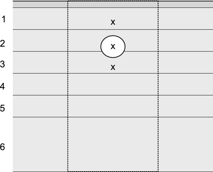 In order to account for optical shading by other, not explicitly modeled PWS vessels,12 the dermis is divided into five 0.2-mm thick layers and one layer with a thickness of 0.5 mm. The corresponding absorption coefficients μ a,i (Table 3) are calculated by considering the reported fractional contents of blood (f i) in each layer:13 Eq. 2[TeX:] \documentclass[12pt]{minimal}\begin{document}\begin{equation} \mu _{{\rm a,}i} = f_i \,C_i \,\mu _{{\rm a,bld}} + \left({1 - f_i } \right)\mu _{{\rm a,der}}. \end{equation}\end{document}Eq. 3[TeX:] \documentclass[12pt]{minimal}\begin{document}\begin{eqnarray} C_i &=& \,\,0.03895 + \,\,0.48588\,\,\exp \left({ - \frac{{\mu _{{\rm a,bld}} \,r_i }}{{0.1928}}} \right)\nonumber\\ && + \, 0.46803\,\,\exp \left({ - \frac{{\mu _{{\rm a,bld}} \,r_i }}{{0.91443}}} \right).\end{eqnarray}\end{document}Table 3Mean blood vessel radii (r i), fractional blood contents (f i) (Ref. 11), and the resulting absorption coefficient values (μ a ,i) at λ = 532 nm for the six model PWS layers.
2.3.Heat Transport and Thermal DamageTemperature field evolution in PWS skin is computed using the two-dimensional heat diffusion equation Eq. 4[TeX:] \documentclass[12pt]{minimal}\begin{document}\begin{equation} \rho \,c_{\rm p} \frac{{\partial T\left({x,z,t} \right)}}{{\partial t}}\,\, = \,\,\,k\,\nabla ^2 T\left({x,z,t} \right) + S\left({x,z,t} \right)\end{equation}\end{document}Two-dimensional treatment of heat transport in the central plane perpendicular to the vessel axis (y = 0.5 mm) will be sufficient because—as we will demonstrate below—deposition of laser energy in the discussed examples is nearly homogeneous along the y direction (i.e., parallel to the vessel axis). Consequently, heat flow in this direction is negligible. Heat exchange due to tissue perfusion can be safely neglected during the short time periods (below 0.2 s) considered in this study.17 In addition, due to the low blood velocity in the ectatic PWS venules18, 19 and their tortuous shape, only a small fraction of heated blood can leave the VOI within the studied time interval. Moreover, since our VOI represents only a small part of the irradiated volume, this blood will be replaced by blood with a similarly elevated temperature. For these reasons, we neglect heat loss due to blood flow in the present demonstration example. Thermal properties of most skin constituents are the same as used in our recent report.20 This includes the temperature dependent specific heat of bloodless skin,21 and the way we account for the latent heat of water vaporization (in agreement with other similar studies).22, 23 In the present study, we additionally take into account the temperature dependence of tissue thermal conductivity, k(T), which was found to have an observable effect on predicted temperature dynamics, and consequently the extent of epidermal, blood, and perivascular thermal damage.20 This temperature dependence is estimated by considering the data for water24 and accounting for the protein content in blood and other skin layers. For the duration of CS cooling, we apply a convective boundary condition at the skin surface, with a heat transfer coefficient H = 5000 W/m2K and outer temperature of −50 °C.25, 26 At all other times, and for the examples without active cooling, we apply a typical natural convection value (H = 10 W/m2K) and ambient temperature (25°C). Adiabatic boundary condition is applied at the lateral and bottom boundaries of the VOI and the initial skin temperature is set to 35°C. Equation 3 is solved using the finite element method within the software package FEMLAB (COMSOL, California). The laser-induced thermal damage is assessed within the customary Arrhenius model of protein denaturation kinetics, by computing the thermal damage coefficient, Eq. 5[TeX:] \documentclass[12pt]{minimal}\begin{document}\begin{equation} \Omega \left({x,\,z,\,t} \right) = A\,\int\nolimits_0^\tau {\exp [ - {{E_{\rm a} }/ {R\,T(x,z,t')}}]\,{\rm d}t'}, \end{equation}\end{document}All calculations cover an interval of 100 ms after the laser pulse, to ensure that the value of Ω has stopped increasing. 2.3.1.Simulation study protocol: laser treatment of PWS with and without cryogen coolingAs a demonstration example, we consider laser irradiation of a PWS blood vessel at wavelengths of 532, 585, and 595 nm, with and without application of CS cooling. The CS cooling is applied for 50 ms, immediately before the 1 ms long laser pulse. For the examples without CS cooling, this element is omitted. For each laser wavelength and skin phototype, we simulate the laser therapy sequence (both with and without CS precooling) at a selected radiant exposure (H) and compute Ω 4 along the laser beam axis, both within the epidermal layer and through the blood vessel axis. By increasing H in increments of 0.1 J/cm2, we then determine the minimal radiant exposure, at which the entire lumen of the simulated PWS vessel is coagulated, H PWS. Analogously, we assess the maximal safe radiant exposure value, H epi, where no thermal damage is generated within the epidermis (i.e., Ωepi ≤ 1). This represents an estimate of the epidermal damage threshold. 3.Results3.1.Diffuse ReflectivityAs a first test of our MC optical model, we compute diffuse reflectance of healthy skin (with 1 vol.% of blood distributed evenly throughout the dermis) at 532, 585, and 595 nm. The epidermal layer thickness is varied from 60 to 80 and 100 μm, which are typical values for human skin,32, 33 in order to obtain a realistic range of diffuse reflectance (DR) values. Figure 2 presents the obtained DR values for the three epidermal thicknesses (see the legend) in different skin phototypes. The DR spectra as measured on forearms of healthy volunteers by Svaasand 7 are presented for comparison (dashed lines). Fig. 2Diffuse reflectance values at 532, 585, and 595 nm for healthy skin of: (a) fair Caucasian (open symbols), (b) moderately pigmented Asian (gray), and African phototype (black). The epidermal thickness is set to 60, 80, or 100 μm (see the legend). Dashed lines indicate the corresponding diffuse reflectance spectra in vivo (Ref. 5). 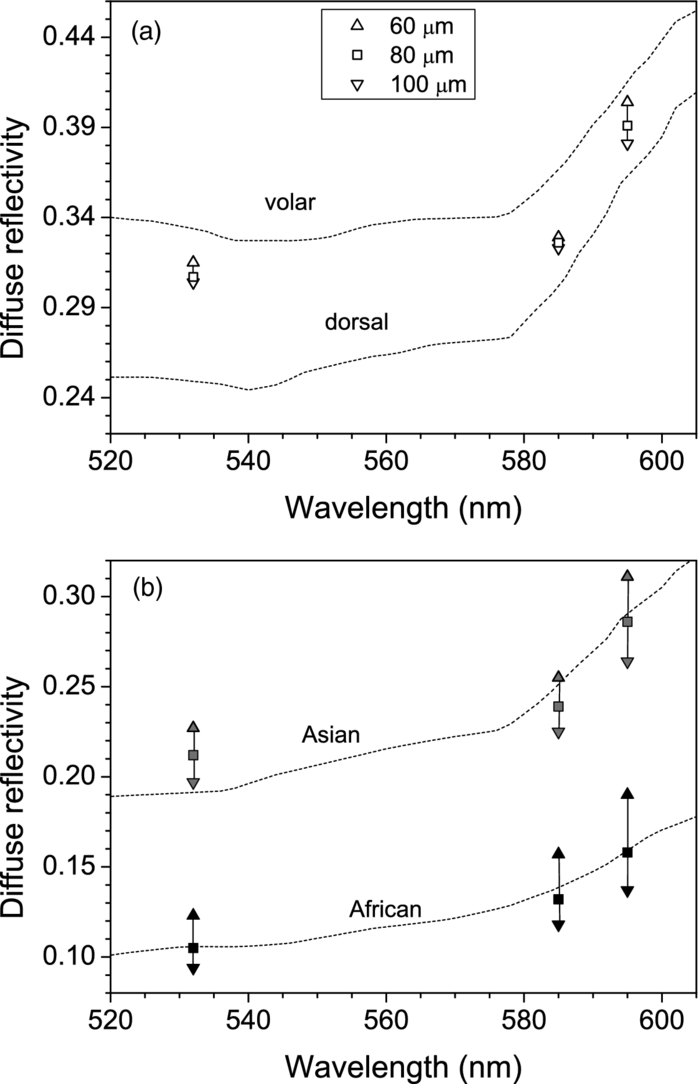 For fair Caucasian skin [Fig. 2a], our diffuse reflectance values (open symbols) fall completely within the range of the DR spectra measured on the volar and dorsal side of the forearm, respectively (dashed lines). In Asian skin [Fig. 2b, gray symbols], the predicted range of DR values matches the reported spectrum rather well. The predicted values at λ = 532 nm are a little higher, but are matched with the experimental report by Randeberg (R = 0.20).34 An excellent match between the predicted DR values and experimental spectrum in vivo is observed for African skin, specifically for epidermal thickness of 80 μm (black squares). Our model results illustrate how an increase in epidermal thickness leads to lower diffuse reflectivity of skin, due to increased melanin absorption. Moreover, this effect is enhanced with increasing melanin content (f m). Consequently, we can observe a substantial change of DR with the epidermal thickness in Asian and African skin phototypes. In contrast, the effect is rather small, and probably often not discernable from experimental data, in fair Caucasian skin. At all three phototypes, however, the largest influence of epidermal thickness on DR is predicted at the longest wavelength, 595 nm. 3.2.Influence of Boundary ConditionBefore embarking on simulations of PWS treatment, we analyze the influence of BC implemented at the sides of the VOI. For this analysis, we augment our model of healthy skin (fair Caucasian; f m = 1.3%), as presented above, with one cylindrical blood vessel in the dermal layer. The vessel (diameter: 120 μm) lies horizontally under the laser beam axis, at a subsurface depth of 0.25 or 0.50 mm. In addition, we consider the case where both vessels are present simultaneously. This enables quantitative assessment of the influence of one vessel on energy uptake in another vessel in close proximity (a.k.a. optical shading). The same geometry was used in one of the first studies of this effect, as well as of optical screening within individual blood vessels, using 3D MC modeling.2 For even closer correspondence, we also set the epidermal thickness to 60 μm, laser beam diameter to 1 mm, and radiant exposure to 1 J/cm2. For each model geometry, we calculate energy deposition maps upon irradiation at 585 nm when applying the mirror or escape BC, and compare them with our extended layer (EL) approach. The resulting energy deposition profiles along the vertical beam axis (passing through both vessels’ axes) are presented in Fig. 3. Clearly, the choice of BC is reflected primarily in the result for the deeper vessel (z 0 = 0.50 mm). For this vessel, using the mirror BC [fig. 3a] results in a 73% larger energy deposition (integrated over the entire vessel lumen) as compared to the EL result [Fig. 3c; see Table 4]. The escape BC [Fig. 3b], on the other hand, results in 16% lower energy deposition in the same vessel than the EL approach. Fig. 3Energy deposition profiles through the axes of two horizontal vessels located at subsurface depth of 0.25 and 0.5 mm (solid black line), compared with the result for a single vessel located at 0.25 mm (thinner, blue), or at 0.5 mm (dashed, red). The boundary condition applied at the sides of the VOI is: (a) mirror, (b) escape, and (c) extended layers.  Table 4Energy deposition per unit length within a single vessel (z 0 = 0.25 or 0.50 mm) and with both vessels present simultaneously (see Fig. 3). Results for three boundary conditions are presented (λ = 585 nm).
For the shallower vessel (z 0 = 0.25 mm), the influence of BC is somewhat less pronounced. Application of the mirror BC results in an overestimation of the energy uptake by 32%, while the escape BC leads to a 7% lower energy deposition estimate as compared to the EL result. The energy deposition results in Table 4 also allow quantitative assessment of optical shading, i.e., the relative change of energy uptake by the presence of a nearby vessel. We can see that the influence of the deeper vessel on the laser energy deposition in the shallower one—albeit not very large—varies strongly with the choice of BC. Specifically, by applying the mirror BC at the side boundaries of the VOI, a reduction of deposited energy by 6.3% is obtained upon introduction of the deeper vessel. This prediction, however, is more than twice as large as the result obtained with the more realistic EL approach (i.e., −2.7%). Applying the escape BC, in contrast, yields to underestimation of the shading effect by ∼30%. The optical shading effect in the deeper vessel, while obviously significantly larger in magnitude (−28%), is affected by selection of either mirror or escape BC to a significantly lesser degree. Figure 4 presents energy deposition profiles through a single vessel (z 0 = 0.25 mm) with diameter of 60 or 120 μm, upon laser irradiation at 532, 585, and 595 nm, when the EL approach is applied. At the wavelength of 595 nm, with the lowest μ a value in blood, the near-central part of the larger vessel (lighter; red solid line) absorbs slightly more laser energy than at 532 and 585 nm (thicker; black and thinner; blue, respectively). This is not the case for the 60 μm vessel (dashed lines), which is almost optically thin (μa d < 1) at the considered wavelengths. Fig. 4Energy deposition profiles through the axis of a single vessel with diameter of 120 μm (solid lines) or 60 μm (dashed), irradiated at 532 nm (thicker black line), 585 nm (thinner; blue), and 595 nm (lighter; red). All results were obtained using the extended layer approach. 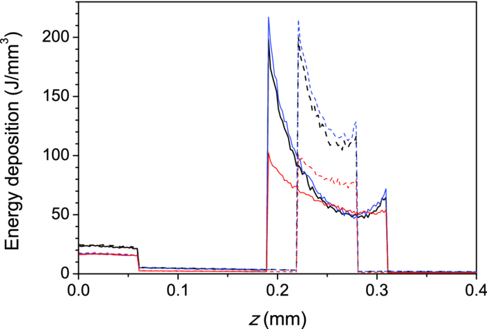 Energy depositions within the vessel lumen from the result in Fig. 4 are compared with predictions obtained when using the mirror and escape BC in Table 5. The largest discrepancy between the mirror BC and EL approach is observed at λ = 595 nm. The mirror BC yields 56% and 48% larger energy depositions in 60 and 120 μm vessels, respectively, as compared to the EL results. The escape BC, in contrast, leads to 11% lower predictions than the EL approach at both vessel diameters. At 532 and 585 nm, similar trends but somewhat smaller relative differences can be observed. Table 5Total energy uptake by vessels of 60 and 120 μm diameter located at 0.25 mm depth, upon irradiation at 532, 585, and 595 nm. Results for all three boundary conditions are presented.
3.3.Deposition of Laser Energy in a Model PWS Blood VesselFigure 5 illustrates spatial distribution of deposited energy in a model PWS vessel, as obtained by our MC simulation upon irradiation with a 5-mm diameter hat-top laser beam at λ = 532 nm in moderately pigmented Middle Eastern or Asian skin (f m = 3.5%). The radiant exposure is H = 7.6 J/cm2, which is just below the epidermal damage threshold (see Secs. 3.5 and 3.6). In the central plane perpendicular to the vessel axis [y = 0.5 mm; Fig. 5a], the energy deposition within the vessel is nonuniform, with the largest values near the top of the vessel lumen. Figure 5b presents the energy deposition in the vertical plane through the vessel axis. Fig. 5Cross-sectional maps of laser energy deposited in a model PWS blood vessel (d = 150 μm, z0 = 400 μm) upon irradiation with a 5-mm diameter hat-top laser beam (l = 532 nm) and radiant exposure H = 7.6 J/cm2 in the central planes: (a) perpendicular to the vessel axis (y = 0.5 mm) and (b) through the vessel axis (x = 0.5 mm).  Figure 6a presents the corresponding lateral energy deposition profile through the vessel axis (y = z = 0.5 mm). The result indicates a dip in perivascular dermis, caused by reduction of light fluence due to strong absorption in the blood vessel. Figure 6b presents the corresponding energy deposition profiles in the direction parallel to the vessel axis (x = 0.5 mm). Energy deposition along the vessel axis (solid black line) is practically constant throughout the VOI, due to a comparatively larger laser beam diameter (d l = 5 mm). Energy deposition along the top of the PWS vessel (lighter, blue line) is significantly larger and shows a slight decrease toward the VOI borders. At the epidermal–dermal (ED) junction, energy deposition is again nearly constant, and larger than in the vessel center (dashed line). Fig. 6Horizontal energy deposition profiles from the result in Fig. 5: (a) through the vessel axis (y = z = 0.5 mm) and (b) along the vessel axis (solid black line), along the top of the vessel lumen (thinner, blue line), and at the epidermal-dermal junction (z = 60 μm; dashed). 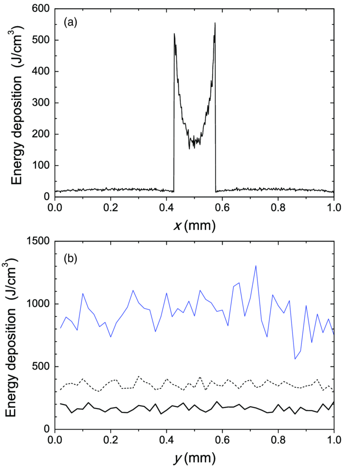 The lower noise level in Figs. 5a, 6a, as compared to Figs. 5b, 6b results primarily from the fact that the former correspond to a 10 times thicker tissue slice than the latter (i.e., Δy = 20 μm versus Δx = 2 μm). In addition, we have averaged 5 centrally located slices to further suppress photon noise in Fig. 5a and obtain a smooth heat source term for Eq. 4. Obviously, the same could not be done in the case of Fig. 5b, leading to rather noisy appearance of the profiles in Fig. 6b. This is not an issue, however, since the latter serves only as an illustration of the model behavior and is not used in the subsequent modeling steps. The central depth profile of energy deposition is very similar to that shown in Fig. 4 (for λ = 532 nm, d = 120 μm), and is therefore not presented. 3.4.Temperature and Coagulation Maps in Laser-Irradiated PWS Blood VesselFigure 7a presents temperature evolution in the model PWS blood vessel from Fig. 5, irradiated with a 1 ms laser pulse at 532 nm after 50 ms long CS cooling, as obtained using our thermal transport model 3. At radiant exposure of H epi = 7.6 J/cm2, just below the epidermal damage threshold, the temperature at the top of the vessel lumen (thinner, blue line) reaches 100°C, but remains below 70°C at the vessel bottom (dashed line). Fig. 7Temperature evolution in laser irradiated PWS: (a) at the top (thinner, blue line), center (black), and bottom (short dashed) of the vessel lumen; and (b) at the epidermal-dermal junction. Radiant exposure is H = 7.6 J/cm2; see text for other details.  Temperature evolution at the ED junction, meanwhile, shows an initial drop to 10°C upon CS precooling, followed by a jump to the maximal temperature of 68°C [Fig. 7b]. Figure 8a presents temperature distribution in the central cross-sectional plane of the model PWS geometry at the end of 1 ms laser pulse irradiation, preceded by 50 ms CS cooling. The temperature at the bottom of the vessel lumen is considerably lower than at the top. Fig. 8(a) Temperature field in the central cross-section of the model PWS geometry (y = 0.5 mm) immediately after pulsed laser irradiation preceded by CS cooling. (b) Temperature depth profiles through the vessel center obtained with (solid line) and without CS precooling (dashed). The radiant exposure values for CS cooling (7.6 J/cm2) and no cooling (4.6 J/cm2) match the respective epidermal damage thresholds, H epi.  The corresponding temperature depth profile through the vessel center is presented in Fig. 8b (solid line) and compared with the result obtained for the case without CS precooling (dashed). Note, however, that these profiles correspond to different radiant exposure values, selected to match the respective epidermal damage thresholds (as determined further below): H epi = 7.6 J/cm2 with CS cooling versus 4.6 J/cm2 without cooling. We can see that the two radiant exposure values indeed result in comparable maximal temperatures within the epidermal layer (T ≈ 80 °C). At the same time, CS cooling allows significantly larger temperatures to be achieved in the lower part of the vessel lumen, as compared to irradiation without precooling. The extent of tissue coagulation, resulting from either treatment approach, is compared in Fig. 9 by presenting the cross-sectional distributions of the damage parameter Ω 4. Coagulation of blood and dermis is indicated by darker gray shades (Ω ≥ 1), while white and magenta areas indicate healthy and partly compromised tissue, respectively. In moderately pigmented Asian skin (f m = 3.5%), used in this model example, the model PWS vessel can be only partly coagulated at the maximal safe radiant exposure allowed for laser treatment without CS cooling [Fig. 9a]. The CS cooling approach [Fig. 9b], in contrast, allows safe application of significantly larger radiant exposure. This enables almost complete coagulation of the model PWS blood vessel, except for the very bottom part of the vessel lumen (white and magenta regions). Fig. 9Cross-sectional maps of the coagulation parameter Ω in PWS model geometry (f m = 3.5%): (a) immediately after irradiation with 1 ms laser pulse after natural convection cooling; (b) after irradiation with 1 ms laser pulse preceded by CS cooling. The radiant exposure in either example is just below the epidermal damage threshold, i.e., 4.6 J/cm2 and 7.6 J/cm2 for (a) and (b), respectively.  3.5.Radiant Exposure ThresholdsFor three laser wavelengths (λ = 532, 585, and 595 nm), two skin phototypes (fair Caucasian and moderately pigmented Asian), and two cooling approaches (no cooling and CS cooling), we determine the minimal radiant exposure, at which the entire lumen of the model PWS vessel is coagulated (H PWS), and the epidermal damage threshold, H epi, as described before. Provided that H epi is larger than H PWS, the interval between the two thresholds indicates the range of safe and therapeutically effective radiant exposure values for the selected skin and treatment conditions. In Fig. 10a, we compare the obtained radiant exposure thresholds for fair Caucasian skin. Clearly, a complete coagulation of the model PWS vessel can be safely achieved at all tested conditions (see the labels). Fig. 10Numerically predicted threshold radiant exposures HPWS and H epi in (a) fair Caucasian skin (f m = 1.3%); and (b) moderately pigmented Asian skin (f m = 3.5%) for laser irradiation at 532, 585, and 595 nm, without (left) and with application of CS cooling (right; note the labels).  Specifically, the smallest safety margin is predicted for PWS treatment at 532 nm without precooling of skin (H epi – H PWS = 2.1 J/cm2). By addition of CS cooling, the epidermal damage threshold (H epi) is markedly increased with almost no effect on H PWS, thus increasing the safety margin to a much more comfortable value of 7.5 J/cm2. These results agree very well with clinical experience. A good fraction of PWS lesions in fair skin could be treated with no adverse side effects using early pulsed 532 nm lasers without CS cooling. However, introduction of the latter has dramatically improved the safety record of PWS therapy. Moreover, by allowing safe use of significantly higher radiant exposures, it has enabled treatment of many “resistant” PWS lesions, featuring deeper and/or larger blood vessels. At the two longer laser wavelengths (585 and 595 nm), with lower absorption in epidermal melanin as compared to 532 nm, the difference H epi – H PWS is considerably larger. For our model geometry, the predicted range of safe yet therapeutically effective radiant exposure values thus amounts to ∼6 J/cm2 without cooling, and raises to ∼13 J/cm2 with application of 50 ms CS cooling. This is also in good agreement with clinical experience, which made such pulsed dye lasers (PDLs) the preferred treatment modality for the majority of PWS patients. In contrast with the above, our results predict that complete coagulation of the model PWS vessel in moderately pigmented Asian skin cannot be obtained safely without application of CS cooling, as H epi < H PWS at all tested wavelengths [Fig. 10b; left part]. With CS cooling (right), however, safe treatment of PWS appears possible at 585 and 595 nm, but with only a marginal difference between H epi and H PWS (1.8 to 2.0 J/cm2). From clinical practice, it is well known that treatment of PWS lesions in patients with moderately and darkly pigmented skin is very challenging, and often impossible, even with up-to-date PDL lasers equipped with CS cooling devices. A more detailed comparison of our predicted therapeutic thresholds with radiant exposures from several clinical reports can be found in Sec. 4. 4.DiscussionIn our experience, the presented EL approach is very effective for high-resolution MC modeling of small inclusions in human skin irradiated with a spatially confined laser beam. As demonstrated in Sec. 3.2, the commonly applied mirror and escape BC can significantly affect predictions of energy deposition when the VOI side boundaries are not positioned sufficiently far from the investigated inclusion and the edge of the laser beam. Specifically, for the case of 1 mm laser beam diameter, the mirror BC produces severely overestimated energy deposition values [compare Figs. 3a, 3c], by up to 73% in the deeper model blood vessel, Table 4). This is a direct consequence of unrealistically slow decrease of light fluence with depth, due to the fact that no photon is allowed to escape through the perfectly reflecting VOI side walls. Such a large discrepancy is not so surprising if we consider that the result obtained with the mirror BC corresponds to the situation where an infinite number of 1 mm laser beams (separated by 1 mm in both x and y direction) would irradiate the skin surface—clearly delivering much more light than a single beam. In addition to the above, we have determined that application of the mirror BC emphasizes mutual shading between nearby blood vessels. Specifically, the relative reduction of energy uptake in the superficial vessel caused by presence of the deeper vessel is overestimated by a factor of 2.3 (Table 4). It is evident that the mirror BC can yield realistic predictions of light transport in a small volume near the center of a sufficiently large laser beam. This was utilized in many earlier models of blood vessel photocoagulation.4, 28, 35, 36 By performing a direct comparison for our PWS model geometry (Fig. 1), we can confirm that this approach predicts practically identical energy deposition profiles as obtained with our EL approach for the 5-mm diameter hat-top laser beam with the same energy density. To be precise, the blood vessel energy uptake obtained with the mirror BC was actually ∼2% lower. We attribute this effect to the fact that the reflecting VOI boundaries produce mirror images of not only the laser source but also of the absorbing structures inside the VOI, thereby reducing the fluence at the corresponding depths, which is not the case with our EL approach. However, without the ability to perform a more realistic computation, it might be very difficult to determine the beam diameter at which the limit of infinitely wide irradiation, inherently implied by the mirror BC, is achieved for any specific combination of tissue optical properties, target structure depth, VOI dimensions, etc. The results in Table 5, for example, show that discrepancies between the mirror BC and our EL approach increase with decreasing absorption coefficient of tissues (from 532 to 595 nm), which can be attributed directly to consequently increasing effective free path. In addition, our EL approach also enables high-resolution modeling of nonuniform (including noncentrosymetric) laser beams, which are not treatable using a small VOI with mirror BC. With the escape BC, in contrast, energy deposition in deeper structures is underestimated, because no photon passing through the VOI side boundaries is scattered back from the surrounding tissue (Fig. 3, Tables 4, 5). This is evidently physically inaccurate for human skin, but—for the discussed wavelengths, and model geometry—the related artifacts are smaller than in the case of mirror BC. Clearly, the influence of such artifacts can be reduced, and eventually eliminated, by positioning the VOI side boundaries of the escape type sufficiently far from both the investigated structure and the laser beam edge, and many earlier studies have adopted this approach.3 But, when high-resolution 3D modeling involving relatively large laser beams is required, this may come at a very high price. For the purpose of illustration, we turn again to our PWS model geometry and the 5 mm diameter hat-top laser beam. By extending the VOI with escape BC to 6 × 6 × 1.5 mm3, the computation time for a run involving 107 photons amounted to 57 h and 27 min on our personal computer (Core i7 870 processor by Intel; 8 GB of DDR3 RAM), despite the use of multithreading. With the EL approach, meanwhile, it took only 17 min to obtain the same results in the central 1 × 1 × 1.5 mm3 volume of interest, which is more than 200 times faster. Moreover, note that we could only perform this comparison by reducing the spatial resolution. At the applied VOI discretization (4 × 20 × 4 μm3), 1288 MB of RAM were namely used just to store the energy deposition matrix for the escape BC example. At the finer discretization, as used for our entire study, this matrix would have been 4 times larger, likely preventing the program from running at all. In our EL implementation, used for all presented examples, the energy deposition matrix meanwhile consumes only 572 MB of RAM at the finer VOI discretization. When we compare our predictions of laser damage thresholds (Fig. 10) with radiant exposure values used in published PWS clinical studies, we find a rather good agreement. In one study,37 radiant exposure of 10 J/cm2 at λ = 532 nm was applied successfully to patients with skin types I–III, without active cooling of skin. The laser pulse duration was 6 ms and beam diameter 1 mm. For fair Caucasian skin and the same wavelength, our results indicate the epidermal damage threshold at H epi = 8.8 J/cm2, but for a shorter laser pulse duration (t p = 1 ms) and larger beam diameter (d b = 5 mm). Note that the longer pulse duration enables partial thermal relaxation of the epidermis during the irradiation, which increases H epi. Similarly, the laser beam diameter of 1 mm as used in the clinical study will result in a faster decrease of light fluence with depth inside the skin as compared to 5 mm,38 thus resulting in a further increase of the epidermal damage threshold. Both effects are reproduced in our numerical model. In another clinical study at 532 nm,39 radiant exposure of 7 J/cm2 (t p = 2 ms, d b = 3 mm) was applied with contact cooling of skin, with no adverse effects observed in the patients. Our simulation results indicate H epi = 14.2 J/cm2 for fair Caucasian and 7.6 J/cm2 for moderately pigmented Asian skin, respectively. The expected increase of H epi due to the somewhat longer laser pulse and smaller beam diameter used in this clinical trial (as compared to those considered in our simulation) is offset, at least in part, by the smaller efficacy of the contact cooling device with respect to CS cooling.40 Without having run our model for those particular conditions, it is hard to give a reliable verdict, but the radiant exposure values mentioned above certainly do not appear to be conflicting. At λ = 585 nm, radiant exposure of 6.75 J/cm2 (applied without skin cooling) was reported to result in 11% incidence of adverse effects in patients with skin types I–IV (at t p = 1.5 ms and d b = 7 mm).41 In our simulation results, H epi = 11.2 J/cm2 is predicted for fair Caucasian skin, dropping to 6.1 J/cm2 for moderately pigmented Asian skin, which represents an excellent match with the clinical observations stated above. In another study,42 where CS cooling was used with a 585 nm laser (t p = 1.5 ms, d b = 5 mm), radiant exposures between 11 and 20 J/cm2 were used successfully in patients with skin types I–V. Our simulation predictions (H epi = 17.4 and 9.8 J/cm2 for fair Caucasian and Asian skin, respectively) match these observations reasonably well, given the small difference in laser pulse duration and known variability of different CS cooling devices. At 595 nm, application of H = 15 J/cm2 with CS cooling was reported to cause no permanent adverse effects in patients with skin phototypes I–IV (t p = 1.5 ms, d b = 7 mm).39 This is in good agreement with our prediction of H epi = 19.3 J/cm2 in fair Caucasian skin (at t p = 1 ms). According to our simulation, the above radiant exposure value would cause problems in patients with moderately pigmented Asian skin (H epi = 9.9 J/cm2), but these would probably have been categorized as phototype V and thus not enrolled in the study. In addition, our modeling of the CS cooling is rather conservative. Heat transfer coefficient values significantly higher than H = 5000 W/m2K were assessed for some commercial CS cooling devices,26 and the treating physician may choose a longer cooling time than the modeled 50 ms, which would both lead to a higher threshold for epidermal injury. All in all, our numerically predicted radiant exposure thresholds correlate very well with the reported clinically applied values for therapy of PWS, when taking into account the differences in other laser parameter parameters (pulse duration, beam diameter). The occasional discrepancies could result from the mismatch in CS cooling settings and efficacy, etc. On top of that, the well-known variations in PWS blood vessel size and depth distribution on an individual patient basis affect the respective values of H PWS and—to a smaller degree—also H epi, thus introducing significant differences in lesion response to laser therapy that can be safely administered. When all these parameters are kept constant in the model, however, the observed trends with respect to laser wavelength, cooling approach, and skin phototype (see Fig. 10) match common knowledge in the field. With the above stated reservations in mind, we therefore believe that the presented numerical model is sufficiently realistic to allow provisional exploration of novel treatment approaches and protocols, including those involving as yet unavailable equipment. For example, an earlier numerical and animal model study showed that dividing the radiant exposure into multiple laser pulses (MLP), while controlling the epidermal temperature rise by application of multiple cryogen spurts (MCS), can allow safe photocoagulation of significantly larger subsurface blood vessels as compared to the customary single-pulse treatment.23 We have recently applied a similar numerical model as presented above to assess the optimal values of additional free parameters in such MCS-MLP treatment approach (i.e., repetition rate, number of CS-laser pulse pairs).20 The results suggested that specific MCS-MLP sequences provide significantly higher efficacy and safety as compared to the customary treatment, across a wide range of PWS blood vessel diameters and depths. Such an approach may thus lead to an improved therapeutic outcome for patients with darker skin and/or PWS featuring blood vessels of larger caliber, which are currently untreatable due to high risk of permanent epidermal injury [see Fig. 9b]. 5.ConclusionsThe presented 3D MC optical model with a novel approach to treatment of the VOI side boundaries represents a very flexible and effective approach to high-resolution treatment of small volumes in human skin with arbitrary inclusions, irradiated with spatially confined laser beams. A direct comparison shows that the energy deposition maps differ significantly from those obtained using the escape and mirror boundary conditions even for simple, plausible model geometries. The model reproduces realistic values of diffuse reflectance for normal skin and, when augmented with a model of thermal transport and tissue coagulation kinetics, realistic values of radiant exposure thresholds for epidermal injury and for photocoagulation of PWS blood vessels in various skin phototypes, with or without application of cryogen spray cooling. AcknowledgmentsWe wish to acknowledge Dr. T. Joshua Pfeffer and Dr. Wangcun Jia for helpful discussions. ReferencesL. Wang,
S. L. Jacques, and
L. Zheng,
“MCML - Monte Carlo modeling of light transport in multi-layered tissues,”
Comp. Methods Programs Biomed., 47
(2), 131
–146
(1995). https://doi.org/10.1016/0169-2607(95)01640-F Google Scholar
G. W. Lucassen,
W. Verkruysse,
M. Keijzer, and
M. J. C. van Gemert,
“Light distributions in a port wine stain model containing multiple cylindrical and curved blood vessels,”
Lasers Surg. Med., 18 345
–357
(1996). https://doi.org/10.1002/(SICI)1096-9101(1996)18:4<345::AID-LSM3>3.0.CO;2-S Google Scholar
T. J. Pfefer,
J. K. Barton,
E. K. Chan,
M. G. Ducros,
B. S. Sorg,
T. E. Milner,
J. S. Nelson, and
A. J. Welch,
“A three dimensional modular adaptable grid numerical model for light propagation during laser irradiation of skin tissue,”
IEEE J. Sel. Topics Quantum Electron., 2 934
–942
(1996). https://doi.org/10.1109/2944.577318 Google Scholar
J. K. Barton,
T. J. Pfefer,
A. J. Welch,
D. J. Smithies,
J. S. Nelson, and
M. J. C. van Gemert,
“Optical Monte Carlo modeling of a true port wine stain anatomy,”
Opt. Express, 2 391
–396
(1998). https://doi.org/10.1364/OE.2.000391 Google Scholar
R. R. Anderson and
J. A. Parrish,
“Selective photothermolysis: Precise microsurgery by a selective absorption of pulsed radiation,”
Science, 220 524
–527
(1983). https://doi.org/10.1126/science.6836297 Google Scholar
J. S. Nelson,
T. E. Milner,
B. Anvari,
B. S. Tanenbaum,
S. Kimel,
L. O. Svaasand, and
S. L. Jacques,
“Dynamic epidermal cooling during pulsed laser treatment of port-wine stain,”
Arch. Dermatol., 131 695
–700
(1995). https://doi.org/10.1001/archderm.131.6.695 Google Scholar
L. O. Svaasand,
L. T. Norvang,
E. J. Fiskerstrand,
E. K. S. Stopps,
M. W. Berns, and
J. S. Nelson,
“Tissue parameters determining the visual appearance of normal skin and port-wine stains,”
Laser Med. Sci., 10 55
–65
(1995). https://doi.org/10.1007/BF02133165 Google Scholar
S. L. Jaques,
“Melanosome absorption coefficient,”
(1998) http://omlc.ogi.edu/spectra/melanin/mua.html Google Scholar
M. Meinke,
G. Müller,
J. Helfmann, and
M. Friebel,
“Optical properties of platelets and blood plasma and their influence on the optical behavior of whole blood in the visible to near infrared wavelength range,”
J. Biomed. Opt., 12 014024
(2007). https://doi.org/10.1117/1.2435177 Google Scholar
A. N. Bashkatov,
E. A. Genina,
V. I. Kochubey, and
V. V. Tuchin,
“Optical properties of the subcutaneous adipose tissue in the spectral range 400–2500 nm,”
Opt. Spectrosc., 99 836
–842
(2005). https://doi.org/10.1134/1.2135863 Google Scholar
S. T. Flock,
B. C. Wilson, and
M. S. Patterson,
“Total attenuation coefficients and scattering phase functions of tissues and phantom materials at 633-nm,”
Med. Phys., 14 835
–841
(1987). https://doi.org/10.1118/1.596010 Google Scholar
E. J. Fiskerstrand,
L. O. Svaasand,
G. Kopstad,
M. Dalaker,
L. T. Norvang, and
G. Volden,
“Laser treatment of port wine stains: therapeutic outcome in relation to morphological parameters,”
Br. J. Dermatol., 134 1039
–1043
(1996). https://doi.org/10.1111/j.1365-2133.1996.tb07939.x Google Scholar
S. H. Barsky,
S. Rosen,
D. E. Geer, and
J. M. Noe,
“The nature and evolution of port wine stains: A computer-assisted study,”
J. Invest. Dermatol., 74 154
–157
(1980). https://doi.org/10.1111/1523-1747.ep12535052 Google Scholar
E. V. Ross and
Y. Domankevitz,
“Laser treatment of leg veins: physical mechanisms and theoretical considerations,”
Laser Surg. Med., 36
(2), 105
–116
(2005). https://doi.org/10.1002/lsm.20141 Google Scholar
W. Verkruysse,
G. W. Lucassen,
J. F. de Boer,
D. J. Smithies,
J. S. Nelson, and
M. J. C. van Gemert,
“Modeling light distributions of homogenous versus discrete absorbers in light irradiated turbid media,”
Phys. Med. Biol., 42 51
–65
(1997). https://doi.org/10.1088/0031-9155/42/1/003 Google Scholar
B. Choi,
B. Majaron, and
J. S. Nelson,
“Computational model to evaluate port wine stain depth profiling using pulsed photothermal radiometry,”
J. Biomed. Opt., 9
(2), 299
–307
(2004). https://doi.org/10.1117/1.1646173 Google Scholar
J. W. Valvano,
“Tissue thermal properties and perfusion,”
Optical-thermal Response of Laser-irradiated Tissue, 2nd ed.Springer Verlag, Dordrech
(2011). Google Scholar
A. J. Welch,
E. H. Wissler, and
L. A. Priebe,
“Significance of blood-flow in calculations of temperature in laser irradiated tissue,”
IEEE Trans. Biomed. Eng., 27 164
–166
(1980). https://doi.org/10.1109/TBME.1980.326619 Google Scholar
M. Stucker,
V. Bajer,
T. Reuther,
K. Hoffman,
K. Kellam, and
P. Altmeyer,
“Capillary blood cell velocity in human skin capillaries located perpendicularly to the skin surface: Measured by a new laser Doppler anemometer,”
Microvasc. Res., 52 188
–192
(1996). https://doi.org/10.1006/mvre.1996.0054 Google Scholar
M. Milanič,
W. Jia,
J. S. Nelson, and
B. Majaron,
“Numerical optimization of sequential cryogen spray cooling and laser irradiation for improved therapy of port wine stain,”
Laser Surg. Med., 43 164
–75
(2011). https://doi.org/10.1002/lsm.21040 Google Scholar
F. Xu,
A. Seffen, and
T. J. Lu,
“Temperature-dependent mechanical behaviors of skin tissue,”
IAENG Int. J. Comp. Sci., 35 92
–101
(2008). https://doi.org/10.1.1.149.855 Google Scholar
G. Shafirstein,
W. Baumler,
M. Lapidoth,
S. Ferguson,
P. E. North, and
M. Waner,
“A new mathematical approach to the diffusion approximation theory for selective photothermolysis modeling and its implication in laser treatment of port-wine stains,”
Laser Surg. Med., 34 335
–47
(2006). https://doi.org/10.1002/lsm.20028 Google Scholar
W. Jia,
B. Choi,
W. Franco,
J. Lotfi,
B. Majaron,
G. Aguilar, and
J. S. Nelson,
“Treatment of cutaneous vascular lesions using multiple-intermittent cryogen spurts and two-wavelength laser pulses: Numerical and animal studies,”
Laser Surg. Med., 39
(6), 494
–503
(2007). https://doi.org/10.1002/lsm.20524 Google Scholar
CRC Handbook of Chemistry and Physics, 89th Ed.CRC Press, Boca Raton, Florida
(2008). Google Scholar
B. Majaron,
L. O. Svaasand,
G. Aguilar, and
J. S. Nelson,
“Intermittent cryogen spray cooling for optimal heat extraction during dermatologic laser treatment,”
Phys. Med. Biol., 47
(18), 3275
–3288
(2002). https://doi.org/10.1088/0031-9155/47/18/301 Google Scholar
L. O. Svaasand,
L. L. Randeberg,
G. Aguilar,
B. Majaron,
S. Kimel,
E. J. Lavernia, and
J. S. Nelson,
“Cooling efficiency of cryogen spray during laser therapy of skin,”
Laser Surg. Med., 32
(2), 137
–142
(2003). https://doi.org/10.1002/lsm.10120 Google Scholar
A. M. K. Nilsson,
G. W. Lucassen,
W. Verkruysse,
E. S. Andersson, and
M. J. C. van Gemert,
“Changes in optical properties of human whole blood in vitro due to slow heating,”
Photochem. Photobiol., 65 366
–373
(1997). https://doi.org/10.1111/j.1751-1097.1997.tb08572.x Google Scholar
J. K. Barton,
A. Rollins,
S. Yazdanfar,
T. J. Pfefer,
V. Westphal, and
J. A. Izatt,
“Photothermal coagulation of blood vessels: a comparison of high-speed optical coherence tomography and numerical modelling,”
Phys. Med. Biol., 46 1665
–78
(2001). https://doi.org/10.1088/0031-9155/46/6/306 Google Scholar
D. C. Gaylor,
“Physical mechanism of cellular injury in electrical trauma,”
Massachusetts Institute of Technology,
(1989). Google Scholar
B. Chen,
S. L. Thomsen,
R. J. Thomas,
J. Oliver, and
A. J. Welch,
“Histological and modeling study of skin thermal injury to 2.0 mm laser irradiation,”
Lasers Surg. Med., 40 358
–370
(2008). https://doi.org/10.1002/lsm.20630 Google Scholar
F. C. Henriques,
“Studies of thermal injury; the predictability and the significance of thermally induced rate processes leading to irreversible epidermal injury,”
Arch. Pathol., 43 489
–502
(1947). Google Scholar
J. Sandby-Moeller,
T. Poulsen, and
H. C. Wulf,
“Epidermal thickness at different body sites: Relationship to age, gender, pigmentation, blood content, skin type and smoking habits,”
Acta Derm. Venereol., 83 410
–13
(2003). https://doi.org/10.1080/00015550310015419 Google Scholar
S. Neerken,
G. W. Lucassen,
M. A. Bisschop,
E. Lenderink, and
T. A. Nuijs,
“Characterization of age-related effects in human skin: a comparative study that applies confocal laser scanning microscopy and optical coherence tomography,”
J. Biomed. Opt., 9 274
–81
(2004). https://doi.org/10.1117/1.1645795 Google Scholar
L. L. Randeberg,
O. A. Haugen,
R. Haaverstad, and
L. O. Svaasand,
“A novel approach to age determination of traumatic injuries by reflectance spectroscopy,”
Laser Med. Sci., 38 277
–89
(2006). https://doi.org/10.1002/lsm.20301 Google Scholar
T. J. Pfefer,
J. K. Barton,
D. J. Smithies,
T. E. Milner,
J. S. Nelson,
M. J. C. van Gemert, and
A. J. Welch,
“Modeling laser treatment of port wine stains with a computer-reconstructed biopsy,”
Laser Surg. Med., 24 151
–166
(1999). https://doi.org/10.1002/(SICI)1096-9101(1999)24:2<151::AID-LSM11>3.0.CO;2-0 Google Scholar
T. J. Pfefer,
D. J. Smithies,
T. E. Milner,
M. J. C. van Gemert,
J. S. Nelson, and
A. J. Welch,
“Bioheat transfer analysis of cryogen spray cooling during laser treatment of port wine stains,”
Laser Surg. Med., 26 145
–157
(2000). https://doi.org/10.1002/(SICI)1096-9101(2000)26:2<145::AID-LSM5>3.0.CO;2-0 Google Scholar
C. Clark,
H. Cameron,
H. Moseley,
J. Ferguson, and
S. H. Ibbotson,
“Treatment of superficial cutaneous vascular lesions: experience with the KTP 532 nm laser,”
Laser Med. Sci., 19 1
–5
(2004). https://doi.org/10.1007/s10103-004-0294-x Google Scholar
M. Keijzer,
J. W. Pickering, and
M. J. C. van Gemert,
“Laser-beam diameter for port wine stain treatment,”
Laser Surg. Med., 11 601
–605
(1991). https://doi.org/10.1002/lsm.1900110616 Google Scholar
W. K. Woo,
Z. F. Jasim, and
J. M. Handley,
“Evaluating the efficacy of treatment of resistant portwine stains with variable-pulse 595-nm pulsed dye and 532-nm Nd:YAG lasers,”
Dermatol. Surg., 30 158
–16
(2004). https://doi.org/10.1046/j.1076-0512.2003.30055.x Google Scholar
J. S. Nelson,
B. Majaron, and
K. M. Kelly,
“Active skin cooling in conjunction with laser dermatologic surgery: Methodology and clinical results,”
Semin. Cutan. Med. Surg., 19 253
–266
(2000). https://doi.org/10.1053/sder.2000.18365 Google Scholar
A. Yung and
R. Sheehan-Dare,
“A comparative study of a 595-nm with a 585-nm pulsed dye laser in refractory port wine stains,”
Br. J. Dermatol., 153 601
–606
(2005). https://doi.org/10.1111/j.1365-2133.2005.06707.x Google Scholar
K. Scherer,
S. Lorenz,
M. Wimmershoff,
M. Landthaler, and
U. Hohenleutner,
“Both the flashlamp-pumped dye laser and the long-pulsed tunable dye laser can improve results in port-wine stain therapy,”
Br. J. Dermatol., 145 79
–84
(2001). https://doi.org/10.1046/j.1365-2133.2001.04285.x Google Scholar
|
|||||||||||||||||||||||||||||||||||||||||||||||||||||||||||||||||||||||||||||||||||||||||||||||||||||||||||||||||||||||||||||||||||||||||||||||||||||||||||||||||||||||||||||||||||||||||||||||||||||||||||||||||||||


