
|
|
1.IntroductionPerforming a long-term and high-throughput developmental analysis of optically manipulated oocytes is difficult. This difficulty may be due to several factors: (1) oocyte nonadherence to microscopy imaging dishes, (2) altered oocyte position over time caused by stage movements and media convection, and (3) the inability to change the culture media without perturbing the location of the oocytes. The most common approach to stabilizing the oocyte is the use of a vacuum (holding) pipette.1,2,3 Since each oocyte requires its own pipette, this method limits the experimental throughput. Oocytes can also be immobilized by adherence to chemically coated coverglasses.4 This method, however, is prone to cause overadhesion and unwanted cell surface effects. To allow for the high-throughput analysis of experimentally manipulated oocytes over a long time period, an automated optofluidic laser microscopy system has been developed. The fluidic components of the system utilize polydimethylsiloxane (PDMS) soft lithography that was developed a little over 10 years ago.5,6 Subsequently soft lithography has been applied to the mechanical characterization of oocytes as well as the production of artificial oocytes.7,8 Additionally, over the decade microfluidics have been combined with optics to manipulate various somatic cells.9,10 Studies have been performed combining microfluidics with optical ablation for the long-term and high-throughput analysis of oocytes. A system has been created that combines both microfluidics and optical ablation to analyze the structure-function relationship of oocyte organelles. In particular, a validation study was performed where surf clam (Spisula solidissima) oocytes were observed after organelle ablation. These experiments have suggested that a targeted organelle, the nucleolinus, controls meiotic cell division in Spisula solidissima oocytes. First described at least 150 years ago, the nucleolinus is a RNA-rich organelle located within the nucleolus (Fig. 1).11 It has a proposed role in the formation of the spindle in cell division.12,13,14 To explore this role, we have used laser microsurgery to damage the nucleolinus in Spisula solidissima oocytes. After ablation, cells were exposed to potassium chloride, an artificial parthenogenesis agent, to activate the first steps in meiotic cell division. Potassium chloride works by biochemically activating the -phase promoting factor system; this causes changes to intracellular calcium dynamics.13,15 After laser microablation of the nucleolinus the oocytes are maintained in the microfluidic system, and followed to determine whether subsequent ejection of the polar body, an indication of successful meiotic division, had occurred. This experiment validates the use of the optofluidic system for high-throughput optical ablation and subsequent long term analysis. Fig. 1(a) An unactivated surf clam (Spisula solidissima) oocyte viewed under differential interference contrast (DIC). The nucleolinus is an intra-nuclear organelle that has a suspected role in regulating meiotic cell division. The diameter of nucleolinus is approximately 5 µm and the oocyte is approximately 60 µm. (b) A surf clam oocyte 30 min post-activation viewed under DIC. After activation, the nucleus breaks down and a polar body is ejected from the side of the cell, a sign of the first meiotic division.  2.Materials and Methods2.1.Optical DesignThe laser microablation part of the system consists of a Spectra Physics Duo 210 (337 nm wavelength, 4 ns pulse width, 75 kW peak power, 6 mW average power, 60 Hz repetition rate) nitrogen laser (Newport, Newport, CA, USA) coupled to a Zeiss Observer A1 inverted microscope with a oil immersion (phase III, NA 1.3, EC Plan-Neofluar) objective lens (Carl Zeiss MicroImaging, Thornwood, NY, USA). The objective lens transmission at 337 nm was measured to be using a modified dual objective method.16,17 The preobjective power was determined to be 20 µW using a laser light meter (Thorlabs, Newton, NJ, USA). The laser beam was focused to a diameter of 3 µm in the center of the approximately 5 µm nucleolinus for 1 sec (60 pulses at 60 Hz). The total energy delivered at the focal plane was 8 µJ (per pulse energy was 0.13 µJ) with an average irradiance of , and a peak irradiance of . In addition to phase contrast imaging, the microscope was also equipped with differential interference contrast (DIC) imaging, which allowed for easier visualization of the nucleolinus. Phase and DIC images were captured using an Orca R2 (12-bit, ) CCD camera (Hamamatsu, Hamamatsu, Shizuoka, Japan) mounted on the microscope side port. Image acquisition and laser targeting were controlled using a custom Robolase Labview (National Instruments, Austin, TX, USA) algorithm previously described.18 2.2.Fluidic DesignThe oocytes were separated into channels and prevented from moving using microfabricated barriers (see results for a detailed design description). To create the master mold, transparency masks were created in Illustrator (Adobe, San Jose, CA, USA) and printed at 3600 dots per inch (DPI) on transparencies (Stats Prepress, San Diego, CA, USA). The masks were then mounted on borosilicate glass (McMaster Carr, Elmhurst, IL, USA) using double-sided tape. In clean-room conditions 10 mL of SU-8 50 (MicroChem, Newton, MA, USA) was poured onto silicon wafers (Wafer World, West Palm Beach, FL, USA). The wafers were then spin-coated at 400 revolutions per minute (RPM) at an acceleration of for 20 sec. Subsequently the speed was increased to 3000 RPM with an acceleration of for 3 min. This yielded an approximate height of 26 µm, which was enough to trap the surf clam oocytes with diameters of approximately 60 µm. The heights of the channels were measured using a Dektak 150 profilometer (Veeco, Plainview, NY, USA). The wafer was baked at 65°C for 5 min and at 95°C for 15 min to evaporate solvents and stiffen the SU-8. Afterward, 90 sec of UV exposure () through the transparency mask on a mask aligner (Neutronix-Quintel, Morgan Hill, CA, USA) was used to crosslink selected portions of the SU-8 corresponding to the design pattern. The wafer was next baked at 65°C for 5 min and at 95°C for 15 min to enhance SU-8 crosslinking. It was then washed in SU-8 developer (MicroChem) for 6 min to remove the uncrosslinked portions of the SU-8. Wafers were cleaned with isopropyl alcohol and dried with compressed nitrogen. A final bake at 115°C for 1 h was conducted to evaporate any remaining developer and further solidify the SU-8 photoresist. After baking, a second layer of SU-8 was added and processed using a similar method as the first layer. First, another 10 mL of SU-8 50 was placed on the wafer. The wafer was initially spin-coated at 500 RPM for 20 sec and increased to 1000 RPM for 3 min. This created an additional layer making the total height . This height is sufficient to allow surf clam oocytes to flow through the channels. The wafer was then baked at 65°C for 10 min and at 95°C for 30 min. Subsequently the wafer was exposed to UV light at for 120 sec through the photolithography mask inside the mask aligner. The wafer was next baked at 65°C for 5 min and at 95°C for 25 min. Following this, the wafer was washed with SU-8 developer for 10 min, cleaned with isopropyl alcohol, and dried with compressed nitrogen. It was then baked at 115°C for 1 h. Sylgard 184 silicone elastomer base was mixed with Sylgard 184 curing agent in a ratio (Dow Corning, Midland, MI, USA). Bubbles were removed from the mixture using a vacuum desiccator. In a separate desiccator, 2 mL trichloromethylsilane (Sigma-Aldrich, Saint Louis, MO, USA) was evaporated onto the master mold to allow for an easier release of the elastomer. The resulting elastomer mixture was poured onto the master mold and cured at 80°C for 20 min. After curing, the elastomer was peeled off and trimmed. A 3 mm skin biopsy punch (Acuderm, Fort Lauderdale, FL, USA) was used to create the input hole and a 20 gauge (0.603 mm inner diameter and 0.908 mm outer diameter) blunt-tip needle (McMaster Carr) was used to create the output hole. The microfluidic chamber was mounted onto a cover glass (Thermo Fisher Scientific, Waltham, MA, USA). The outlet port was connected to a dual-syringe infusion/withdrawal pump (KD Scientific, Holliston, MA, USA) via 0.79 mm inner diameter and 2.4 mm outer diameter Tygon tubing (Saint-Gobain, Courbevoie, France). The syringe pump was used in the withdrawal mode to pull the input solution through the chamber. Syringe pump actuation was controlled by a custom Labview algorithm using RS-232 commands (9600 baud rate, 8 data bits, no parity, no flow control) called by Labview’s VISA (Virtual Instrument Software Architecture) functions. 2.3.Fluidic Validation Using BeadsPrototype microfluidic chambers were fabricated as described in Sec. 2.2. Polystyrene beads (Duke Scientific, Palo Alto, CA, USA) with diameters of were used to mimic oocytes during barrier testing. During the testing of the media changing, solutions of phosphate buffer solution (PBS) and 1 mM fluorescein in PBS (Sigma-Aldrich, Saint Louis, MO, USA) were interchanged. Fluorescence imaging was conducted using the Observer A1 microscope and Orca R2 camera described in Sec. 2.1. Fluorescent excitation was provided by an X-Cite 120 mercury vapor short arc lamp (Lumen Dynamics, Ontario, Canada) and was coupled through a EGFP filter cube (Chroma Technology, Bellows Falls, VT, USA). 2.4.Optofluidic Validation Using OocytesGravid surf clams, Spisula solidissima, were provided by the Marine Resources Center at the Marine Biological Laboratory (Woods Hole, MA, USA). Ovaries were dissected to release oocytes, which were rinsed in 0.45 μm filtered seawater. Immediately after washing, oocytes were shipped on ice overnight for experimentation and analysis in San Diego. At room temperature, oocytes were loaded into the microfluidic chamber and ablated as described in Sec. 3.3. After irradiation, the oocytes were exposed to 0.07 M KCL by adding 0.5 M KCl into the media. Cells were observed for 50 min to determine whether or not polar body ejection had occurred. In addition to irradiation/ablation of the nucleolinus, two series of controls were performed: (1) no irradiation, and (2) irradiation inside the nucleolus but outside of the nucleolinus. A chi-square test was used to compare the nucleolinus-irradiated cells with the control cells.19 3.Results3.1.Microfluidic DesignThe microfluidic chamber allows for the high-throughput long-term analysis of oocytes following laser microirradiation of the nucleolinus (Fig. 2 and Fig. 3). Oocytes are initially loaded into the inlet port of the microfluidic chamber. Employing Labview, the syringe pump is operated to draw the oocytes into the channels and against the barrier (Fig. 4). By leaving the syringe pump on, a continuous flow of fresh media and oxygen can reach the cells. This constant flow is beneficial for oocytes, which require oxygen for successful development.20,21 Also the media can be easily exchanged by switching the media in the inlet port. Fig. 2Side cross-sectional view of the microfluidic chamber (not drawn to scale). (a) Small quantities of oocytes are introduced into the inlet port and a syringe pump pulls the oocytes into the channels. The channel height is 86 µm, which allows for 60 µm diameter oocytes to flow through. Oocytes are stopped by a physical barrier that only allows filtered sea water to flow through a 26 µm high channel to the outlet port. (b) Oocytes are irradiated using a focused 337 nm UV beam. (c) 14% KCl/filtered sea water is perfused through the channel to activate the oocytes. (d) Fresh media is continuously changed using the syringe pump. Cells are checked for polar body ejections after 50 min. 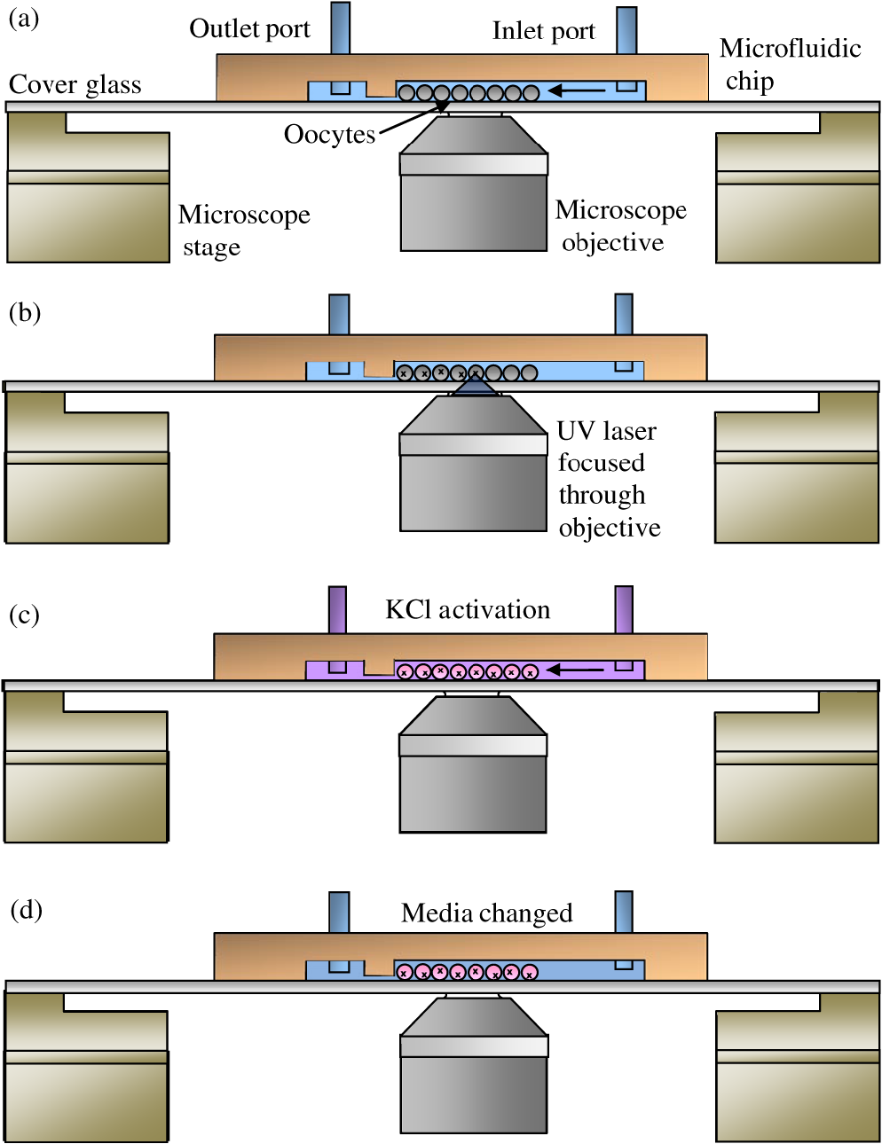 Fig. 3Top view of the microfluidic chamber. Oocytes enter through the inlet port and are pulled through the chamber by a syringe pump connected to the outlet port. The oocytes then flow into 32 individual channels. In each channel, there is a microfluidic barrier that traps the cells. Oocytes in each channel can be subjected to one of three different experimental conditions: no ablation, nucleolinus ablation, or nucleolus ablation. By having separate channels, an oocyte’s location and experimental condition can be recovered easily by recording its channel number.  Fig. 4One channel being loaded with oocytes under DIC. Oocytes are loaded into the inlet port and flow towards the channels (not shown). Once in the channels, the oocytes are blocked by the microfluidic barrier (flow is from the top to the bottom of the images). Image series is taken over 30 sec. 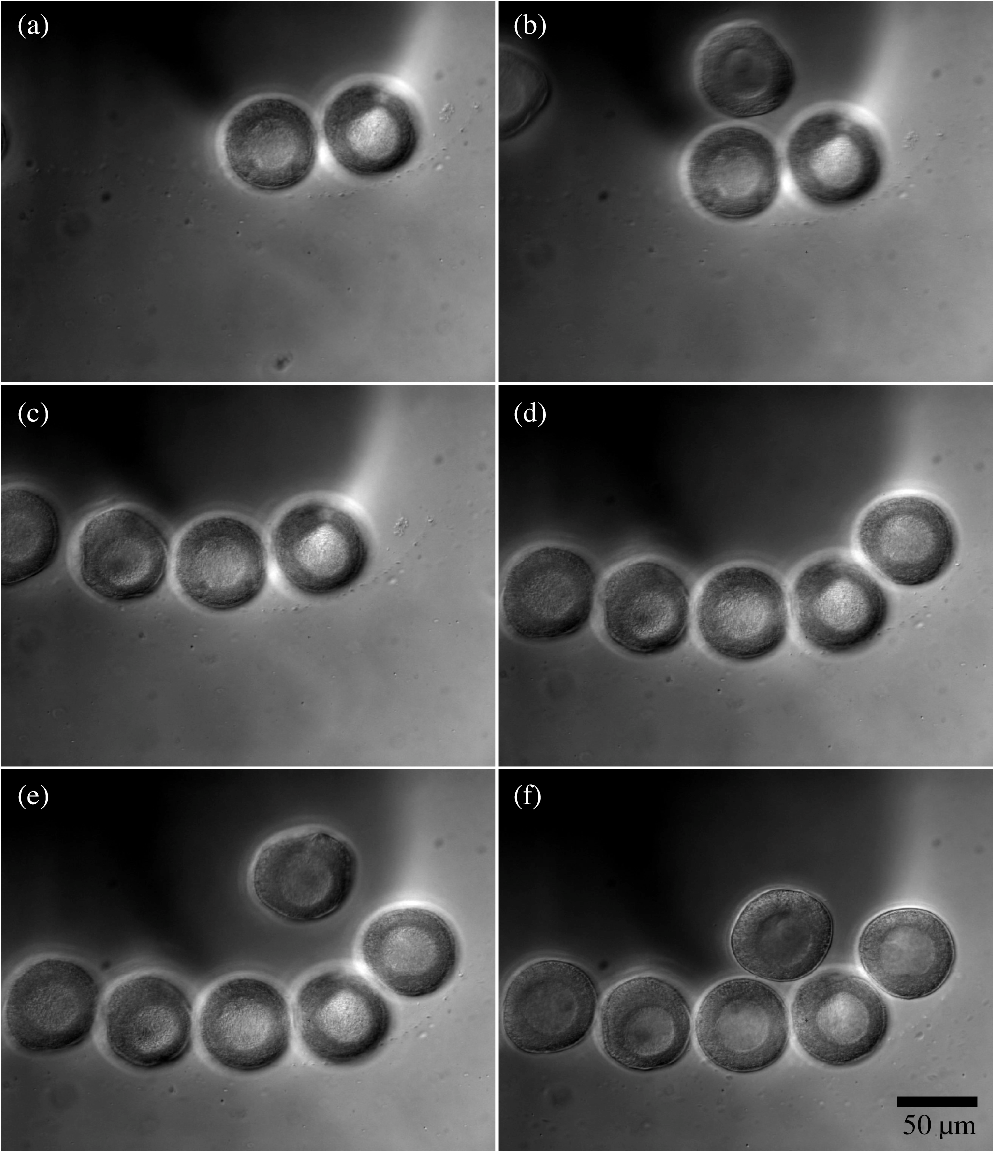 A key design consideration was the choice of device materials. For precise optical ablation it is essential to use a high numerical aperture (NA) objective for focusing the laser into the oocyte. The laser ablation portion of the system uses an inverted microscope with a 1.3 NA oil immersion objective which requires pairing with a thick cover glass. These thin cover glasses are used due to the short working distances of high NA objectives. This ablation requirement forces the microfluidic device to use this cover glass for its base. Other materials would not be able to match the index of refraction or the uniform thickness provided by the glass. The rest of the chamber was comprised of PDMS due to its ease of manufacture, high optical transparency, and low toxicity.5,6,22 Oocyte viability was investigated in this new device environment with unnatural surface wetting and mechanical properties. Compared to control oocytes in standard glass-bottom dishes, oocytes in the microfluidic chambers showed similar cell morphology and polar body ejection rates. The health of the oocytes within the microfluidic chamber is likely due to both the low toxicity of the PDMS and the oocyte’s nonadherent membrane minimally interacting with the device surfaces. An additional microfluidic design consideration was the choice between a single layer-based vertical barrier and a multilayer-based horizontal barrier. A single-layer approach with a channel width beginning at and decreasing to 26 μm also would have allowed for the confinement of the oocytes. This method, however, provides a less favorable flow field for use with optical ablation. In the single-layer approach, the flow field that pushes the oocyte against the barrier is equal along the height of the channel. There may be situations where an oocyte can be confined against the barrier distant from the cover glass and outside of the working distance of the objective. To force all the oocytes to be at a uniform depth in a single-layer design, the channel height would need to be approximately the diameter of the 60 μm oocyte. Using this channel height, viscous drag against the channel would severely limit the flow rates of the oocytes within the channel. A multilayer approach was instead used in which the flow field is directed toward the cover glass as it flows under the barrier. This flow pattern keeps the oocytes close to the bottom cover glass. 3.2.Fluidic Validation Using BeadsA proof-of-principle experiment was performed using a proto-type microfluidic chamber. In this experiment, polystyrene beads that represent oocytes in shape and dimension were loaded into the microfluidic chamber [Fig. 5(a)]. Upon reaching the barrier, it was determined that the beads remained in a fixed position. [Fig. 5(b)–5(c)]. Additionally, a fluorescein solution was washed in and out of the chamber in order to validate the media-changing capabilities [Fig. 5(d)–5(g)]. Fig. 5Prototype testing of the microfluidic chamber. (a–c) beads were loaded under phase contrast into the microfluidic chamber. Beads were blocked by the microfluidic barrier. (d) Switching to fluorescence imaging showed no fluorescence. (e) Fluorescein was flowed through channel. Beads appeared apparent in contrast to the background fluorescence. (f) Background fluorescence was washed out with distilled water. (g) Fluorescein was reintroduced into channel. (h) Image of final microfluidic chamber with fluorescein inside channels. The fluidic connections to the syringe pump are not shown.  3.3.Optofluidic Validation Using OocytesIn the nonlaser control experiments, polar body ejection occurred in 135 of the 154 (87.7%) of the oocytes (Table 1). In the controls where the nucleolus was irradiated, there was a polar body ejection in 80 out of the 96 (83.3%) oocytes. In the nucleolinus-irradiated oocytes, polar body ejection occurred in 68 out of the 100 (68%) oocytes. Using a chi-squared test, the nucleolinus ablated population was determined to be statistically different from the control populations (). Of a total of 302 ooyctes exposed to the laser, 106 (35.1%) lysed upon laser exposure and were removed from the data sets. Lysis was likely due to the high threshold laser powers required to damage the nucleolinus. This lysing was the reason that the laser power was not increased further to obtain more significant results in Table 1. Table 1Polar body ejections at 50 min after activation.
4.DiscussionOptical ablation is an effective noninvasive method used to perturb intracellular organelles. This method, however, has limited use when working on oocytes due to the oocyte’s nonadherent nature. To overcome this limitation, a custom microfluidic chamber and automated fluid handling was incorporated into the laser microscopy system. A preliminary validation experiment was performed to test the capabilities of the microfluidic system. It was determined that, using microfluidics, it was possible to confine nonadherent oocytes in a single location while constantly exchanging media through the chamber. A subsequent study was performed utilizing both optical ablation and microfluidics on live oocytes. This study validated the system and supports the results of a recent study showing that the nucleolinus plays an important regulatory role in polar body ejection and the completion of meiosis in the surf clam.23 In our study, nucleolinus-ablated oocytes had inhibition of polar body ejection with statistical significance () over the two control groups. The fact that 68% of the nucleolinus-irradiated oocytes still ejected their polar bodies is likely due to the fact that, in many cases, the nucleolinus was only partially damaged, thus allowing it to maintain adequate function during polar body ejection. This partial damage could have been caused by variations in the delivered laser dose or by the fact that the 3 µm diameter focused laser spot was not sufficiently large enough to damage the larger 5 µm diameter nucleolinus. Additionally, differences in nucleolinus position and depth within the 60 µm diameter oocytes might have caused laser-light scattering differences significant enough to affect the irradiance reaching the target. Additionally, overnight shipment across the country may have disrupted normal oocyte function. Despite these potential problems, the results strongly suggest () a correlation between damaging/destroying the nucleolinus and impaired oocyte polar body ejection. This has been confirmed and reported in subsequent studies using a different laser system and not requiring shipment of oocytes across the United States.23 In summary, an optofluidic system has been developed that allows for the high-throughput long-term analysis of oocytes. This system can now be used to study other early embryonic processes by combining microfluidics with optical manipulation methods such as laser microablation (scissors) and laser trapping. Such a system may find widespread use in livestock husbandry, and eventually in human in vitro fertilization (IVF). Additionally, the system can be further expanded for use in cell microsurgery, combined trapping and microsurgery, and for studies on nonadherent cell types. AcknowledgmentsThis work was supported by funds from the Beckman Laser Institute Inc. Foundation awarded to MWB and NIH grant GM088503 to MA. CC would like to acknowledge support from a National Defense Science and Engineering Graduate Fellowship and a NSF Graduate Research Fellowship. ReferencesG. Palermoet al.,
“Pregnancies after intracytoplasmic injection of single spermatozoon into an oocyte,”
The Lancet, 340
(8810), 17
–18
(1992). http://dx.doi.org/10.1016/0140-6736(92)92425-F LOANBN 1470-2045 Google Scholar
Y. KimuraR. Yanagimachi,
“Intracytoplasmic sperm injection in the mouse,”
Biol. Reprod., 52
(4), 709
–720
(1995). http://dx.doi.org/10.1095/biolreprod52.4.709 BIREBV 0006-3363 Google Scholar
W. H. Kinsey,
“Analysis of signaling pathways in zebrafish development by microinjection,”
Methods Mol. Biol., 518 67
–76
(2009). http://dx.doi.org/10.1007/978-1-59745-202-1_6 MMBYBO 0097-0816 Google Scholar
M. W. TengowskiH. Schatten,
“Microscopic techniques for studying sperm–oocyte interaction during fertilization and early embryonic development,”
Methods Mol. Biol., 1 165
–199
(2004). http://dx.doi.org/10.1385/1-59259-744-0:165 MMBYBO 0097-0816 Google Scholar
D. C. Duffyet al.,
“Rapid prototyping of microfluidic systems in poly(dimethylsiloxane),”
Anal. Chem., 70
(23), 4974
–4984
(1998). http://dx.doi.org/10.1021/ac980656z ANCHAM 0003-2700 Google Scholar
J. C. McDonaldet al.,
“Fabrication of microfluidic systems in poly(dimethylsiloxane),”
Electrophoresis, 21
(1), 27
–40
(2000). http://dx.doi.org/10.1002/(ISSN)1522-2683 ELCTDN 0173-0835 Google Scholar
X. Liuet al.,
“In-situ mechanical characterization of mouse oocytes using a cell holding device,”
Lab on a Chip, 10
(16), 2154
–2161
(2010). http://dx.doi.org/10.1039/C004706F LCAHAM 1473-0197 Google Scholar
A. M. Jimenezet al.,
“Towards high throughput production of artificial egg oocytes using microfluidics,”
Lab on a Chip, 11
(3), 429
–434
(2010). http://dx.doi.org/10.1039/c0lc00046a LCAHAM 1473-0197 Google Scholar
D. PsaltisS. R. QuakeC. Yang,
“Developing optofluidic technology through the fusion of microfluidics and optics,”
Nature, 442
(7101), 381
–386
(2006). http://dx.doi.org/10.1038/nature05060 NATUAS 0028-0836 Google Scholar
P. A. Quinto-Suet al.,
“Examination of laser microbeam cell lysis in a PDMS microfluidic channel using time-resolved imaging,”
Lab on a Chip, 8
(3), 408
–414
(2008). http://dx.doi.org/10.1039/b715708h LCAHAM 1473-0197 Google Scholar
L. Agassiz, Contributions to the Natural History of the United States of America: First Monograph: In Three Parts, Little, Brown and Co., New York
(1857). Google Scholar
R. D. Allen,
“The role of the nucleolus in spindle formation,”
Biol. Bull., 101 214
(1951). BIBUBX 0006-3185 Google Scholar
R. D. Allen,
“Fertilization and artificial activation in the egg of the surf-clam, Spisula solidissima,”
Biol. Bull., 105
(2), 213
–239
(1953). http://dx.doi.org/10.2307/1538639 BIBUBX 0006-3185 Google Scholar
R. LoveP. Wildy,
“Cytochemical studies of the nucleoproteins of HeLa cells infected with herpes virus,”
J. Cell Biol., 17
(2), 237
–254
(1963). http://dx.doi.org/10.1083/jcb.17.2.237 JCLBA3 0021-9525 Google Scholar
G. DessevR. Goldman,
“Effect of calcium on the stability of the vitelline envelope of surf clam oocytes,”
Biol. Bull., 178
(3), 210
–216
(1990). http://dx.doi.org/10.2307/1541821 BIBUBX 0006-3185 Google Scholar
X. Konget al.,
“Comparative analysis of different laser systems to study cellular responses to DNA damage in mammalian cells,”
Nucleic Acids Res., 37
(9), e68
(2009). http://dx.doi.org/10.1093/nar/gkp221 NARHAD 0305-1048 Google Scholar
K. Koniget al.,
“Determination of motility forces of human spermatozoa using an 800 nm optical trap,”
Cell Mol. Biol. (Noisy-le-grand), 42
(4), 501
–509
(1996). http://dx.doi.org/10.1117/12.260803 CMBLFF 1425-8153 Google Scholar
E. L. BotvinickM. W. Berns,
“Internet based robotic laser scissors and tweezers microscopy,”
Microsc. Res. Tech., 68
(2), 65
–74
(2005). MRTEEO 1059-910X Google Scholar
S. A. Glantz, Primer of Biostatistics, McGraw-Hill Medical, Columbus, OH
(2001). Google Scholar
B. A. Horwitz,
“Rates of oxygen consumption of fertilized and unfertilized Asterias, Arbacia, and Spisula eggs,”
Exp. Cell Res., 38
(3), 620
–625
(1965). http://dx.doi.org/10.1016/0014-4827(65)90385-X ECREAL 0014-4827 Google Scholar
A. Tejeraet al.,
“Oxygen consumption is a quality marker for human oocyte competence conditioned by ovarian stimulation regimes,”
Fertil. Steril., 96
(3), 618
–623
(2011). http://dx.doi.org/10.1016/j.fertnstert.2011.06.059 FESTAS 0015-0282 Google Scholar
G. M. Whitesides,
“The origins and the future of microfluidics,”
Nature, 442
(7101), 368
–373
(2006). http://dx.doi.org/10.1038/nature05058 NATUAS 0028-0836 Google Scholar
M. A. AlliegroJ. J. HenryM. C. Alliegro,
“Rediscovery of the nucleolinus, a dynamic RNA-rich organelle associated with the nucleolus, spindle, and centrosomes,”
Proc. Natl. Acad. Sci. USA, 107
(31), 13718
–13723
(2010). http://dx.doi.org/10.1073/pnas.1008469107 PNASA6 0027-8424 Google Scholar
|
||||||||||||||||||||


