|
|
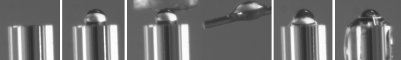
1.Introduction1.1.Current Ophthalmic Surgical TechniquesAs of 2004, 4.1 million people in the United States suffered some form of diabetic retinopathy, and that number has steadily increased each year.1 Preventive surgeries must be performed on these patients regularly to seal the leaking blood vessels on the retina. For this task, a KTP laser () and multimode optical fibers are used to create hundreds of therapeutic lesions by photocoagulation alongside a vitrectomy procedure to remove debris in the eye.2 In advanced cases, like proliferative diabetic retinopathy (PDR), the debris inside the eye settles, forming encrusted layers as well as exudate deposits on the retina. As the density of these deposits increases, especially if they form on the macular region, vision becomes greatly impaired. The current surgical procedure for PDR requires the tedious use of micro-hook needles, forceps, and other instruments to remove deposits from the retina.3 Incomplete removal of these deposits is the primary reason for retinal re-detachment and surgical failure rates. These tedious techniques create prolonged stress on the surgeon’s steadiness and the patient’s eye, allowing for errors like accidental puncture, tearing, and detachment. For these reasons, the surgical procedure for PDR, advanced retinopathy of prematurity, and other similar intraocular surgeries could benefit from an ultraprecise contact laser probe for ablation of ophthalmic tissues. Conventional fiber-optic-based surgical laser probes are designed to operate either at a fixed working distance from the tissue or in contact with the tissue with relatively large spot diameters (e.g., ). These fibers and laser probes are not widely used in intraocular laser surgery, except for thermal coagulation, because they lose their ability to focus light in aqueous media. In contrast, the novel laser probe discussed here may operate to ablate the tissue in contact mode. The highly focused beam at the probe’s surface combined with the short optical penetration depth of the erbium:YAG laser may allow better surgical results in more sensitive and thin areas like the macula, where detailed vision is achieved and surgical precision is most important. Replacement of mechanical intraocular surgical instruments with a laser probe that has a much smoother tip with a tractionless method for tissue engagement may also reduce mechanical retinal surface damage as well as retinal detachments.4 1.2.Erbium:YAG Laser for Tissue AblationThe Er:YAG laser is currently used in the medical fields of dermatology,5,6 dentistry,7,8 and ophthalmology9–15 because the 2940-nm wavelength closely matches a major water absorption peak in tissue [Fig. 1(a)], resulting in an optical penetration depth (OPD) of approximately 5 to 10 μm for soft tissues. The ablation threshold needed to achieve soft tissue removal using the Er:YAG laser is ,16 and thermal damage depths at the bottom of the ablation craters created in cornea tissue at high fluence are between 10 and 50 μm.17 In the case of PDR surgery, the Er:YAG laser’s short OPD will mean ablating the exudate deposits while minimizing thermal damage to the underlying retina, which is critical. Since most current applications of the Er:YAG laser are in dermatology and dentistry, where the tissue is readily accessible, a waveguide or fiber, although preferred, is not required to deliver the laser energy to the tissue. However, for endoscopic applications, like intraocular surgery, a specialized fiber optic delivery system is required because common silica-based fibers do not transmit beyond . Germanium oxide mid-IR fibers and hollow waveguides have been developed and tested to overcomethis issue, and they provide flexibility and high transmission. Previous studies using the Er:YAG laser during vitrectomy procedures have been reported by D’Amico, Joseph, and Hoerauf.13,18–23 These studies did not use contact probes but fibers and devices at varying distances from retinal and membrane tissue with spot sizes greater than 100 μm. Fig. 1(a) Water absorption data plotted across mid-IR wavelengths (peak absorption occurs at );24 (b) Er:YAG normal spiking mode, 75-μs pulse profile.  1.3.Surgical Laser Microprobes and MicrospheresOver the past 20 years various optical devices including spheres,25 hemispheres, domes, cones, slanted shapes,26,27 cylindrical gradient index (GRIN) lenses,28 and tapered fibers have been used as tips for ophthalmic laser scalpels. However, these devices are typically designed to operate in noncontact mode in air at a fixed working distance from the tissue. Contact mode probes can be created by placing a single sphere with a high index of refraction, between 1.7 and 2.0, at the end of a waveguide or optical fiber. Spheres at these indices will focus an incident plane wave on the back surface to a focal point near the front surface. Fast focusing through the sphere also creates a fast divergence after the sphere. This property can be used to decrease the effective penetration depth in tissue by allowing only the light near the surface of the sphere to have an energy density sufficient to ablate tissue. Working in contact mode eliminates any intervening water layer which would otherwise strongly attenuate the mid-IR laser radiation. Recently, chains of microspheres in odd multiples at these indices have been shown to reduce the spot size of the laser beam through filtering of nonperiodically focused modes (PFMs).29,30 Even-numbered spheres recollimate, whereas odd-numbered spheres refocus. Sphere chains are known to reduce transmission as the chain length increases on account of Fresnel losses and mode filtering. However, by reducing the beam size our applications also require lower laser pulse energy requirements than other fiber delivery probe devices. Furthermore, the transmission loss of a spherical lens is significantly less than a pinhole with a diameter equal to a sphere’s beam waist. The purpose of this study is to test a mid-IR laser and novel fiber optic probe for precise ablation of a thin layer of tissue, in contact mode, with minimal collateral thermal damage to underlying tissue, for potential application in ophthalmic surgeries. 2.Materials and Methods2.1.Laser Source and Fiber DeliveryAn Er:YAG laser (Model 1-2-3, Schwartz Electro-Optics, Orlando, FL) operating at a wavelength of 2940 nm, in normal-spiking mode with a pulse duration of 75 μs [Fig. 1(b)], and repetition rate of 5 Hz was used in these studies. Pulse energies of 0.02 to 1.0 mJ were used. A 2-m-long, 150-μm-core-diameter germanium oxide mid-IR optical fiber (Infrared Fiber Systems, Silver Spring, MD) was used to guide the laser energy to the scalpel. The fiber core has a refractive index of 1.84 with an attenuation of at a wavelength of 2940 nm. 2.2.Microsphere Scalpel DesignDuring preliminary studies, three types of spheres were tested to determine their candidacy for use in the surgical probe: sapphire, borosilicate, and barium titanate glass. The borosilicate glass spheres () did not focus close to the surface of the sphere because of their low index of refraction, and they also failed to provide surface focusing in longer chains. Barium titanate () provided good surface focusing but suffered from very low transmission at and also had a low damage threshold of . For our experiments we chose to use sapphire spheres with diameters of 300 and 350 μm (Swiss Jewel Company, Philadelphia, PA). Sapphire provides low attenuation at and has a refractive index of 1.71, to provide focusing near the front surface. Geometrical ray trace simulations have shown that chains of spheres with a refractive index close to 1.7 provide the smallest spatial beam width at the surface of the end sphere.31 Sapphire is also biocompatible, has a high phase transition temperature, and a high laser damage threshold. The spheres used had tight diameter tolerances and a low number of inclusions. No damage to the sapphire spheres was noticed at pulse energies up to 10 mJ. The structure of the scalpel was a semi-rigid and robust silver-lined inner diameter, outer diameter, silica hollow waveguide (HWG) (HWEA300750, Polymicro Technologies, Phoenix, AR). Current mechanical instruments used in ophthalmic surgery have overall diameters of , so our design can be easily integrated into existing surgical techniques. In these studies we used 3-cm HWGs in a straight configuration with a maximum loss of at . Since the HWG is the support structure of our probe, a length of 3 cm was determined to be the minimum length necessary to reach the retina from outside the eye, as illustrated in Fig. 2. To be a multipurpose ophthalmic scalpel used for surgeries throughout the eye, all corneal and retinal testing as well as ray trace modeling was performed under this required design constraint. Fig. 2Proposed ophthalmologic surgical configurations consisting of a 30-mm-long hollow waveguide of 0.75-mm diameter with microsphere focusing at distal tip. The diameter of a typical human eye is 24 mm.32  These waveguides provide an optical conduit, allowing insertion of the germanium oxide fiber on the proximal end and gluing of a sphere or sphere chain on the distal end. The end of the scalpel must be sealed to prevent liquid leaking into the waveguide and altering the focusing properties of the sphere chain. This was achieved by placing a slightly larger diameter end sphere of 350 μm, compared to the inner diameter of the HWG (300 μm), on the tip of the HWG and then gluing it in place with UV-cured epoxy (Norland Optical Adhesive #61, Cranbury, NJ) using micromanipulation and a small wire, as shown in Fig. 3. Additional 300-μm spheres were then inserted into the proximal end and pushed into contact with the glued sphere to create multiple-sphere structures. Our experimental setup was in a vertical orientation so the spheres inside the HWG remained in contact. Future work will be necessary to provide a more robust and permanent method of fixing the internal spheres without compromising the optical path. 2.3.Ray Tracing SimulationsSimulations of the multimode fiber output, HWG, and three different sphere configurations were modeled using Zemax (Radiant Zemax LLC, Redmond, WA). Figure 4(a) shows the light source modeled as the germanium oxide fiber’s 150-μm core with a full cone angle of 12 deg. For all presented simulations a total count of 20 million rays was used. To approximate a Gaussian distribution in the far field, a weighting factor (WF) was introduced for the irradiance of each ray, depending on its starting polar angle , where . The calculated average WF was applied in ten equally spaced angular steps from 0 to 6 deg along the cone of directions centered with the normal to the fiber surface. The rays were randomly distributed in azimuthal directions for each point source to take into account skew modes. The source was placed at the proximal opening of a 3-cm-long, 300-μm-ID HWG lined with 100% reflective walls. At the distal tip three different sphere configurations were modeled in air, as shown in Fig. 4(b). The analysis plane was placed at the minimal beam waist beyond the end sphere corresponding to our beam characterization measurements in air. 2.4.Experimental Tissue SetupFresh porcine eyes were harvested and used immediately after sacrifice of pigs from unrelated experiments. The cornea was chosen in this preliminary study as a simple model for ophthalmic tissue ablation experiments for several reasons, including its ease of use concerning dissection, preservation, processing, and analysis after laser tissue ablation. Preliminary test results performed on retinal tissue are not shown because our current capabilities hinder us from recording measurements on retinal craters. This was due to the fact that the microscopic ablation craters were difficult to distinguish visibly, and our histological fixation methods induced a large amount of stress on the fragile retina, therefore destroying the samples. The Er:YAG laser beam was coupled directly into a 2-m-long, 150-μm-core germanium oxide fiber. The fiber’s distal end was then inserted 1 mm into the proximal end of the vertically positioned 3-cm-long HWG with the glued 350-μm sphere on the bottom. Tissue ablation experiments were then performed by bringing the cornea tissue into gentle contact with the various probe configurations and translating the sample, ex vivo. The cornea was kept hydrated prior to each test by applying a single drop of Tetrahydrozoline HCl 0.05%, a common over-the-counter eye drop solution. The relatively low laser pulse rate of 5 Hz allowed creation of hundreds of single-pulse craters along this path over a period of 60 s. 3.Results3.1.Microsphere Probe Beam CharacterizationCharacterization of the probe’s beam-shaping performance was conducted before tissue studies. One-, three-, and five-sphere structures were tested to determine their relationship to spot size and transmission. Figure 5(a) and the top row of Fig. 6 show the simulation results for intensity distribution at the minimum spot size after the end sphere, from the vertex. The full width at half maximum (FWHM) measured from the simulation for each configuration of one, three, and five spheres is 8, 9, and 4 μm, respectively. For comparison, this was also measured experimentally using a 12.7-mm-focal-length calcium fluoride lens to magnify and image the minimum spot size near the sphere’s surface. An infrared beam profiler (Pyrocam III, Spiricon, Logan, UT) was positioned 50 cm from the magnification lens. To calibrate the magnification an empty HWG was used to reference 300 μm. Since the output of the multimode fiber has an unpredictable mode orientation depending on its length, bends, and coupling, the images captured by the beam profiler were averaged while gently flexing the fiber near its mid-length point. This motion generated random mode orientation patterns hitting the sphere chains, thus creating repeatable profile measurements. The averaged FWHM beams measured for one, three, and five spheres were 67, 32, and 30 μm, respectively, with representative beam profiles shown in Fig. 5(b). Fig. 5(a) Normalized simulation of the intensity measured at the minimum beam waist (FWHM) for one-, three-, and five-sphere configurations. (b) Three-dimensional beam profiles acquired by magnifying the minimum beam waist onto the IR beam profiler’s detector array. As the number of spheres increase, a reduction in FWHM spot diameter and an expanding low intensity mode-filtering ring can be seen in both simulation and experiment.  Fig. 6(top row) Simulated intensity profiles for one-, three-, and five-sphere probes at minimum spot size occurring at 10 μm after sphere vertex. (middle row) Representative bird’s eye corneal crater images for one-, three-, and five-sphere probes at 0.1 mJ. (bottom row) Representative histology images for one-, three-, and five-sphere probe craters at 0.1 mJ with trichrome stain.  3.2.Ablation Crater Measurements on Cornea TissueVarious pulse energies between 0.02 and 1.0 mJ at a duration of 75 μs were tested to experimentally determine the ablation threshold of the cornea. With an average FWHM beam diameter of , craters began to form at a pulse energy of 0.1 mJ corresponding to an energy density of . Single-pulse craters were formed on hydrated cornea tissue using this near-threshold pulse energy of 0.1 mJ. Pulse energy was measured with a pyroelectric detector (ED-100A, Gentec, Saint-Foy, Canada) near the tip of the probe. Single-, three-, and five-sphere structures were tested, and the tissue was imaged and measured with an FS70 Mitutoyo microscope equipped with a CCD camera (Edmund Optics, Barrington, NJ). Since each sphere chain configuration (one, three, or five spheres) attenuated the energy differently, attenuation of the laser output was adjusted to normalize each configuration to an incident energy of 0.1 mJ on the tissue surface. Over 50 craters for each structure were measured, and the average crater widths are shown in Table 1 along with representative images for each in Fig. 6. Table 1Corneal ablation crater dimensions at pulse energies of 0.1 mJ (S.D.=10 μm).
Histologic analysis was performed on the corneas to quantify ablation crater and thermal damage depths. The crater diameters were measured by light microscopy immediately after the procedure, and then the eyes were placed in formalin. Eyes were sectioned and the extra material was discarded, leaving only the polar cornea region. The corneas were trimmed for histological processing, and various samples were stained with either trichrome or hematoxylin-eosin. The craters were viewed and measured with the Mitutoyo microscope. Over 10 trichrome-stained histology craters for each structure were measured, and the average crater depths are shown in Table 1 along with representative images for each shown in Fig. 6. 4.DiscussionShort ablation depths with small thermal damage regions have been achieved with Er:YAG laser probes in previous studies.13,17–23 However, our contact-mode mid-IR microsphere scalpel can create spatially small ablation craters below the limit of current intraocular fiber delivery systems, while using a less powerful laser source. Sapphire microspheres with a refractive index of 1.71, used as lenses, focus laser light at the sphere’s surface, creating a robust contact laser device whose performance is unaffected by the transmission medium. By building these sphere chains inside an air-filled hollow waveguide’s tip and sealing it to the end sphere, all internal focusing surfaces maintain their relative refractive indices even when submerged in the vitreous. The overall energy output decreases with increasing number of spheres due to nonPFM filtering. This can be seen by examining the output beam profiles of each sphere structure, as shown in Fig. 5(b). However, the FWHM spot diameter decreases and the peak energy only slightly decreases. Fresnel equations predict an decrease for every odd-numbered sphere or four sapphire/air interfaces, which is confirmed in our testing. The low intensity region around the central peak, seen in the three- and five-sphere chain, is believed to be due to the mode filtering (Fig. 5). It is important to realize that the simulations represent an ideal case of perfectly aligned spheres and fiber output on one axis as well as defect-free materials. Geometrical modeling of sphere lenses shows that they can produce a or sometimes larger for chains, and therefore all the rays cannot be captured by our imaging system (Fig. 7). This means that the FWHM measurements stated earlier only show what is occurring in the on-axis cone , which corresponds to our magnification lens. This could also explain why the low intensity region in the five-sphere beam profile is not visible in Fig. 5(b) but is in Fig. 5(a) because the rays were so off-axis they were not captured by the imaging system. Future work will be conducted to fully capture and characterize the beam exiting the sphere structures. The slight lean of each peak can be explained by the spheres inside the HWG not being perfectly aligned on-axis and the fiber tip not perfectly centered and aligned in the input end of the HWG. Fig. 7Beam characterization of the microsphere probe using a magnification lens to focus the minimum waist onto the infrared beam profiler’s detector array 50 cm away. Rays beyond the numerical aperture of the lens were not captured experimentally but are present in simulations and tissue testing since the device operates in contact mode with tissue.  Comparable to the characterization, the ablation crater widths in corneal tissue decreased on average with increasing chain lengths. However, by visual inspection the lateral thermal damage regions increased (Fig. 6). One cause for this larger thermal region may be the filtered nonPFMs, which create a low intensity region. The lower intensity region visible in the three-sphere beam profile [Fig. 5(b)] is below the ablation threshold but is still sufficient to create thermal damage. The numerical aperture or angle of the rays exiting the end sphere also increases with increasing sphere chains, spreading the energy over a larger area and decreasing the energy density once the rays leave the scalpel and enter the tissue. These filtered modes and increasing angles cause the five-sphere chain to cause even greater thermal damage as seen in Fig. 6. Ablation crater depths on corneal tissue were measured between 10 and 25 μm (Table 1 and Fig. 6). While retinal tissue has different optical and mechanical properties than cornea, by using the Er:YAG laser, which has such a strong water absorption peak, future retinal tissue ablation results may be comparable. Removal of small deposits with thicknesses between 20 and 50 μm on top of the retina, while minimizing damage to the retina which has a thickness ranging between 150 and 300 μm, is the primary goal of this scalpel design. Average ablation crater depth for each structure decreased with an increase in sphere chain length. However, the thermal damage zones increased for multiple-sphere chains. The numerical aperture of the rays entering the tissue may be responsible for this result because the gradual spreading of these rays increases the lateral thermal damage. This could also explain the increase in thermal depth for three spheres and then the decrease in depth for five spheres. The three spheres did not have sufficient perpendicular directionality to ablate deeper than one sphere, but still had steeper angles than the five-sphere structures to direct the thermal depths deeper. Instead, the five-sphere chain, which had the highest numerical aperture, directed the energy more laterally from the sphere tip. In the single-sphere case the beam is more normal and therefore directs the energy deeper, ablating more tissue with less, if any, noticeable thermal damage. These average thermal damage trends were noticed in almost all histology craters examined. Multiple-sphere chains result in a more diverging beam at the sphere tip and spread the same, normalized energy over a larger volume after entering the tissue, decreasing ablation and increasing thermal damage. In all samples measured, including other studies with higher pulse energies greater than 0.2 mJ, three- and five-sphere structures always showed more thermal damage. Further simulations involving tissue scattering/absorption modeling will need to be performed in future studies to provide a more detailed explanation of these findings. Several improvements can be made to the probe design. Modeling has shown that the spot size will decrease if the sphere diameters are reduced and if all the spheres are the same diameter, including the end sphere.31 We chose a slightly larger end sphere for this study for its ease of assembly, but it should be possible to fix and seal a smaller sphere at the HWG tip with more precise methods. Also for a practical device the internal spheres will have to be fixed in some way. Work is also being done to further reduce the spot size by improving the input beam profile. Single-mode germanium oxide fibers or other waveguides optimized for 2940 nm are not currently available, as these would be ideal for delivering the smallest spot sizes and improved spatial beam profiles. Preliminary testing has demonstrated a factor of six size reduction compared to FWHM sizes reported in Fig. 5(b) for same structures with near-single-mode input beams. However, to accomplish this task for a practical application, the laser output must be directly applied to the sphere structures. Although not observed or characterized in this preliminary study with corneal tissues, it is possible that exploding and imploding vapor bubbles at the treatment site may result in mechanical damage to other more delicate ophthalmic tissues of interest, such as the retina, which do not have the same robust mechanical properties as the cornea. We believe that these bubbles are highly localized and shallow and therefore will not cause significant mechanical tissue damage on account of the low pulse energy, small spot diameter, and contact mode application of our probe. However, further detailed studies utilizing a high-speed camera to directly image the cavitation bubble dynamics during mid-IR ablation of both corneal and retinal tissues will be necessary in future work to confirm these claims. Regardless, water is still the primary absorber at the mid-IR wavelength of 2.94 μm for both tissues, so the optical properties of the tissues should be more similar than the mechanical properties. Finally, this probe design should be easily translatable from an air environment described in these preliminary studies with the corneal samples to a fluid environment utilizing retinal tissue for potential PDR applications since the device works in contact mode and is watertight. 5.ConclusionsA 750-μm-outer-diameter intraocular scalpel utilizing microsphere lenses was developed that is capable of delivering Er:YAG laser pulse energy to ocular tissue and creating ablation craters with widths between 15 and 50 μm in contact mode. Different scalpel configurations with varying sphere chain lengths were successfully simulated and tested under ex vivo conditions on corneal tissue near the ablation threshold, demonstrating ablation crater size reduction for increasing number of microspheres, but with an increase in thermal damage. The small spatial beam size combined with the short optical penetration depth of less than 20 μm could make this probe useful for precise contact ablation of exudates during surgery for PDR. Future studies will involve further development of the microsphere probe and in vivo studies in a PDR animal model. AcknowledgmentsThis research was supported by the National Institutes of Health under Grant R41EY019598. The simulation work was supported by the U.S. Army Research Office through Dr. J. T. Prater under Contract W911NF-09-1-0450 and by the National Science Foundation under Grant ECCS-0824067. The authors thank Cliff Williams and Mike Quinn from Carolinas Medical Center for providing the porcine eyes, Eric Smith from Celligent Technologies for processing the samples for histology, and MO-SCI Corporation for donating microspheres for this work. The content is solely the responsibility of the authors and does not necessarily represent the official views of the organizations funding this work. References
“The prevalence of diabetic retinopathy among adults in the United States,”
Arch. Ophthalmol., 122
(4), 552
–563
(2004). http://dx.doi.org/10.1001/archopht.122.4.552 AROPAW 0003-9950 Google Scholar
J. M. Krauss and C. A. Puliafito,
“Lasers in ophthalmology,”
Lasers Surg. Med., 17
(2), 102
–159
(1995). http://dx.doi.org/10.1002/(ISSN)1096-9101 LSMEDI 0196-8092 Google Scholar
G. L. Spaeth, Ophthalmic Surgery: Principles and Practice, W. B. Saunders, Philadelphia, USA
(1982). Google Scholar
J. W. Berger and D. J. D’Amico,
“Modeling of erbium: YAG laser-mediated explosive photovaporization: implications for vitreoretinal surgery,”
Ophthalmic Surg. Lasers, 28
(2), 133
–139
(1997). 1082-3069 Google Scholar
R. Kaufmann,
“Role of the erbium:YAG laser in the treatment of aged skin,”
Clin. Exp. Dermatol., 26
(7), 631
–636
(2001). http://dx.doi.org/10.1046/j.1365-2230.2001.00896.x CEDEDE 1365-2230 Google Scholar
T. S. Alster and J. R. Lupton,
“Er:YAG cutaneous laser resurfacing,”
Dermatol. Gun., 19
(3), 453
–466
(2001). Google Scholar
P. Rechmann, D. S. Glodin and T. Hennig,
“Er:YAG lasers in dentistry: an overview,”
Proc. SPIE, 3248 2
–13
(1998). http://dx.doi.org/10.1117/12.306009 PSISDG 0277-786X Google Scholar
D. M. Clarkson,
“A review of technology and safety aspects of erbium lasers in dentistry,”
Dent. Update, 28
(6), 298
–302
(2001). 0305-5000 Google Scholar
A. Ozler et al.,
“Infrared laser sclerostomies,”
Invest. Ophthalmol. Vis. Sci., 32
(9), 2498
–2503
(1991). IOVSDA 0146-0404 Google Scholar
R. A. Hill et al.,
“Laser trabecular ablation (LTA),”
Lasers Surg. Med., 11
(4), 341
–346
(1991). http://dx.doi.org/10.1002/(ISSN)1096-9101 LSMEDI 0196-8092 Google Scholar
M. L. McHam et al.,
“Erbium:YAG laser trabecular ablation with a sapphire optical fiber,”
Exp. Eye Res., 65
(2), 15
–155
(1997). http://dx.doi.org/10.1006/exer.1996.0274 EXERA6 0014-4835 Google Scholar
Jr. G. Stevens et al.,
“Erbium:YAG laser-assisted cataract surgery,”
Ophthalmic Surg. Lasers, 29
(3), 185
–189
(1998). 1082-3069 Google Scholar
P. D. Brazitkos et al.,
“Experimental ocular surgery with a high-repetition-rate erbium:YAG laser,”
Invest. Ophthalmol. Vis. Sci., 39
(9), 1667
–1675
(1998). IOVSDA 0146-0404 Google Scholar
C. C. Neubaur and Jr. G. Stevens,
“Erbium:YAG laser cataract removal: role of fiber-optic delivery system,”
J. Cataract Refract. Surg., 25
(4), 514
–520
(1999). http://dx.doi.org/10.1016/S0886-3350(99)80048-0 0886-3350 Google Scholar
T. Wesendahl et al.,
“Erbium:YAG laser ablation of retinal tissue under perfluorodecaline: determination of laser-tissue interaction in pig eyes,”
Invest. Ophthalmol. Vis. Sci., 41
(2), 505
–512
(2000). IOVSDA 0146-0404 Google Scholar
U. Hohenleutner et al.,
“Fast and effective skin ablation with and Er:YAG laser: Determination of ablation rates and thermal damage zones,”
Laser Surg. Med., 20
(3), 242
–247
(1997). http://dx.doi.org/10.1002/(ISSN)1096-9101 0196-8092 Google Scholar
J. T. Walsh, T. J. Flotte and T. F. Deutsch,
“Er:YAG laser ablation of tissue: effect of pulse duration and tissue type on thermal damage,”
Lasers Surg. Med., 9
(4), 314
–326
(1989). http://dx.doi.org/10.1002/(ISSN)1096-9101 LSMEDI 0196-8092 Google Scholar
D. J. D’Amico et al.,
“Initial clinical experience with an erbium:YAG laser for viteoretinal surgery,”
Am. J. Opthalmol., 121
(4), 414
–425
(1996). 0002-9394 Google Scholar
D. J. D’Amico et al.,
“Multicenter clinical experience using an erbium:YAG laser for vitreoretinal surgery,”
Ophthalmology, 103
(10), 1575
–1585
(1996). OPANEW 0743-751X Google Scholar
D. P. Joseph et al.,
“A new and improved vitreoretinal erbium:YAG laser scalpel: long term morphologic characteristics of retinal-choriodal injury,”
Ophthalmic Surg. Lasers Imag., 35
(4), 304
–315
(2004). 1542-8877 Google Scholar
M. H. Krause and D. J. D’Amico,
“Ablation of vitreous tissue with a high repetition rate erbium:YAG laser,”
Eur. J. Ophthalmol., 13
(5), 424
–432
(2003). EJOOEL 1120-6721 Google Scholar
H. Hoerauf et al.,
“Retinal photoablation with the erbium:YAG laser, initial experimental results for traction-free removal of tissue,”
Ophthalmologe, 100
(2), 115
–121
(2003). http://dx.doi.org/10.1007/s00347-002-0722-x 0941-293X Google Scholar
H. Hoerauf et al.,
“Photoablation of inner limiting membrane and inner retinal layers using the erbium:YAG laser: an in vitro study,”
Lasers Surg. Med., 38
(1), 52
–61
(2006). http://dx.doi.org/10.1002/(ISSN)1096-9101 LSMEDI 0196-8092 Google Scholar
G. M. Hale and M. R. Querry,
“Optical constants of water in the 200 nm to 200 um wavelength region,”
Appl. Opt., 12
(3), 55
–563
(1973). http://dx.doi.org/10.1364/AO.12.000555 APOPAI 0003-6935 Google Scholar
R. M. Verdaasdonk and C. Borst,
“Ray tracing of optically modified fiber tips, 1: spherical probes,”
Appl. Opt., 30
(16), 2159
–2171
(1991). http://dx.doi.org/10.1364/AO.30.002159 APOPAI 0003-6935 Google Scholar
K. Iwai et al.,
“Penetration of high-intensity Er:YAG laser light emitted by IR hollow optical fibers with sealing caps in water,”
Appl. Opt., 43
(12), 2568
–2571
(2004). http://dx.doi.org/10.1364/AO.43.002568 APOPAI 0003-6935 Google Scholar
T. Watanabe and Y. Matsuura,
“Side-firing sealing caps for hollow optical fibers,”
Lasers Surg. Med., 38
(8), 792
–797
(2006). http://dx.doi.org/10.1002/(ISSN)1096-9101 LSMEDI 0196-8092 Google Scholar
D. X. Hammer et al.,
“Intraocular laser surgical probe for membrane disruption by laser-induced breakdown,”
Appl. Opt., 36
(7), 1684
–1693
(1997). http://dx.doi.org/10.1364/AO.36.001684 APOPAI 0003-6935 Google Scholar
A. M. Kapitonov and V. N. Astratov,
“Observation of nanojet-induced modes with small propagation losses in chains of coupled spherical cavities,”
Opt. Lett., 32
(4), 409
–411
(2007). http://dx.doi.org/10.1364/OL.32.000409 OPLEDP 0146-9592 Google Scholar
S. Yang and V. N. Astratov,
“Photonic nanojet-induced modes in chains of size-disordered microspheres with an attenuation of only 0.08 dB per sphere,”
Appl. Phys. Lett., 92
(26), 261111
(2008). http://dx.doi.org/10.1063/1.2954013 APPLAB 0003-6951 Google Scholar
A. Darafsheh et al.,
“Contact focusing multimodal microprobes for ultraprecise laser tissue surgery,”
Opt. Express, 19
(4), 3440
–3448
(2011). http://dx.doi.org/10.1364/OE.19.003440 OPEXFF 1094-4087 Google Scholar
L. A. Remington, Clinical Anatomy of the Visual System, 10 2nd ed.Elsevier Butterworth Heinemann, Philadelphia, PA
(2005). Google Scholar
|