|
|
1.IntroductionDuring the past decade, developments in quantitative phase imaging techniques have provided insights into the dynamic processes in unstained living cells with fast acquisition rates and unprecedented accuracies. These techniques translate the phase information of the light wave, which has interacted with the sample and cannot be measured directly, to intensity variations that can be recorded by conventional detectors. Unlike conventional differential interference contrast (DIC) or phase contrast microscopy, which are inherently qualitative, quantitative phase microscopy allow measuring of optical path delay (OPD) and topographic data of a single point or full-field images.1–4 Since RBCs lack a nucleus, a constant refractive index can be assumed on the entire cell viewable area. Therefore, the RBC OPD profile measured by quantitative phase microscopy is proportional to the thickness profile of the RBC.5 RBC membrane fluctuations can be detected using the time-dependent thickness profile of the RBC, and cell membrane stiffness properties can be calculated from these data. Thus, quantitative phase microscopy yields biologically-relevant parameters of live RBCs which can be used as a powerful tool for research and diagnosis.6,7 The elastic properties of RBCs, defining their deformability, are dependent on the bending and shearing properties of the cell membrane, which are governed mostly by metabolically regulated coupling between the lipid bilayer and the underlying spectrin-actin cytoskeletal network.8–10 The membrane fluctuation amplitude, reflecting the bending and shearing of the membrane, was shown to be directly related to RBC deformability.11 RBC deformability is vital as it enables the RBC to squeeze through the small body capillaries which are only several micrometers in size. Certain pathological conditions in RBCs, such as spherocytosis, malaria, and sickle cell disease, affect the flexibility of the cells as well as change their dynamic behavior and might hinder the efficacy of oxygen transportation to the tissues. These effects were previously studied using qualitative and quantitative techniques.6–8 Optical coherence microscopy (OCM)12 is an imaging technique that is capable of recording of the amplitude and the phase information of the light that has interacted with single or multiple cells. A typical OCM system records the interference pattern between the light that has interacted with the sample and a reference wave, where the light source used is a low-coherence source. In time-domain OCM, the reference arm pathlength is scanned and an internal reflectivity profile of the sample is constructed. In spectral-domain OCM, the spectral density of the interference pattern is captured and a Fourier analysis is used to reconstruct the internal sample reflectivity profile. For phase imaging, spectral-domain OCM offers several advantages over the time-domain OCM. For a single-point measurement, spectral-domain OCM can have no mechanical moving parts resulting in decreased phase noise. In addition, it can be built using a common-path geometry in which all common components of the phase noise between the reference and sample beams are eliminated. Full-field interferometric measurements of RBCs are frequently based on the principles of digital holographic microscopy.5–7,13–16 In this technique, spatial interferograms are collected from an area which includes many points. These interferograms are processed into the two-dimensional phase profiles of the sample, which are suitable for recording both spatially- and time-dependent phenomena. However, digital holographic microscopy usually uses separate interferometer arms, yielding higher degree of noise or, if used in common-path, on-axis geometry, it requires several frames of acquisition for each instance of the sample, which is not suitable for highly-dynamic samples. In addition, the energy of the light source is spread over a larger area, further reducing the signal to noise (SNR) ratio. Therefore, this full-field interferometric technique has inherently lower SNR compared to a single-point interferometric technique. In single-point interferometric measurements of live cells,17,18 the light is focused on a small area and therefore higher irradiance allows for ultrafast acquisition rates with compact and reasonable-price detectors. Furthermore, single-point measurements also allow for an easy-to-implement common-path geometry, as well as a compact and portable fiber-optics configuration, and thus can work even without using floating optical tables, which presents a significantly higher potential for clinical applications. In this paper, we present the spectral-domain phase microscopy (SDPM) system, which is based on an OCM principle, to realize a compact, portable and yet high-accurate technique for quantitatively measuring the RBC membrane dynamics, with the potential for future clinical applications of high-accuracy blood screening. We experimentally demonstrate the SDPM ability to measure RBCs with significantly decreased amplitude of membrane fluctuations, demonstrating the superior properties of SDPM in measuring RBCs compared to a full-field interferometric technique. 2.SDPM PrinciplesSchematic diagram of the SDPM system is shown in Fig. 1. A super-luminescent diode (SLD) (Superlum, central wavelength 840 nm, FWHM spectrum bandwidth of 50 nm, 15 mW fiber output power) light passes through a polarization controller and is split using a fiber coupler. One of the outputs from the coupler is collimated using a spherical lens with 5-cm focal length, and focused onto the sample using a microscope objective, yielding a transverse resolution limit of approximately 0.6 μm. The sample is placed in a closed chamber such that the reflection from the upper surface of the chamber is used as the reference beam and the light reflected from the bottom surface, after passing through the cells and the media, is used as the sample beam. To increase the bottom surface reflection and thus improve the SNR, we used sputter deposition to coat the bottom glass surface by a thin layer of chrome for adhesion, and then by additional layer of gold over it creating an inert reflective surface. The combined reference and sample beams pass back through the fiber coupler to a compact spectrometer (Ocean Optics , 2048 pixel CCD, spectral range 718 to 900 nm, best efficiency 650 to 1100 nm) where the interference pattern is recorded. As shown in Fig. 1, to be able to locate the object of interest, a compact digital camera arm was added to the system. The camera arm consists of a 15-cm focal-length spherical tube lens and a compact CMOS camera (Thorlabs, monochrome CMOS camera, with of each). The tube lens and the objective lens are in 4f configuration. The camera displays the SLD beam and the bright field sample image simultaneously, and allows the correct positioning of the SLD beam over the chosen RBC (see Fig. 2). Fig. 1Schematic diagram of the SDPM system. The blood sample is encapsulated between two partially-reflecting surfaces. 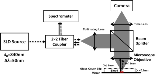 Fig. 2Intensity image captured by the camera. The SLD spot is focused on an area approximately half way between the cell center and cell outer rim. 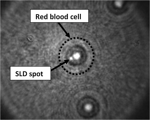 To retrieve the phase information, we used the windowed Fourier transform method.17,19–21 The intensity of the interference pattern on the spectrometer can be expressed as follows: where is the wavenumber, is the spectral density of the SLD, and are the reflectivities from the top (reference) and the bottom surfaces, respectively, is the OPD between the sample and the reference signals, and is a constant phase shift.To retrieve the OPD, a Fourier transform was performed on the spectral data giving the depth space. A Gaussian band-pass filter was then applied on the positive term of the complex depth function to remove noise and unwanted reflections. Then, an inverse Fourier transform was applied returning to wavenumber space and giving the complex expression: The phase term can be retrieved as follows: The system sensitivity in time depends on the stability of the phase expression in Eq. (3). To determine the OPD without ambiguities, the phase function needs to be unwrapped. First, a least-square algorithm is used to determine the slope of the phase as a function of the wavelength. Then, the slope of the phase function is used as the reference to remove ambiguities, and one phase component is chosen to give the absolute OPD as follows: where is the phase that was retrieved from the slope of the phase function. In phase measurements with Fourier-domain OCM, the oscillations of the fringes in the spectral domain due to the OPD between the reference and sample beams are detected. Since the phase oscillates rad at every shift of half a wavelength of the OPD, high-sensitivity phase measurements of the fringes can provide an ultrahigh-accuracy measurement of the change in the OPD.173.Experimental MethodsTo demonstrate the system ability to measure live-cell fluctuations, we used healthy RBCs as well as RBCs treated with glutaraldehyde at various concentrations. Glutaraldehyde causes cross-linking of proteins, mostly cell-surface proteins, leading to more rigid structures and thus stiffens the RBC membrane and diminishes fluctuation amplitudes.22 By studying these low-amplitude membrane fluctuations, we demonstrated that our system is more sensitive than many commonly-used quantitative phase measurement systems, such as those based on wide field digital interferometry (WFDI), a digital holographic microscopy approach. 3.1.SDPM SystemWe constructed the system shown in Fig. 1 and described in Sec. 2. On a non-floating table, our SDPM system has remarkable OPD stability of 690 pm in a liquid environment. This stability was found to be better than the stability achieved with our WFDI system even on a floating table. On an isolated floating table, the SDPM had an OPD stability of 300 pm in a liquid environment, more than three times better than WFDI under the same conditions. To verify the SDPM system calibration, we used it to measure the thickness at the center of a polymer microsphere (Thermo Scientific Monosized Polymer, with manufacturer size distribution of ). For a refractive index of 1.576 at 840 nm wavelength, the SDPM system measured microsphere thickness of 4.972 μm (which is within the size distribution declared by the manufacturer) with temporal SDPM stability of 0.32 nm. To measure the time behavior of RBCs using SDPM, the SLD beam was focused on the highest point of the cell torus, located approximately half-way between the outer cell rim and the cell center, as shown in Fig. 2. RBCs vibrate at rates of 0.3 to 30 Hz.11 We demonstrated our system capabilities by collecting the spectral data at 20 Hz with an integration time of 1 ms for a period of 30 s. To obtain the change in the cell thickness , the change in the cell OPD is divided by the index of refraction difference between the media and the RBC: where is the difference in the index of refraction between the RBC and the surrounding media. The indices of refraction were assumed to be 1.395 for the RBC and 1.33 for the media.6 As the fluctuations in cell thickness are within the ambiguity, Eq. (3) was used without the need to apply unwrapping.3.2.WFDI SystemThe WFDI setup is based on a modified Mach-Zander interferometer.23 The two systems (SDPM and WFDI) were built on the same table. For WFDI, phase measurements were collected simultaneously from a region containing several RBCs. The system produces a phase image with a field of view of . We recorded at a framerate of 20 Hz for 30 s, with an exposure time of 1 ms. Data were spatially averaged using a 2-D Gaussian to obtain a similar lateral resolution as that of the SDPM system. Data was taken in each RBC from a region of approximately the same area as that of the SLD in SDPM. The cell thickness change is found using Eq. (5). 3.3.RBC PreparationsFresh human blood was obtained from healthy volunteers by a fingerprick. The blood was diluted by phosphate buffered saline without Ca and Mg, supplemented with 10 mM glucose (PBSG solution) and RBCs were separated by centrifugation at 1000 rpm for 10 min at 4°C. After removing of buffy coat, RBCs were washed twice with PBSG at 2000 rpm for 3 min. The cells were then resuspended in PBSG solution supplemented with 0.9 mM , 0.5 mM and bovine serum albumin. RBC suspension was then introduced into the experimental chamber, placed on the mirror-coated slide and left for 15 min. to allow adhesion of the cells to the gold surface. Afterwards, the cells in the chamber were washed with PBSG and examined by SDPM or WFDI. Alternatively, the solution in the chamber, after washing the cells with PBSG, was exchanged with PBSG solution containing 1 m Methylene glycol tetraacetic acid and glutaraldehyde at five different concentrations: 0.001%, 0.0025%, 0.005%, 0.025%, and 2.5%. After 15 min. of incubation at room temperature the cells in the chamber were washed with the PBSG solution to remove glutaraldehyde from the bath solution. 4.Measurements and ResultsIn both systems, data were collected from 10 healthy RBCs (control) and 10 RBCs treated with each of the five glutaraldehyde concentrations. During measurements, the temperature was monitored and maintained at . To determine system OPD stability, signal from an area outside the cells (through media only) was recorded for each concentration for 30 s. Fluctuations of cell thickness at the chosen point on the cell over a 30-s time frame for a typical RBC are shown for each concentration in Fig. 3. The membrane fluctuations gradually decrease at higher concentrations of glutaraldehyde, as could be expected, due to the cross-linking of proteins on the membrane surface. The amplitude of fluctuations in healthy RBCs can be as high as 140 nm, whereas for the 0.025% glutaraldehyde-treated RBCs, the maximal amplitude was roughly 45 nm. Fig. 3Unbiased membrane displacement as measured by the SDPM system is plotted for a typical RBC in each of the glutaraldehyde concentrations over a time period of 30 s. In each graph the noise measured in an area with media only is plotted as well to show the system sensitivity: (a) Control – no glutaraldehyde; (b) Glutaraldehyde 0.001%; (c) Glutaraldehyde 0.0025%; (d) Glutaraldehyde 0.005%; (e) Glutaraldehyde 0.025%; (f) Glutaraldehyde 2.5% (visibly dead RBCs). 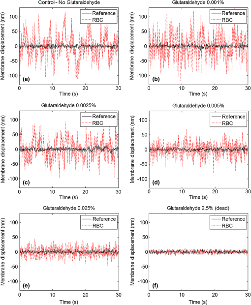 The standard deviation (STD) of the membrane displacements over 30 s was calculated for each RBC. As shown in Fig. 4, both SDPM and WFDI systems show similar membrane displacement behaviors at the lower concentrations of glutaraldehyde. For normal untreated RBCs, the membrane displacement STD was found to be . As the concentration levels of glutaraldehyde increase, the displacement STD decreases: at 0.001%, at 0.0025%, at 0.005%, and at 0.025%. At 0.005% glutaraldehyde concentration, about 50% of the RBCs showed echinocyte morphology, and only cells that preserved regular discocyte shape were accounted. Some of the RBC displacements were just above the measurable levels for the WFDI system. Fig. 4Membrane displacement values of ten RBCs from both systems SDPM and WFDI for different glutaraldehyde concentrations. Each shape represents a single cell membrane displacement STD over a 30-s time period. The horizontal line is the average value of each group. 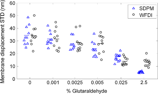 At a 2.5% concentration, the RBC membrane fluctuation amplitude further decreased so that OPD measurements of these cells and the measurements on an area outside the cells with the media only were similar. SDPM had OPD stability of about 300 pm (which translates to an approximate 4.5-nm membrane displacement) compared to 900 pm (which translates to an approximate 14-nm membrane displacement) for the WFDI system. SDPM was sensitive enough to detect fluctuations at 0.025% glutaraldehyde concentration. WFDI, however, was not capable to detect those fluctuations due to lower sensitivity levels than the SDPM system. The membrane equivalent elastic constant was calculated for SDPM as follows: where is the Boltzmann constant, is the ambient temperature, and is the mean squared displacement. For normal RBC, the elastic constant was found to be . As shown in Fig. 5, up to at least 0.005% glutaraldehyde, the elastic constant exhibited linear behavior of approximately . Up to 2.5% concentration, the behavior is approximately exponential with a slope of .Fig. 5Membrane equivalent elastic constant for different glutaraldehyde concentrations averaged over all the cells in the group: (a) Reduced range of glutaraldehyde concentrations (0 to 0.005%), linear scales; (b) Expanded range of glutaraldehyde concentrations (0.001 to 2.5%) at log-log scale. 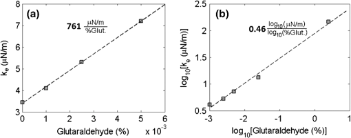 These results demonstrate how elasticity changes in the membrane of RBCs manifest in temporal behavior changes. Analyzing these changes clearly shows a difference between healthy RBCs and glutaraldehyde-treated RBCs. These changes were well recorded with both systems up to 0.005% concentration with similar results. The membrane displacements, even as low as 18 nm at 0.025% concentration, were at least three times higher than the minimum detectable displacement of the SDPM system, whereas these displacements were just at the detectable threshold of the WFDI system. The higher degree of SNR in the SDPM system is expected to enable measuring lower membrane fluctuations characterizing various diseases such as sickle cell anemia7 and malaria.6 5.ConclusionsWe presented the SDPM, a simple, compact, and low-cost quantitative phase measurement technique with 0.3 nm OPD sensitivity in a liquid environment. The sensitivity surpassed that of WFDI-based quantitative phase measurement technique by a factor of approximately 3 under the same experimental conditions. In spite of the fact that multiple points of measurement can be provided by WFDI, the higher-sensitivity single point measurements that can be provided by the more-compact SDPM system might be enough for diagnosis purposes. In addition, the stability of the SDPM system due to its common-path geometry means that it can be built on a non-floating table and still obtain high stability. Furthermore, the reflection geometry as well as its compactness and portability give the proposed system a high potential for clinical applications. AcknowledgmentsThis study was supported by the Israel Science Foundation (ISF) Bikura Grant. We thank Dr. Yizheng Zhu for helpful discussions during the initial steps of the research. ReferencesC. Yanget al.,
“Phase-referenced interferometer with subwavelength and subhertz sensitivity applied to the study of cell membrane dynamics,”
Opt. Lett., 26
(16), 1271
–1273
(2001). http://dx.doi.org/10.1364/OL.26.001271 OPLEDP 0146-9592 Google Scholar
M. A. Chomaet al.,
“Spectral-domain phase microscopy,”
Opt. Lett., 30
(10), 1162
–1164
(2005). http://dx.doi.org/10.1364/OL.30.001162 OPLEDP 0146-9592 Google Scholar
N. T. ShakedM. T. RinehartA. Wax,
“Dual-interference-channel quantitative-phase microscopy of live cell dynamics,”
Opt. Lett., 34
(6), 767
–769
(2009). http://dx.doi.org/10.1364/OL.34.000767 OPLEDP 0146-9592 Google Scholar
Z. Wanget al.,
“Spatial light interference microscopy (SLIM),”
Opt. Exp., 19
(2), 1016
–1026
(2011). http://dx.doi.org/10.1364/OE.19.001016 OPEXFF 1094-4087 Google Scholar
G. Popescuet al.,
“Imaging red blood cell dynamics by quantitative phase microscopy,”
Blood Cell. Mol. Dis., 41
(1), 10
–16
(2008). http://dx.doi.org/10.1016/j.bcmd.2008.01.010 1079-9796 Google Scholar
Y. Parket al.,
“Refractive index maps and membrane dynamics of human red blood cells parasitized by Plasmodium falciparum,”
PNAS, 105
(37), 13730
–13735
(2008). http://dx.doi.org/10.1073/pnas.0806100105 PNASA6 0027-8424 Google Scholar
N. T. Shakedet al.,
“Quantitative microscopy and nanoscopy of sickle red blood cells performed by wide field digital interferometry,”
J. Biomed. Opt. Lett., 16
(3), 030506
(2011). http://dx.doi.org/10.1117/1.3556717 JBOPFO 1083-3668 Google Scholar
S. Tuviaet al.,
“Mechanical fluctuations of the membrane–skeleton are dependent on F-Actin ATPase in human erythrocytes,”
J. Cell Biol., 141
(7), 1551
–1561
(1998). http://dx.doi.org/10.1083/jcb.141.7.1551 JCLBA3 0021-9525 Google Scholar
L. C. -L. LinN. GovF. L. H. Brown,
“Nonequilibrium membrane fluctuations driven by active proteins,”
J. Chem. Phys., 124
(7), 074903
(2006). http://dx.doi.org/10.1063/1.2166383 JCPSA6 0021-9606 Google Scholar
K. ZemanH. EngelhardE. Sackmann,
“Bending undulations and elasticity of the erythrocyte membrane: effects of cell shape and membrane organization,”
Eur. Biophys. J., 18
(4), 203
–219
(1990). http://dx.doi.org/10.1007/BF00183373 EBJOE8 0175-7571 Google Scholar
S. Tuviaet al.,
“-Adrenergic agonists regulate cell membrane fluctuations of human erythrocytes,”
J. Physiol., 516
(3), 781
–792
(1999). http://dx.doi.org/10.1111/tjp.1999.516.issue-3 JPHYA7 0022-3751 Google Scholar
J. A. IzattM. A. Choma,
“Theory of optical coherence tomography,”
Optical Coherence Tomography: Technology and Applications, 47
–72 Springer, London, UK
(2008). Google Scholar
B. Rappazet al.,
“Spatial analysis of erythrocyte membrane fluctuations by digital holographic microscopy,”
Blood Cell. Mol. Dis., 42
(3), 228
–232
(2009). http://dx.doi.org/10.1016/j.bcmd.2009.01.018 1079-9796 Google Scholar
I. Bernhardtet al.,
“Application of digital holographic microscopy to investigate the sedimentation of intact red blood cells and their interaction with artificial surfaces,”
Bioelectrochemistry Amsterdam Netherlands, 73
(2), 92
–96
(2008). http://dx.doi.org/10.1016/j.bioelechem.2007.12.001 BIOEFK 1567-5394 Google Scholar
R. Liuet al.,
“Recognition and classification of red blood cells using digital holographic microscopy and data clustering with discriminant analysis,”
J. Opt. Soc. Am. A, 28
(6), 1204
–1210
(2011). http://dx.doi.org/10.1364/JOSAA.28.001204 JOAOD6 0740-3232 Google Scholar
H. DingG. Popescu,
“Instantaneous spatial light interference microscopy,”
Opt. Exp., 18
(2), 1569
–1575
(2010). http://dx.doi.org/10.1364/OE.18.001569 OPEXFF 1094-4087 Google Scholar
M. A. Chomaet al.,
“Spectral-domain phase microscopy,”
Opt. Lett., 30
(10), 1162
–1164
(2005). http://dx.doi.org/10.1364/OL.30.001162 OPLEDP 0146-9592 Google Scholar
Y. Vermaet al.,
“Use of common path phase sensitive spectral domain optical coherence tomography for refractive index measurements,”
Appl. Opt., 50
(25), E7
–E12
(2011). http://dx.doi.org/10.1364/AO.50.0000E7 APOPAI 0003-6935 Google Scholar
J. Zhanget al.,
“High-dynamic-range quantitative phase imaging with spectral domain phase microscopy,”
Opt. Lett., 34
(21), 3442
–3444
(2009). http://dx.doi.org/10.1364/OL.34.003442 OPLEDP 0146-9592 Google Scholar
S. K. DebnathM. P. Kothiyal,
“Improved optical profiling using the spectral phase in spectrally resolved white-light interferometry,”
Appl. Opt., 45
(27), 6965
–6972
(2006). http://dx.doi.org/10.1364/AO.45.006965 APOPAI 0003-6935 Google Scholar
S. K. DebnathaM. P. KothiyalbS.-W. Kim,
“Evaluation of spectral phase in spectrally resolved white-light interferometry: comparative study of single-frame techniques,”
Opt. Lasers Eng., 47
(11), 1125
–1130
(2009). http://dx.doi.org/10.1016/j.optlaseng.2009.06.014 OLENDN 0143-8166 Google Scholar
S. Shinet al.,
“Validation and application of a microfluidic ektacytometer (RheoScan-D) in measuring erythrocyte deformability,”
Clin. Hemorheol. Microcirc., 37
(4), 319
–328
(2007). Google Scholar
N. T. Shakedet al.,
“Quantitative phase microscopy of articular chondrocyte dynamics by wide-field digital interferometry,”
J. Biomed. Opt., 15
(1), 010505
(2010). http://dx.doi.org/10.1117/1.3290242 JBOPFO 1083-3668 Google Scholar
|


