
|
|
1.IntroductionThe human eye, when considered as an optical system, is a separate doublet, i.e. the cornea and crystalline lens, which have an aperture stop in contact with the first surface of the latter. However, like many optical systems, the human eye is not free from aberrations that limit retinal-image quality. Furthermore, the eye does not maintain its optical geometry with aging, but rather the corneal and lens surfaces, lens thickness, and the spacing between the lens and cornea, change as the individual gets older.1–5 Moreover, it is also known that the lens has a gradient-index (GRIN) structure,6–11 and this also changes with age.12–27 For all this, the ocular aberrations change over the human lifespan, as several studies have demonstrated.18–31 A fundamental question arising from the studies regarding retinal-image quality concerns the relative contribution to the ocular aberrations by the cornea and lens. In the design of an optical system, the individual elements compensate for each other to form a system having a reasonable optical-image quality. This is an important feature for the human eye regarding ophthalmic clinical applications, such as the implant of an intraocular lens (IOL)32–34 or refractive surgery.35–40 Vertebrate crystalline lenses have an internal gradient of refractive index which reduces aberrations, most notably spherical aberration, and increases the mean refractive power of the lens.41,42 This gradient reaches its maximum in the eyes of fish where the lens is spherical.43,44 Studies addressing this aberration reduction have reported a balance between the corneal aberrations and those from the internal optics, thus resulting in a smaller amount of ocular aberrations for the whole eye,27,45–50 although prior studies suggested that no such compensation exists.45,51,52 Specifically, there are works demonstrating that the spherical aberration of the lens compensates for that of the cornea,53,54 as well as the lateral (horizontal) third-order coma and horizontal/vertical (H/V) astigmatism.54,55 Studies on ocular-aberration variations with age show this compensation is altered between the cornea and the lens in the eye.22,25–27,31,47,49,54,56–58 Thus, the lens cannot compensate for the positive spherical aberration of the cornea with increasing age, and the spherical aberration of the eye becomes more positive with age. This effect is attributed to a passive mechanism resulting from a genetically determined physiology.57 A third-order coma is another ocular aberration which is partially compensated for by the internal ocular optics, and an active mechanism of compensation related with the angle kappa has been discussed.31,47,54,57,58 Thus, it seems a fine-tuned misalignment between the lens and the cornea is responsible for that compensation, as has been modelled in emmetropic, myopic, and hyperopic subjects,49 as well as pseudophakic ones.57 Regarding astigmatism, the compensation of corneal astigmatism by internal optics is well-known,59 and some studies support the idea that this defect is compensated for individually, and possibly develops with age.54,60 Another key question arising from these studies concerns the role the lens GRIN profile could play in that compensation. The results of modelling the effect of the compensation by using eye models with homogeneous and GRIN lens have shown different behavior.49,54 Furthermore, there are experimental studies using magnetic resonance imaging (MRI) which show the lens GRIN profile changes with age. Thus, the lens has a plateau of constant index in its center that increases in thickness with aging, and the GRIN variation would take place in a thinner region in the periphery of the lens. 16 Thus, it would be worthwhile to study the separate contribution of the GRIN profile to the whole-lens compensation as the lens varies its geometry and GRIN profile as the human eye gets older. Experimentally, this contribution is difficult to separate from that of the lens surfaces, and thus, a theoretical approach becomes necessary. This leads to the use of an accurate aging-eye model including a GRIN lens for the calculations. Recently, several works have been published proposing an aging GRIN lens to be incorporated in an eye model.61–64 The one proposed by Goncharov et al.61 does not come from a systematic study with the age, and their proposed eye model is a centred optical system, which would introduce errors in the calculation of the compensation of ocular aberrations, since the misalignments between the lens and the cornea have been proven to drive it. Navarro et al.62,63 proposed a lens GRIN profile which accurately reproduces the experimental data from MRI measurements. However, since the profile fits in vitro measurements, the model is representative for a full accommodative state of the lens, and therefore is not appropriate to model an in vivo eye. Moreover, the proposed lens is not included in a complete eye model showing misalignments between the ocular elements. The recent eye model published by Díaz et al.64 is, as far we know, the most up-to-date model accurately mimicking the average optical quality of the emmetropic population, and it includes a GRIN lens profile that also varies with age. This model is not only a chromatic one, but a decentered model also, which takes into account several experimental measurements regarding the relative misalignment of the different ocular surfaces, and could be useful to model the mechanism of compensation for ocular aberrations.65 The purpose of this work is to evaluate the contribution of the lens GRIN profile to the overall compensation of the ocular aberrations between the cornea and lens throughout life. The study seeks to determine the main third-order ocular aberrations, i.e. spherical, lateral (horizontal) coma, and H/V astigmatism. This will provide better knowledge of the optical performance of the eye with aging, and improve the modelling of the proposed lens GRIN profile for a more accurate human-eye model. 2.MethodsThis section is divided in two parts. First, the eye model used is briefly described, and second, the calculations of third-order aberration coefficients is detailed, considering the misalignment of the cornea and the lens with respect to the iris, as well as the effect of the lens GRIN profile. 2.1.Human Eye ModelThe emmetropic eye model used is representative of the average population at different ages,64 working with a 555-nm monochromatic light and a pupil diameter of 6 mm. Briefly, the cornea is an element with rotational symmetry, the iris is decentered nasally with respect to the corneal axis, and the lens is tilted. The lens refractive index is modelled by a GRIN distribution that varies both radially and axially. The thickness, the curvature of surfaces, and the lens GRIN profile vary with age between 20 and 60 years of age. The data are tabulated in Table 1, and a layout for the upper view of the right eye at the age of 25 years is shown in Fig. 1. Fig. 1Upper view layout corresponding to the right eye at the age of 25 years. The gradient-index (GRIN) profile is also shown at that age. The isoindicial contours from the edge to the core correspond to the values 1.371, 1.381, 1.391, 1.401, and 1.411 The evolution of the GRIN profile in the model eye at other ages can be seen in the Ref. 64. Numbers at each ocular surface are only for indexing purposes.  Table 1Schematic eye model parameters as a function of age A (in years).
aThe equation of the index is n(z)=1.371+n1(cos(n2z)−1)+n3 sin(n4z)+n5(x2+y2), and the index coefficients, n1, n2, n3, n4, and n5 depend on age A, which are tabulated in Table 2 in Ref. 64. 2.2.Calculation of Third-Order CoefficientsThe third-order aberrations were calculated by means of the Seidel coefficients. On the one hand, these coefficients enable calculations of the individual contribution of the surface geometry, the GRIN media66 as well as that of the tilts and decentrations in the ocular optical components.67 On the other hand, the Seidel coefficients can be related to Zernike coefficients.68,69 Therefore, their calculus has been divided in two parts. First, a paraxial raytracing of the principal and marginal rays was performed through the whole-eye model. This enabled calculation of Seidel coefficients for each aspherical ocular surface. Moreover, this enabled a calculation of the contribution by the lens GRIN distribution. This contribution can be divided into three terms: one due to the propagation of light within the lens (transfer contribution), and two terms due to the refraction of the wavefront on each surface of the lens (contribution to refraction).66,70,71 Secondly, the effect that the relative misalignment of the cornea and lens exerts on the Seidel coefficients was calculated using expressions reported elsewhere.67 This effect was calculated by adding a term to the Seidel coefficients which were calculated when all ocular elements were assumed to be centered. Thus, the total ocular third-order Seidel spherical, SI, coma, SII, and astigmatism, SIII, coefficient values are given by: into which the GRIN profile contribution and that of the tilted and/or decentered components are divided. These terms are calculated as detailed below.The commercial software ZEMAX-EE72 was used to perform the raytracing. We used the right eye, and therefore considered the fovea was at 5 deg. in the temporal retinal side. 2.2.1.Seidel coefficients for aspherical ocular surfacesAll ocular surfaces in the eye model have a conical shape. Therefore, each surface was considered centered in the expressions used to determine the Seidel coefficient value for each surface. These will be useful later when considering their misalignment. The expressions are: in which and are the incidence and the slope angles, of the paraxial raytracing, respectively, where the sub-indices and correspond to the axial marginal and principal rays; is the refractive index of the incidence medium at the pole of the surface; is the asphericity of the surface; the curvature of the surface; and the primes are used for the corresponding values of the variables after refraction. The sub-index identifies the particular ocular surface (Fig. 1).2.2.2.Calculation of decentration and/or tilt contribution for the cornea and lensThe second term in Eq. (1) is related to the effect of the misalignment of the cornea and the lens relative to the iris. The cornea is decentered, and the lens is decentered and tilted with respect to the iris. Therefore, two raytracings are needed in order to establish the value for the Seidel coefficients at each surface given in Eq. (2). The first raytrace yields the slope and height of the marginal and principal rays in each surface considering the whole eye as a centred system. This was done by using ZEMAX-EE up to the anterior lens surface, and by using the ABCD matrix for the transfer of light to the posterior lens surface (next subsection). Finally, the standard paraxial equations for refraction were applied to the second lens surface. The second raytrace is a finite one that corresponds to a ray propagating through the decentered system as if it was the optical axis of the centered system.67 This was done entirely by using ZEMAX-EE. Regarding the cornea, it is a decentered element with respect to the iris, and for the anterior surface, the object is at infinity. Thus, the Seidel coefficients are calculated in a slightly different way, as proposed in Ref. 67. For the anterior corneal surface, a decentration does not change the angle of the principal ray, just its height. Therefore, we must only apply a shift of the stop for getting the original height of the principal ray before the decentering [Fig. 2(a)]. Thus, the Seidel coefficients for the decentered anterior surface are: in which is the height of the marginal ray at the first corneal surface, and is the change in the principal ray height, due to the position shift of the entrance pupil to attain the old height [Fig. 2(a)]. In the case of the posterior corneal surface, the method reported67 was followed, and the Seidel coefficients were calculated by: in which is the field (object) position, and is that position after decentration, is the decentration, is the distance of the entrance pupil to the surface, and is the marginal axial ray angle [Fig. 2(b)].Fig. 2(a) The anterior corneal surface decentered. In this case the object is at infinity. (b) The posterior corneal surface decentered. In this case the object is at a finite distance, and the method in Ref. 67 can be applied. 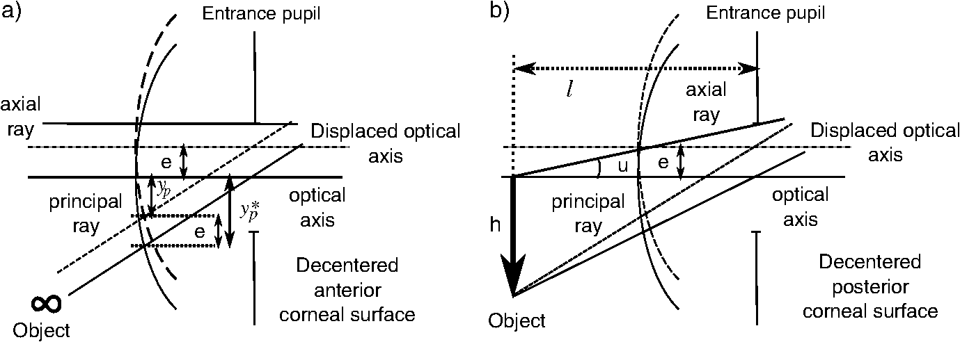 The lens is a decentered and tilted element. Therefore, the corresponding coefficients values for each surface (, ) are calculated using the following equations,67 from those when the lens is centered [Eq. (2)]: in which (, ) and (, ) are the slope and the heights, respectively, of the marginal, principal rays at the (, ) surface established by paraxial raytracing; (, ) is the slope and height, respectively, of a ray at each lens surface as if it was the optical axis determined by finite raytracing (Fig. 3); is the distance to the entrance pupil (iris) from the intersection of the tilted axis of the lens with that of the entrance pupil, and finally, is the distance from the object to the entrance pupil, (Fig. 4).2.2.3.Calculation of GRIN profile contributionSince the human crystalline lens is a GRIN one, we know there is a contribution to the Seidel coefficients when the light refracts from/to a GRIN media, as well as another contribution from the propagation of light inside the GRIN element to the posterior surface.66 The contribution to the refraction has a similar effect of working with an aspherical surface instead of a spherical one in the case of dealing with homogeneous media. Thus, we can calculate the first term of Eq. (1) as follows: in which are the GRIN profile contributions due to refraction at each crystalline lens surface, and are the GRIN profile contributions due to light propagating through the crystalline lens to the posterior surface.In Eqs. (7) and (8), is the thickness of the lens; and are the slope and the height, respectively, of the paraxial rays at a position inside the lens, where the sub-indices and refer to the marginal and principal rays, respectively; the parameters , are the first off-axis curvature of each hyperbolic lens surface,73 being its curvature and its asphericity; , , and are the GRIN profile coefficients as a function of position , assuming a rotationally symmetric GRIN medium, i.e. , as is the case for the lens as: in which, for the crystalline lens model,64 , is a constant value and .It is known that, up to the date of the software version used here (December, 2010), ZEMAX-EE did not correctly calculate the paraxial raytracing when the optical system dealt with GRIN media. Hence, the slope and the height of both marginal and principal rays were wrongly traced to the posterior surface of the lens. This means that these values cannot be used in Eq. (7) and (8). However, the use of the ABCD matrix of the lens70,71 permits them to be determined; therefore, the contribution of the GRIN profile to the refraction at the posterior lens surface, as well as the light transfer, can be calculated. Thus, the slope and the height of a ray at any point within a rotational symmetric GRIN medium can be determined by using the parabolic approximation as follows:70 where and are the slope and the height, respectively, of the ray after refraction at the first surface of the lens. Therefore, the slope and the height of a paraxial ray at the posterior human-lens surface can be calculated by using with , being the thickness of the GRIN medium, i.e. the lens thickness at a given age, and where withTherefore, the Seidel coefficients for the cornea are calculated adding Eqs. (3) and (4): Seidel coefficients for the lens are calculated by adding Eqs. (5), (7), and (8), this applied to each lens surface: and finally, Eq. (1) can be written by taking into account Eqs. (14) and (15) as:In Eqs. (14)–(16), stands for SI (spherical), SII (lateral coma) and SIII (H/V astigmatism) Seidel coefficients. 2.3.Zernike CoefficientsSeidel third-order aberrations help to express the wavefront aberration as a function of Cartesian coordinates in the pupil. Today, it is well-known that the widely accepted way to express the ocular aberrations is by means of the Zernike coefficients.74 Therefore, the Seidel coefficients have been expressed in terms of the approximate corresponding fourth-order Zernike coefficient counterparts using the following relationships:68,69 These expressions will be referred to here as fourth-order spherical, lateral (horizontal) coma, and H/V astigmatism, respectively. In addition, the fourth-order Zernike coefficients were scaled by using the relationships published elsewhere,75–77 when compared with those found in the experimental works with a smaller pupil. Table 2 lists the notation corresponding to the different Zernike coefficients when used for calculating different contributions from surfaces or from GRIN lens profile, for analyzing the results, and it also shows how they were calculated. Table 2Zernike coefficients corresponding to the contribution from the aspherical ocular surfaces, from the GRIN lens profile, and for the whole eye, determined from the Seidel coefficients counterpart.
3.Results3.1.Optical Surfaces and GRIN Separated Contributions to Ocular AberrationsFigure 5 shows the results corresponding to the fourth-order spherical aberration, lateral coma, and H/V astigmatism. These were calculated for both aspherical surfaces of the decentered cornea and for those of the misaligned lens, the contribution of the GRIN profile to refraction in both lens surfaces, contribution to light transfer through the GRIN, and finally, for the whole eye. Fig. 5Coefficient values corresponding to the fourth-order spherical aberration (top), horizontal coma (middle), and H/V astigmatism (bottom), calculated for the cornea, lens surfaces, contribution of the gradient-index (GRIN) profile to refraction in both lens surfaces, contribution to light transfer through the GRIN lens, and finally, the complete eye. 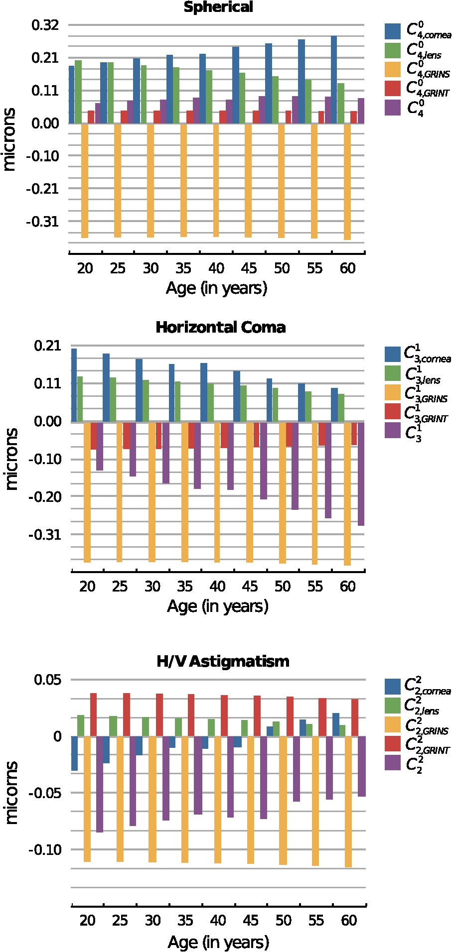 It can be seen that the coefficients values calculated for the cornea change with age and range from 0.19 to 0.28 microns for , from 0.20 to 0.10 microns for , and from to microns for . The variation found for the spherical aberration agrees with the data previously reported. The values calculated for the lateral coma and H/V astigmatism should be taken with caution, since the cornea assumed in the model is spherical, and the experimental coefficients determined for the cornea are measured using different reference points,78 and are often reported for the anterior corneal surface. In fact, the calculated values from its posterior surface for all the aberrations are small (about one order of magnitude). Nevertheless, the values reported in this work can be used to estimate the compensation made by the lens. From the same figure, several findings can be highlighted since the calculation of the coefficients values allowed the separation of the contribution from the aspherical surfaces (corneal and lenticular surfaces) as well as that from the GRIN profile. Thus, it can be seen that the main contribution to the ocular coefficients values corresponding to , , and is given by the GRIN profile to the refraction at the lens surfaces, i.e. , , . These values for the three ocular aberrations are negative and basically independent of the age, their magnitude being about microns, microns, and microns, for the spherical, horizontal coma, and H/V astigmatism, respectively. The contribution corresponding to the light transfer through the GRIN profile does not seem to depend on aging either. This contribution has the value of 0.042 microns for , −0.07 microns for , and 0.035 microns for . Finally, the values for , , and decrease with age. That is, the spherical aberration associated with the optical geometry of the lens surfaces decreases clearly with age from 0.20 to 0.13 microns, 0.13 to 0.08 microns for the horizontal coma, and 0.018 to 0.01 microns for the H/V astigmatism. 3.2.Compensation Between the Cornea and LensThe calculation of the different contributions to the aberration coefficients enables an investigation of the effect of the aberration compensation between the lens and the cornea. Particularly, Fig. 6 presents the corneal spherical aberration value, , and that of the lens, . It is clear that the corneal spherical aberration increases with the age. In addition, abberration of the lens also increases, but has the opposite sign and not enough increasing ratio as with the cornea. Therefore, the spherical aberration generated by the cornea will not be fully compensated for. However, the total ocular fourth-order aberration does not augment with aging (from 0.066 to 0.089 microns, with a mean value of 0.077 microns). This agrees with experimental studies such as those of Atchison and Markwell29 (mean value of 0.061 microns, at a 5-mm pupil, 0.082 microns scaled in this study), Plainins and Pallikaris (ranking form to 0.26 microns at a 6-mm pupil), Cheng et al.79 (0.132 microns at a 6-mm pupil), He et al.21 (0.06 microns at a 6-mm pupil), or Radhakrishnan and Charman28 (mean value of 0.034 microns at a 4.5-mm pupil, 0.053 microns scaled in this study), and it is about one-half of that in other studies.17,18,20,22,23,25,26,54,56 Fig. 6Corneal aberrations compensation by the lens: spherical aberration (top), horizontal coma, and horizontal/verticle (H/V) astigmatism (bottom).  The lens does not compensate for the horizontal corneal coma, since its value, , increases in magnitude with an opposite sign and a higher ratio compared to , which decreases (Fig. 6). Those values range from to microns while for the corneal horizontal coma declines with age from 0.2 to 0.09 microns. The trend of these values agrees with that reported in different studies, but the magnitude of the values is greater than some of them, even when the studies consider the third- and fifth-order root-mean-square (RMS) values.24,28,29,54,80. Other studies agree with our results when considering mean values.56,81 Finally, Fig. 6 also shows that the H/V astigmatism of the lens, , is almost constant (a value around microns) with aging. Thus, the lens astigmatism does not compensate for that of the cornea, . However, the magnitude of this aberration value compared to the others is very low. 3.3.Analysis of the GRIN Profile RoleThe effect of the GRIN profile was also analyzed by representing its relative contribution (both refraction and light transfer) compared to the joint optical ocular surfaces of the cornea and the lens (Fig. 7). Regarding the spherical aberration, the GRIN profile contribution, , is almost constant and cannot compensate for the contribution corresponding to the optical surfaces, , which slightly increases with age due to the change in the optical geometry of the corneal and the lenticular surfaces.2,3 However, the GRIN profile over-compensates for the effect of the horizontal coma, caused by the optical surfaces, and thus, the overall ocular coma. That is, the GRIN contribution, , has a different sign and compensates for the horizontal coma that comes from the surfaces, , leading to an overall increase with age ( to microns). This value is slightly higher compared to those reported in experimental studies,28,29,49,82 although, the variation agrees with others.57,80,83 Fig. 7Role of the gradient-index (GRIN) profile in the compensation for the ocular aberrations induced by ocular surfaces: spherical aberration (top), horizontal coma, and horizontal/vertical (H/V) astigmatism (bottom).  In the case of the H/V astigmatism, both contributions, that of the GRIN profile, , and that of the optical surfaces, , add up to 30 years, and then have opposite signs (Fig. 7). The value corresponding to the optical surfaces increases with age, while that corresponding to the GRIN profile is almost constant, and thus the astigmatism would seem to decrease through life. However, it can be seen that the magnitude of the value is small compared to those of the spherical and horizontal coma, supporting the claim that the astigmatism is not so important in central vision, at least for emmetropic eyes. 4.DiscussionSeveral experimental studies have demonstrated the robustness of the design of the human eye to compensate for ocular aberrations between the different elements. Thus, corneal aberrations, particularly spherical aberration and horizontal coma, are partially compensated for by the decentered and tilted lens, as well as decentration of the pupil. Moreover, the change of that compensation between cornea and internal optics has been postulated to be partially dependent on the variation in the lens geometry, in the alignment with respect to the cornea, as well as in the GRIN profile throughout life.31,47,54,57,58 A number of studies have contended that the fourth-order spherical aberration does not vary with age22,29 while others hold that it does.28,31,80 This study also demonstrates that the lens cannot fully compensate for the spherical aberration of the cornea. However, it makes the total value retain its value with age. Notably, the change of the GRIN profile with aging is responsible for this effect, since the optical surfaces of the lens by themselves could not do so. The modelling shows that the corneal and the lens surfaces add to the spherical aberration with the age. However, since the lens-surface contribution decreases, this cannot account for the variation of the ocular spherical aberration.58 In addition, the fourth-order spherical aberration is not affected by the decentration and tilt between the cornea and lens with respect to the iris, as shown in the Eqs. (3)–(5). This could support the hypothesis that the role of the GRIN lens profile is that of a passive physiological mechanism, having a genetic origin, as has been postulated by other authors.54 Moreover, the most relevant term in the compensation is that of the GRIN profile contribution to the refraction, in contrast to the transfer term, which has a small one. This could indicate the minor effect on the spherical aberration of the refractive-index axial variation within the lens. However, when Eqs. (7) and (8) are taken into account, this axial variation is found to be responsible not only for the aberration contribution to the wavefront through the lens, but also for the refraction. Thus, a coupling effect of the geometry of the lens surfaces and the GRIN profile, given by Eq. (7), appears to be determinant in the compensation of the spherical ocular aberration.62,63 Therefore, since the asphericities of the surfaces drive the contribution, reliable measurements are needed, as has been pointed out previously.58 Regarding the corneal horizontal coma, there are studies reporting no significant variation with age.29,31 The modelling reported in the present work indicates that the corneal horizontal coma does indeed diminish slightly throughout life, with a mean value of 0.17 microns. Nevertheless, it should be taken into account how these values are calculated compared to those from experimental studies. In the latter, the keratometric axis sets the anterior corneal pole in a different position from that of the corneal model. The rotation for correcting this reference point adds changes in the measured values for the corneal horizontal coma, which are not considered in the model eye. Internal optics does help to compensate slightly for the corneal coma, and thus, an increase arises with age. Again, the GRIN profile contribution to the horizontal coma is almost constant and it has an opposite sign compared to that from the optical surfaces. Horizontal coma is affected by the kappa angle, and this angle affects the coupling with the spherical aberration, as reflected by Eq. (5). Thus, it is conceivable that a fine tuning in the compensation between the cornea and lens may occur in individual subjects by varying the angle kappa, as several studies have shown.31,49 Therefore, an active mechanism could take place in order to balance the spherical aberration with the ocular horizontal coma. Finally, regarding the H/V astigmatism, although the trend is consistent with that reported in the literature, it should be discussed from a more conservative viewpoint. Moreover, this ocular aberration is of less relevance, since spherical and coma are the most important ocular aberrations limiting image quality in humans.47 In this regard, it should even be noted that our model has a rotationally symmetric cornea, which does not take into account the corneal astigmatism. This may overestimate the value of the compensation of astigmatism by the lens. However, if only the contribution of the latter is considered, again the relevant term is the contribution of the GRIN profile to the refraction. In addition, the coupling of spherical aberration and coma through the offset and rotation must be taken into account, as shown by Eq. (5). The notable weight that the GRIN profile has on the compensation of the aberrations between the cornea and the lens reveals that its role cannot be neglected in that compensation. Thus, optical surfaces themselves cannot explain the failure in the balance for the ocular aberrations, particularly for the horizontal coma. A recent modelling has been made along this line, considering both the cornea and lens as spherical thin lenses,31,49,58 and it has been concluded that better knowledge of the changes in the lens-surface asphericities and GRIN profile could support a better understanding of that decoupling. Although those studies could have considered the aspherical thin lenses,84 for which the horizontal coma is not linear with the shape factor because of coupling with the spherical term [Eq. (5)], this study agrees that the role played by the GRIN profile appears to be fundamental. In summary, current eye models are based on experimental data regarding the geometrical surface parameters as well as the GRIN profile. Then, optimisation methods are performed based on the aberration data gained experimentally as well. Several degrees of freedom can be set in the eye models to fit the experimental data. However, more reliable measurements regarding the misalignments between the lens and the cornea, the lens-surface geometry and, particularly, the GRIN profile, are needed to get an accurate eye model. The aging GRIN profile equation proposed recently for the human lens64 seems robust enough to formulate a better aging-eye model,65 including misalignments between ocular elements as well as non-rationally symmetric surfaces. Moreover, the modelling of this study has demonstrated the coupling of the asphericities of the lens surfaces with the GRIN profile, providing the main factor in balancing the ocular aberrations. 5.ConclusionThis paper presents a modelling study, based on an aging-eye model, of the time course of the third-order spherical aberration, horizontal coma, and H/V astigmatism, by including misalignments between ocular elements and a GRIN lens. The role of a GRIN lens profile is revealed from its main contribution to all the ocular aberrations studied. Moreover, the GRIN profile should be taken into account because the contribution of the lens optical surfaces alone fails to explain the decoupling of the aberrations between the cornea and the lens. ReferencesN. Brown,
“The change in lens curvature with age,”
Exp. Eye Res., 19 175
–183
(1974). http://dx.doi.org/10.1016/0014-4835(74)90034-7 EXERA6 0014-4835 Google Scholar
M. DubbelmanG. L. Van der HeijdeH. A. Weeber,
“Change in shape of the aging human crystalline lens with accommodation,”
Vis. Res., 45 117
–132
(2005). http://dx.doi.org/10.1016/j.visres.2004.07.032 VISRAM 0042-6989 Google Scholar
M. DubbelmanV. A. D. P. SicamG. L. Van der Heijde,
“The shape of the anterior and posterior surface of the aging human cornea,”
Vis. Res., 46 993
–1001
(2006). http://dx.doi.org/10.1016/j.visres.2005.09.021 VISRAM 0042-6989 Google Scholar
M. DubbelmanV. A. D. P. SicamR. G. L. van der Heijde,
“The contribution of the posterior surface to the coma aberration of the human cornea,”
J. Vis., 7
(7), 1
–8
(2007). http://dx.doi.org/10.1167/7.7.10 1534-7362 Google Scholar
D. A. Atchisonet al.,
“Age-related changes in optical and biometric characteristics of emmetropic eyes,”
J. Vis., 8
(4), 1
–20
(2008). http://dx.doi.org/10.1167/8.4.29 1534-7362 Google Scholar
B. Pierscionek,
“Gradient index optics in the eye,”
Handbook of Optics, McGraw-Hill, New York
(2009). Google Scholar
B. Pierscionek,
“Species variations in the refractive index of the eye lens and patterns of change with ageing,”
Focus on eye research, 117
–132 Nova Science, New York
(2005). Google Scholar
B. K. Pierscionek,
“Refractive index contours in the human lens,”
Exp. Eye Res., 64 887
–893
(1997). http://dx.doi.org/10.1006/exer.1996.0252 EXERA6 0014-4835 Google Scholar
B. K. Pierscionek,
“Refractive index of the human lens surface measured with an optic fibre sensor,”
Ophthalmic Res., 26 32
–35
(1994). http://dx.doi.org/10.1159/000267371 OPRSAQ 0030-3747 Google Scholar
B. K. PierscionekR. C. Augusteyn,
“Structure/function relationship between optics and biochemistry of the lens,”
Lens Eye Toxic Res., 8 229
–243
(1991). LETRET 1042-6922 Google Scholar
B. K. PierscionekD. Y. Chan,
“Refractive index gradient of human lenses,”
Optom. Vis. Sci., 66 822
–829
(1989). http://dx.doi.org/10.1097/00006324-198912000-00004 OVSCET 1040-5488 Google Scholar
B. A. MoffatD. A. AtchisonJ. M. Pope,
“Age-related changes in refractive index distribution and power of the human lens as measured by magnetic resonance micro-imaging in vitro,”
Vis. Res., 42 1683
–1693
(2002). http://dx.doi.org/10.1016/S0042-6989(02)00078-0 VISRAM 0042-6989 Google Scholar
J. M. PopeD. A. AtchisonB. A. Moffat,
“Age-related changes of the refractive index of the crystalline lens,”
Vis. Res., 42 2809
(2002). http://dx.doi.org/10.1016/S0042-6989(02)00407-8 VISRAM 0042-6989 Google Scholar
M. Dubbelmanet al.,
“Changes in the internal structure of the human crystalline lens with age and accommodation,”
Vis. Res., 43 2363
–2375
(2003). http://dx.doi.org/10.1016/S0042-6989(03)00428-0 VISRAM 0042-6989 Google Scholar
C. E. JonesJ. M. Pope,
“Measuring optical properties of an eye lens using magnetic resonance imaging,”
Magnetic Resonance Imaging, 22 211
–220
(2004). http://dx.doi.org/10.1016/j.mri.2003.07.005 MRIMDQ 0730-725X Google Scholar
C. E. Joneset al.,
“Refractive index distribution and optical properties of the isolated human lens measured using magnetic resonance imaging (MRI),”
Vis. Res., 45 2352
–2366
(2005). http://dx.doi.org/10.1016/j.visres.2005.03.008 VISRAM 0042-6989 Google Scholar
J. L. Alioet al.,
“Crystalline lens optical dysfunction through aging,”
Ophthalmology, 112 2022
–2029
(2005). http://dx.doi.org/10.1016/j.ophtha.2005.04.034 OPANEW 0743-751X Google Scholar
R. I. CalverM. J. CoxD. B. Elliott,
“Effect of aging on the monochromatic aberrations of the human eye,”
J. Opt. Soc. Am. A, 16 2069
–2078
(1999). http://dx.doi.org/10.1364/JOSAA.16.002069 JOAOD6 0740-3232 Google Scholar
S. D. KlyceT. OshikaR. A. ApplegateH. C. Howland,
“Changes in corneal wavefront aberrations with aging,”
Invest. Ophthalmol. Vis. Sci., 40 1351
–1355
(1999). IOVSDA 0146-0404 Google Scholar
J. Porteret al.,
“Monochromatic aberrations of the human eye in a large population,”
J. Opt. Soc. Am. A Opt. Image Sci. Vis., 18 1793
–1803
(2001). http://dx.doi.org/10.1364/JOSAA.18.001793 JOAOD6 0740-3232 Google Scholar
J. C. Heet al.,
“Wavefront aberrations in eyes of emmetropic and moderately myopic school children and young adults,”
Vis. Res., 42 1063
–1070
(2002). http://dx.doi.org/10.1016/S0042-6989(02)00035-4 VISRAM 0042-6989 Google Scholar
P. Artalet al.,
“Contribution of the cornea and internal surfaces to the change of ocular aberrations with age,”
J. Opt. Soc. Am. A, 19 137
–143
(2002). http://dx.doi.org/10.1364/JOSAA.19.000137 JOAOD6 0740-3232 Google Scholar
L. N. Thiboset al.,
“Statistical variation of aberration structure and image quality in a normal population of healthy eyes,”
J. Opt. Soc. Am. A Opt. Image Sci. Vis., 19 2329
–2348
(2002). http://dx.doi.org/10.1364/JOSAA.19.002329 JOAOD6 0740-3232 Google Scholar
I. Brunetteet al.,
“Monochromatic aberrations as a function of age, from childhood to advanced age,”
Invest. Ophthalmol. Vis. Sci., 44 5438
–5446
(2003). http://dx.doi.org/10.1167/iovs.02-1042 IOVSDA 0146-0404 Google Scholar
L. WangD. D. Koch,
“Age-related changes in corneal and ocular higher-order aberrations,”
Am. J. Ophthalmol., 138 897
(2004). http://dx.doi.org/10.1016/j.ajo.2004.07.024 AJOPAA 0002-9394 Google Scholar
S. Amanoet al.,
“Age-related changes in corneal and ocular higher-order wavefront aberrations,”
Am. J. Ophthalmol., 137 988
–992
(2004). http://dx.doi.org/10.1016/j.ajo.2004.01.005 AJOPAA 0002-9394 Google Scholar
L. Wanget al.,
“Higher-order aberrations from the internal optics of the eye,”
J. Cataract Refract. Surg., 31 1512
–1519
(2005). http://dx.doi.org/10.1016/j.jcrs.2004.01.048 JCSUEV 0886-3350 Google Scholar
H. RadhakrishnanW. N. Charman,
“Age-Related changes in ocular aberrations with accommodation,”
J. Vis., 7
(7), 1
–21
(2007). http://dx.doi.org/10.1167/7.7.11 1534-7362 Google Scholar
D. A. AtchisonE. L. Markwell,
“Aberrations of emmetropic subjects at different ages,”
Vis. Res., 48 2224
–2231
(2008). http://dx.doi.org/10.1016/j.visres.2008.06.023 VISRAM 0042-6989 Google Scholar
S. L. Elliottet al.,
“Role of high-order aberrations in senescent changes in spatial vision,”
J. Vis., 9
(2), 1
–16
(2009). http://dx.doi.org/10.1167/9.2.24 1534-7362 Google Scholar
E. BerrioJ. TaberneroP. Artal,
“Optical aberrations and alignment of the eye with age,”
J. Vis., 10
(14), 1
–17
(2010). http://dx.doi.org/10.1167/10.14.34 1534-7362 Google Scholar
L. WangD. D. Koch,
“Effect of decentration of wavefront-corrected intraocular lenses on the higher-order aberrations of the eye,”
Arch. Ophthalmol., 123 1226
–1230
(2005). http://dx.doi.org/10.1001/archopht.123.9.1226 AROPAW 0003-9950 Google Scholar
J. TaberneroP. PiersP. Artal,
“Intraocular lens to correct corneal coma,”
Opt. Lett., 32 406
–408
(2007). http://dx.doi.org/10.1364/OL.32.000406 OPLEDP 0146-9592 Google Scholar
J. Taberneroet al.,
“Predicting the optical performance of eyes implanted with IOLs to correct spherical aberration,”
Invest. Ophthalmol. Vis. Sci., 47 4651
–4658
(2006). http://dx.doi.org/10.1167/iovs.06-0444 IOVSDA 0146-0404 Google Scholar
J. A. Díazet al.,
“Optimum corneal asphericity of myopic eyes for refractive surgery,”
J. Modern Optics, 50 1903
–1915
(2003). http://dx.doi.org/10.1080/09500340308235245 JMOPEW 0950-0340 Google Scholar
J. A. Díazet al.,
“Permissible lateral misalignments in corneal ablation for myopic eyes,”
J. Optics a-Pure Appl. Opt., 7 364
–367
(2005). http://dx.doi.org/10.1088/1464-4258/7/8/002 JOAOF8 1464-4258 Google Scholar
E. Gambraet al.,
“Dynamic accommodation with simulated targets blurred with high order aberrations,”
Vis. Res., 50 1922
–1927
(2010). http://dx.doi.org/10.1016/j.visres.2010.06.015 VISRAM 0042-6989 Google Scholar
L. GonzálezJ. L. Hernández-MatamorosR. Navarro,
“Multizone model for postsurgical corneas: analysis of standard and custom LASIK outcomes,”
J. Biomed. Opt., 13
(4), 044035
(2008). http://dx.doi.org/10.1117/1.2960621 JBOPFO 1083-3668 Google Scholar
M. A. KhalifaW. A. AllamA. M. Khalifa,
“Improving near vision in presbyopic eyes by selective treatment of high-order aberrations,”
Clin. Ophthalmol., 5 1525
–1530
(2011). http://dx.doi.org/10.2147/OPTH COLPCK 1177-5483 Google Scholar
J. Y. Shinet al.,
“Comparison of higher order aberrations after implantable collamer lens implantation and wavefront-guided LASEK in high myopia,”
J. Refract. Surg., 28
(2), 106
–111
(2012). JRSUEY 0883-0444 Google Scholar
M. C. Campbell,
“Measurement of refractive index in an intact crystalline lens,”
Vis. Res., 24 409
–415
(1984). http://dx.doi.org/10.1016/0042-6989(84)90039-7 VISRAM 0042-6989 Google Scholar
M. C. CampbellA. Hughes,
“An analytic, gradient index schematic lens and eye for the rat which predicts aberrations for finite pupils,”
Vis. Res., 21 1129
–1148
(1981). http://dx.doi.org/10.1016/0042-6989(81)90016-X VISRAM 0042-6989 Google Scholar
R. H. KrogerM. C. CampbellR. D. Fernald,
“The development of the crystalline lens is sensitive to visual input in the African cichlid fish, Haplochromis burtoni,”
Vis. Res., 41 549
–559
(2001). http://dx.doi.org/10.1016/S0042-6989(00)00283-2 VISRAM 0042-6989 Google Scholar
R. H. Krogeret al.,
“Refractive index distribution and spherical aberration in the crystalline lens of the African cichlid fish Haplochromis burtoni,”
Vis. Res., 34 1815
–1822
(1994). http://dx.doi.org/10.1016/0042-6989(94)90306-9 VISRAM 0042-6989 Google Scholar
J. G. SivakR. O. Kreuzer,
“Spherical aberration of the crystalline lens,”
Vis. Res., 23 59
–70
(1983). http://dx.doi.org/10.1016/0042-6989(83)90042-1 VISRAM 0042-6989 Google Scholar
P. ArtalA. Guirao,
“Contributions of the cornea and the lens to the aberrations of the human eye,”
Opt. Lett., 23 1713
–1715
(1998). http://dx.doi.org/10.1364/OL.23.001713 OPLEDP 0146-9592 Google Scholar
P. ArtalA. BenitoJ. Tabernero,
“The human eye is an example of robust optical design,”
J. Vis., 6
(1), 1
–7
(2006). http://dx.doi.org/10.1167/6.1.1 1534-7362 Google Scholar
J. S. McLellanet al.,
“Effects of interactions among wave aberrations on optical image quality,”
Vis. Res., 46 3009
–3016
(2006). http://dx.doi.org/10.1016/j.visres.2006.03.005 VISRAM 0042-6989 Google Scholar
J. Taberneroet al.,
“Mechanism of compensation of aberrations in the human eye,”
J. Opt. Soc. Am. A Opt. Image Sci. Vis., 24 3274
–3283
(2007). http://dx.doi.org/10.1364/JOSAA.24.003274 JOAOD6 0740-3232 Google Scholar
R. Navarro,
“The optical design of the human eye: a critical review,”
J. Optom., 2 3
–18
(2009). Google Scholar
M. MillodotJ. Sivak,
“Contribution of the cornea and lens to the spherical aberration of the eye,”
Vis. Res., 19 685
–687
(1979). http://dx.doi.org/10.1016/0042-6989(79)90244-X VISRAM 0042-6989 Google Scholar
J. G. Sivak,
“The contribution of the crystalline lens to chromatic and spherical aberrations of the eye,”
Can. J. Optom., 44 89
–91
(1982). Google Scholar
S. G. el-HageF. Berny,
“Contribution of the crystalline lens to the spherical aberration of the eye,”
J. Opt. Soc. Am., 63 205
–211
(1973). http://dx.doi.org/10.1364/JOSA.63.000205 JOSAAH 0030-3941 Google Scholar
J. E. KellyT. MihashiH. C. Howland,
“Compensation of corneal horizontal/vertical astigmatism, lateral coma, and spherical aberration by internal optics of the eye,”
J. Vis., 4
(4), 262
–271
(2004). http://dx.doi.org/10.1167/4.4.2 1534-7362 Google Scholar
F. Luet al.,
“On the compensation of horizontal coma aberrations in young human eyes,”
Ophthalm. Physiol. Opt., 28 277
–282
(2008). http://dx.doi.org/10.1111/j.1475-1313.2008.00565.x OPOPD5 0275-5408 Google Scholar
T. O. SalmonC. van de Pol,
“Normal-eye Zernike coefficients and root-mean-square wavefront errors,”
J. Cataract Refract. Surg., 32 2064
–2074
(2006). http://dx.doi.org/10.1016/j.jcrs.2006.07.022 JCSUEV 0886-3350 Google Scholar
S. Marcoset al.,
“Balance of corneal horizontal coma by internal optics in eyes with intraocular artificial lenses: evidence of a passive mechanism,”
Vis. Res., 48 70
–79
(2008). http://dx.doi.org/10.1016/j.visres.2007.10.016 VISRAM 0042-6989 Google Scholar
J. TaberneroE. BerrioP. Artal,
“Modeling the mechanism of compensation of aberrations in the human eye for accommodation and aging,”
J. Opt. Soc. Am. A, 28 1889
–1895
(2011). http://dx.doi.org/10.1364/JOSAA.28.001889 JOAOD6 0740-3232 Google Scholar
S. G. E. H. Y. Le Grand, Physiological Optics, Springer-Verlag, Berlin
(1980). Google Scholar
J. EspinosaD. MasH. T. Kasprzak,
“Corneal primary aberrations compensation by oblique light incidence,”
J. Biomed. Opt., 14
(4), 044003
(2009). http://dx.doi.org/10.1117/1.3158996 JBOPFO 1083-3668 Google Scholar
A. V. GoncharovC. Dainty,
“Wide-field schematic eye models with gradient-index lens,”
J. Opt. Soc. Am. A Opt. Image Sci. Vis., 24 2157
–2174
(2007). http://dx.doi.org/10.1364/JOSAA.24.002157 JOAOD6 0740-3232 Google Scholar
R. NavarroF. PalosL. González,
“Adaptive model of the gradient index of the human lens. I. Formulation and model of aging ex vivo lenses,”
J. Opt. Soc. Am. A, 24 2175
–2185
(2007). http://dx.doi.org/10.1364/JOSAA.24.002175 JOAOD6 0740-3232 Google Scholar
R. NavarroF. PalosL. M. González,
“Adaptive model of the gradient index of the human lens. II. Optics of the accommodating aging lens,”
J. Opt. Soc. Am. A, 24 2911
–2920
(2007). http://dx.doi.org/10.1364/JOSAA.24.002911 JOAOD6 0740-3232 Google Scholar
J. A. DíazC. PizarroJ. Arasa,
“Single dispersive gradient-index profile for the aging human lens,”
J. Opt. Soc. Am. A Opt. Image Sci. Vis., 25 250
–261
(2008). http://dx.doi.org/10.1364/JOSAA.25.000250 JOAOD6 0740-3232 Google Scholar
J. A. Díazet al.,
“Analysis of the robustness of the lens GRIN profile in a schematic model eye,”
J. Modern Opt., 58 1764
–1769
(2011). http://dx.doi.org/10.1080/09500340.2011.572193 JMOPEW 0950-0340 Google Scholar
P. J. Sands,
“Third-order aberrations of inhomogeneous lenses,”
J. Opt. Soc. Am., 60 1436
–1443
(1970). http://dx.doi.org/10.1364/JOSA.60.001436 JOSAAH 0030-3941 Google Scholar
P. L. Ruben,
“Aberrations arising from decentrations and tilts,”
J. Opt. Soc. Am., 54 45
–46
(1964). http://dx.doi.org/10.1364/JOSA.54.000045 JOSAAH 0030-3941 Google Scholar
G. Conforti,
“Zernike aberration coefficients from Seidel and higher-order power-series coefficients,”
Opt. Lett., 8 407
–408
(1983). http://dx.doi.org/10.1364/OL.8.000407 OPLEDP 0146-9592 Google Scholar
G.-M. Dai, Wavefront Optics for Vision Correction, SPIE Press, Bellingham WA
(2007). Google Scholar
J. A. Díaz,
“ABCD matrix of the human lens gradient-index profile: applicability of the calculation methods,”
Appl. Opt., 47 195
–205
(2008). http://dx.doi.org/10.1364/AO.47.000195 APOPAI 0003-6935 Google Scholar
F. Sorrocheet al.,
“ABCD matrix for calculating third-order aberrations of gradient index optical elements,”
Proc. SPIE, 7652 76522X
(2010). http://dx.doi.org/10.1117/12.868444 Google Scholar
ZEMAX-EE Optical Design Software Manual, Redmon, WA
(2010). Google Scholar
H. A. Buchdahl, Optical aberration coefficients, 107
–108 Dover Publications, New York
(1968). Google Scholar
L. N. Thiboset al.,
“Standards for reporting the optical aberrations of eyes,”
J. Refract. Surg., 18 S652
–S660
(2002). JRSUEY 0883-0444 Google Scholar
J. Schwiegerling,
“Scaling Zernike expansion coefficients to different pupil sizes,”
J. Opt. Soc. Am. A, 19 1937
–1945
(2002). http://dx.doi.org/10.1364/JOSAA.19.001937 JOAOD6 0740-3232 Google Scholar
G.-M. Dai,
“Scaling Zernike expansion coefficients to smaller pupil sizes: a simpler formula,”
J. Opt. Soc. Am. A, 23 539
–543
(2006). http://dx.doi.org/10.1364/JOSAA.23.000539 JOAOD6 0740-3232 Google Scholar
J. A. Díazet al.,
“Zernike coefficients for concentric, circular scaled pupils: an equivalent expression,”
J. Modern Opt., 56 131
–137
(2009). http://dx.doi.org/10.1080/09500340802531224 JMOPEW 0950-0340 Google Scholar
T. O. SalmonL. N. Thibos,
“Videokeratoscope-line-of-sight misalignment and its effect on measurements of corneal and internal ocular aberrations,”
J. Opt. Soc. Am. A Opt. Image Sci. Vis., 19 657
–669
(2002). http://dx.doi.org/10.1364/JOSAA.19.000657 JOAOD6 0740-3232 Google Scholar
X. Chenget al.,
“Relationship between refractive error and monochromatic aberrations of the eye,”
Optom. Vis. Sci., 80 43
–49
(2003). http://dx.doi.org/10.1097/00006324-200301000-00007 OVSCET 1040-5488 Google Scholar
R. A. Applegateet al.,
“Three-dimensional relationship between high-order root-mean-square wavefront error, pupil diameter, and aging,”
J. Opt. Soc. Am. A Opt. Image Sci. Vis., 24 578
–587
(2007). http://dx.doi.org/10.1364/JOSAA.24.000578 JOAOD6 0740-3232 Google Scholar
L. Wanget al.,
“Optical aberrations of the human anterior cornea,”
J. Cataract Refract. Surg., 29 1514
–1521
(2003). http://dx.doi.org/10.1016/S0886-3350(03)00467-X JCSUEV 0886-3350 Google Scholar
S. PlainisE. PlevridiI. G. Pallikaris,
“Comparison of the ocular wavefront aberration between pharmacologically-induced and stimulus-driven accommodation,”
Ophthalm. Physiol. Opt., 29 272
–280
(2009). http://dx.doi.org/10.1111/opo.2009.29.issue-3 OPOPD5 0275-5408 Google Scholar
J. C. Heet al.,
“Wave-front aberrations in the anterior corneal surface and the whole eye,”
J. Opt. Soc. Am. A Opt. Image Sci. Vis., 20 1155
–1163
(2003). http://dx.doi.org/10.1364/JOSAA.20.001155 JOAOD6 0740-3232 Google Scholar
J. A. Díaz,
“Primary aberrations of a thin lens with standard aspheres,”
Proc. SPIE, 5249 599
–607
(2004). http://dx.doi.org/10.1117/12.512370 Google Scholar
|
||||||||||||||||||||||||||||||||||||||||||||||||||||||||||||||||||


