
|
|
1.IntroductionChanges to ultraviolet-visible transmission spectra have been cited in claims that the optical qualities of intraocular lenses (IOLs) are affected by surface light scattering,1,2 which is caused by subsurface nanoglistenings.3 The ability to draw accurate conclusions about this topic depends on the appropriateness of the instrumentation used to make the measurements. Ultraviolet-visible spectra of IOLs and explanted crystalline lenses are commonly measured by using double-beam spectrophotometers4,5 or spectrophotometers equipped with integrating spheres.6–9 The use of integrating spheres for ophthalmic optics is advocated by researchers in both industry and academia. Industrial proponents of using an integrating sphere to measure the transmittance of IOLs include the International Organization for Standardization (ISO) and the American National Standards Institute (ANSI). ISO and ANSI standards for transmittance of IOLs do not explicitly require an integrating sphere,10,11 but both refer to the ISO standard for contact lenses, which does specify the use of an integrating sphere.12 Clinical and academic researchers who have measured the transmittance of ex vivo crystalline lenses have noted that if the integrating sphere were omitted, then the chromatic and spectral aberrations of the lens could significantly affect the lens transmission characteristics, depending on the exact positioning of the lens in the spectrophotometer.7 Research that measured the transmission spectra of contact lenses with and without integrating spheres established that integrating spheres are necessary to ensure the accuracy of the data.13 However, no such research (to our knowledge) has been published concerning the transmission spectra of explanted IOLs with surface light scattering, measured with or without an integrating sphere. The purpose of this study was to investigate the differences between integrating-sphere and double-beam methodologies for measuring the ultraviolet/visible transmission of IOLs when varying a number of parameters, including IOL power range, ambient temperature versus physiologically relevant 35°C, and presence or absence of surface light scattering. 2.Methods2.1.Spectrophotometry EquipmentA PerkinElmer Lambda is spectrophotometer (PerkinElmer, Waltham, MA) was operated in a single-beam configuration with a Lab Sphere RSA-PE-20 integrating sphere with a 50-mm diameter (PerkinElmer) or was operated in a double-beam configuration with two photodiode detectors (one for the sample beam and one for the reference beam). The monochromator was a holographic concave grating with in the center. The light sources were a deuterium lamp for the ultraviolet region and a tungsten halogen lamp for the visible region. 2.2.Integrating-Sphere MeasurementsWith the integrating sphere, transmission spectra were acquired in accordance with the relevant ISO standard,10 which refers to an earlier standard.12 Figure 1 shows a schematic of measuring transmittance of the sample IOL with the integrating-sphere configuration. The IOL under analysis was placed into a plastic custom insert that had a 5-mm-diameter aperture and was designed to hold the haptics of the IOL. The custom insert was mounted into a standard rectangular quartz cuvette with a 10-mm path. The quartz cuvette then was filled with balanced salt solution (BSS) (Alcon Laboratories; Fort Worth, TX) and placed directly in front of the opening of the integrating sphere. The quartz cuvette with the custom insert was aligned so that the light passed through the middle of the aperture into the integrating sphere. In integrating-sphere mode, the beam size where sample was located was 2.5 mm in diameter. Fig. 1Measuring transmittance of an intraocular lens (IOL) with an integrating sphere. The gray beam (thick beam) represents on-axis transmitted light. The green and violet beams (thin beams) represent light that has been scattered, refracted off-axis, or otherwise aberrated at the sample. The custom IOL holder is not shown.  Spectra were collected at ambient temperature unless otherwise noted. First, a background correction was performed with the empty insert holder immersed in BSS in a quartz cuvette. Background transmittance spectra were checked to ensure that 100% transmittance was achieved, and background was checked in every other sample measurement to ensure that the background did not shift ( or transmittance) during measurements. The insert holder was loaded with the IOL into the quartz cuvette in BSS. The transmission spectrum was acquired over the wavelength range of 300 to 850 nm at a scanning rate of and with a spectral slit width of 2 nm. Data were collected in 1-nm increments. During measurements, the solution-filled cuvette was inspected for trapped air bubbles in the light path; any bubbles were carefully eliminated. At least two measurements were recorded for each IOL and were averaged. If more measurements were recorded, all were averaged (up to four scans per IOL). 2.3.Double-Beam MeasurementsDouble-beam spectra were collected by using the same custom IOL holder in the cuvette; this lens-containing cuvette was placed in the sample beam path. A reference quartz cuvette, containing BSS and an empty IOL holder, was placed in the reference cuvette compartment. The sample cuvette and the reference cuvette were aligned so that the light passed through the centers of the apertures into the detectors (photodiodes). In double-beam mode, the beam size where the sample was located was 1 mm in diameter. Figure 2 shows the configuration of measuring the transmittance of the IOL in double-beam mode. The incoming beam from a light source is split into two paths by a beam splitter. The material being tested (in this case, an IOL) is positioned in one of the light paths. Transmitted light intensity is measured and compared with the intensity at the reference path to determine the transmittance. With most spectrophotometers, the beam usually is collimated or is weakly converging or diverging over the beam paths, and then is focused by a spectrophotometer lens onto a detector. Fig. 2Measuring transmittance of an intraocular lens in double-beam mode. The gray beam (thick beam) represents on-axis transmitted light. The green and violet beams (thin beams) represent light that has been scattered, refracted off-axis, or otherwise aberrated at the sample. The IOL holder is not shown.  2.4.Measuring Effects of Lens Power on TransmittanceSpectra were captured in double-beam mode and integrating-sphere mode. Transmittance was measured using finished-goods inventory AcrySof IOLs of model MA60BM (Alcon) with powers of 16.0, 20.0, 24.5, 28.5, and 30.0 D. Lenses were hydrated a minimum of 24 h in BSS before analysis. 2.5.Calculating Power/Wavelength DependencePublished values of 1.55 units at 587.6 nm for the refractive index of AcrySof IOL material and 37 units for the Abbe number of AcrySof IOL material14 were used to determine that the refractive indices of AcrySof material were approximately 1.566 units at 450 nm and 1.538 units at 850 nm. Interactions between refractive indices at these wavelengths (450 and 850 nm) and resultant lens power were calculated by using the “lens maker’s equation” for thin lenses,15 as follows: where is the refractive index and and are the radii of curvature of the lens. Calculations assumed the IOLs were in water (). Power/wavelength variations were calculated for IOLs having labeled powers of 6.0, 16.0, and 30.0 D.2.6.Modeling Beam SizeBeam size variation (as a result of an IOL positioned in the sample holder) was calculated in Zemax software (Radiant Zemax, Bellevue, WA), using the first-order approximation. These calculations did not account for spherical aberration, misalignment, or tilting of the IOL. Divergence of the beam was calculated in both the vertical and horizontal axes. The collimated beam size was set to 5 mm at the sample, because of the aperture of the custom IOL holder. In the double-beam configuration of the spectrophotometer, the instrument contained a lens with a focal length of 22.7 mm that was used to focus the beam onto a photodetector (see Fig. 1). The photosensitive area on the photodiode detector was 3.7 by 3.7 mm. These parameters were included in the modeling calculations. 2.7.Measuring Effects of Surface Light Scattering on TransmittanceThree IOLs that had been explanted in clinics in Japan (for various reasons) and then returned to the manufacturer were analyzed. Characteristics of these IOLs are shown in Table 1. Sterling Institutional Review Board (Atlanta, GA) indicated that ethical approval was not required for the study of these explanted IOLs. Any variations in shipping duration and conditions were not expected to affect the optical qualities of the IOLs, since evidence indicates that surface light scattering is a long-term phenomenon,16,17 unlikely to be affected by short-term changes associated with storage, and since research has shown that surface light scattering is reversible with hydration, drying, and rehydration,3 allowing dry storage of IOLs before analysis. The explanted IOLs were matched to controls of the same model and power. Table 1Characteristics of the clinical sample IOLs and their matched controls.
Note: SD, standard deviation. Clinically explanted IOLs and matching controls were cleaned (as previously described3) before optical analyses were conducted to specifically assess the effect of subsurface nanoglistenings independent of proteinaceous surface deposits, since a previous study confirmed that surface scattering intensity was similar before and after protein removal.3 That previous study also confirmed that the 10% formalin treatment, staining, and protein removal processing steps did not alter the surface chemistry of the IOL material.3 After cleaning, IOLs were stored in BSS between optical analyses. A Scheimpflug image-capture system was set up for consistent surface light scattering analysis of all explanted and matching control IOLs in the study. A custom-made dark eye model was assembled that would hold the IOL being examined and that could be filled with either air or BSS at room temperature. Images of the model eye and IOL were captured with an EAS-1000 Anterior Segment Analysis System (Nidek, Gamagori, Japan) at the following settings: 200-W flash, 10-mm slit length, 0.08-mm slit width, and a fixed camera angle position at 45 deg from the light beam path. Surface light scattering densitometry was measured in computer compatible tape (CCT) units ranging from 0 (least intense) to 255 (most intense). Scatter densitometry values were measured for anterior and posterior surfaces of the IOL along the axis of a line that crossed perpendicular to the center of the IOL optic. Peak scatter intensities were measured for anterior and posterior surfaces along the axis of three lines within the central 3-mm optic zone, yielding six measurements per IOL, which then were averaged. Surface light scattering was measured after IOLs were hydrated 24 h in BSS. After surface light scattering measurements, control and explanted IOLs were measured for ultraviolet/visible transmittance (via integrating sphere and double beam) at ambient temperature after 24-h minimum hydration in BSS. Transmittance in the 450- to 600-nm range has been shown to be potentially sensitive to changes related to surface light scattering.1 Therefore, transmittance spectra were averaged at 450 and 550 nm for each IOL. After averaging per IOL, transmittance results from double-beam and integrating-sphere modes were compared. 2.8.Measuring Effects of Temperature on TransmittanceThe control and explanted IOLs were hydrated at the physiologically relevant temperature of 35°C for a minimum of 2 days. The warmed BSS in the cuvette was degassed to eliminate air bubbles before inserting the IOL (in its holder) into the cuvette. (Because solubility of gases decreases with increasing temperature, the heating generated many small air bubbles in the cuvette.) Degassing the BSS was performed in a vacuum oven by applying vacuum until the solution boiled at ambient temperature. The solution was then back-filled with nitrogen. This procedure was applied three times, and the freshly degassed solution was used during transmittance measurements. For data collection, the cuvette in the spectrophotometer was equilibrated at 35°C by a water circulating bath attached to the temperature control cell holder (PerkinElmer, cat. no. #B008-0819). Ultraviolet-visible transmission spectra at 35°C were recorded for the control finished-goods inventory IOLs in the range of powers previously described and for the two explanted IOLs that had the highest amounts of surface light scattering (along with their control IOLs). These results were compared with the spectra recorded at ambient temperature. 2.9.Analysis of DataSpectra were compared from double beam to integrating sphere, from ambient temperature to 35°C, from with surface light scattering to without, from one IOL power to another, and from one wavelength to another. Because the spectrophotometer was accurate to within transmittance, any difference larger than 1% was designated as having optical significance, but not necessarily clinical significance. 3.Results3.1.Effects of Wavelength on Lens Power (Calculated)Calculations from the lens maker’s equation indicated that lens power variation from 450 to 850 nm would be 0.8 D for a 6-D IOL, 2.0 D for a 16-D IOL, and 3.8 D for a 30-D IOL, as shown in Table 2. Table 2Calculated variation in apparent lens power as a function of wavelength.
3.2.Effects of Lens Power on Transmittance (Measured)Figure 3 shows the ultraviolet-visible spectra of finished-goods inventory IOLs having various powers, from 16 to 30 D, when measured in the integrating-sphere configuration [Fig. 3(a)] and in double-beam configuration [Fig. 3(b)]. When the integrating sphere was used [Fig. 3(a)], the spectra were consistent at all tested IOL powers. When the double-beam configuration was used [Fig. 3(b)], transmittance gradually decreased with increasing IOL power; the largest changes in transmittance were noticeable in the region from 400 to 500 nm. Fig. 3Ultraviolet-visible transmittance spectra of model MA60BM intraocular lenses with varying powers. 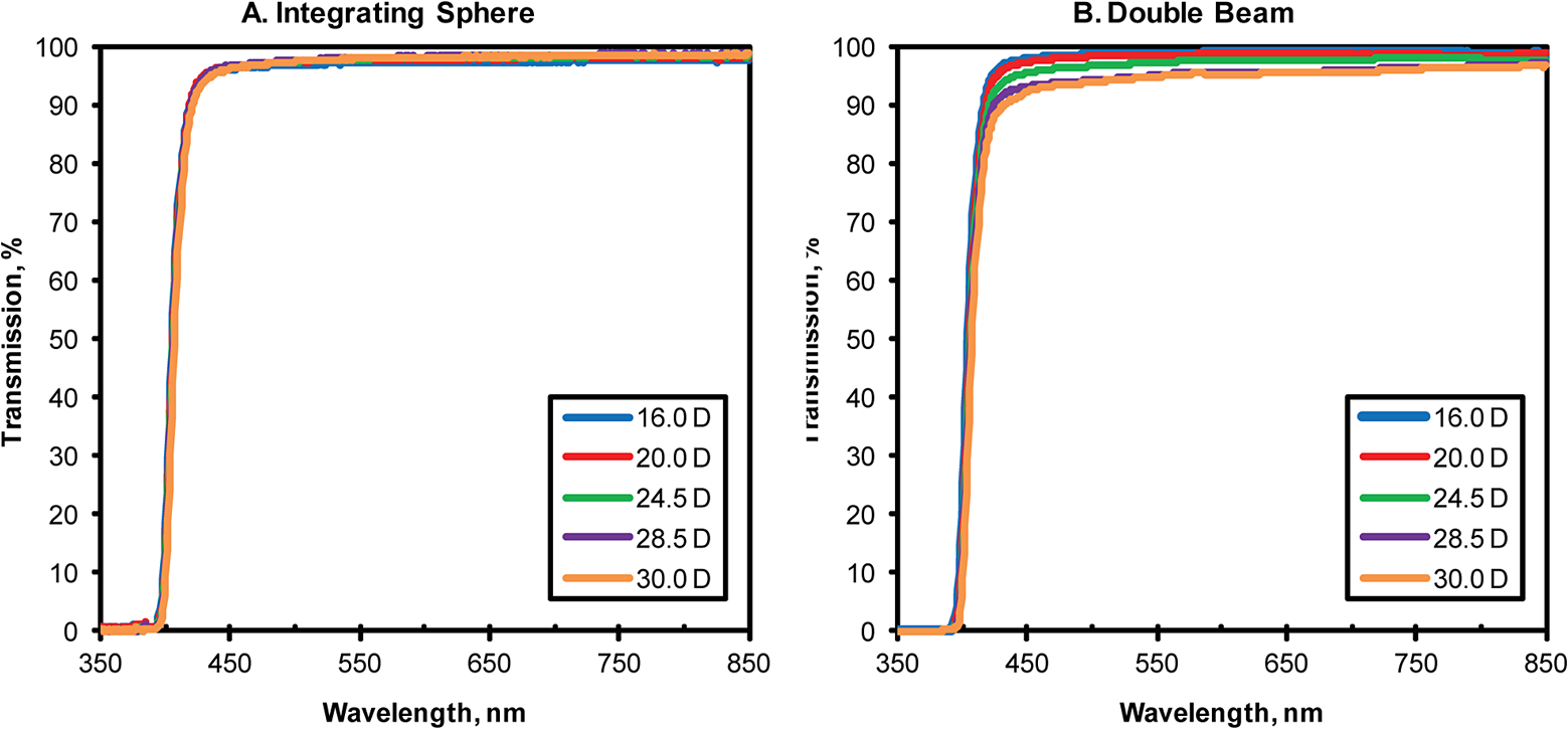 Table 3 shows a quantitative summary of these effects of lens power, measurement mode, and wavelength. Transmittance was considerably lower at shorter wavelengths for higher-powered IOLs when measured in the double-beam mode, as expected. For example, double-beam transmittance for the 16.0-D IOL decreased only from 99% at 850 nm to 97% at 450 nm, but double-beam transmittance for the 30.0-D IOL decreased from 97% at 850 nm to 92% at 450 nm. In contrast, transmission was fairly constant across power/wavelength combinations when measured by integrating sphere. Table 3Transmittance at a short wavelength (450 nm) and a long wavelength (850 nm) for intraocular lenses of varying power, measured in single-beam configuration with an integrating sphere and measured in double-beam configuration.
Measurement error is ±1%. 3.3.Effects of Lens Power on Transmittance (Modeled)Figure 4(a) shows how the calculated size of the beam on the detector in the vertical axis varied with IOL power. The beam size approached the detector size limit as the IOL power increased. The beam size became larger than the detector size with IOLs having power higher than 30 D. These calculations did not account for spherical aberration, misalignment, or tilting of the IOL; all of these factors would have spread the light energy of the beam over an even larger area. Fig. 4Calculated beam size on the detector as a function of labeled intraocular lens power, assuming lenses without spherical aberration and with perfect alignment. Calculations assumed that the beam was vertically collimated, was 5 mm in diameter, and had a wavelength of 450 nm. 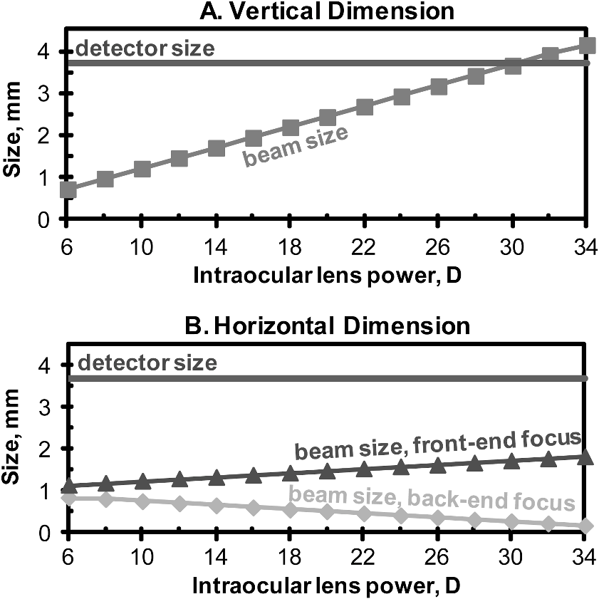 Figure 4(b) shows how the beam in the horizontal axis was converged at the sample cuvette position, where the minimum beam size was 1 mm. Because the beam could not be tightly focused at a single plane, the light source was treated as an extended source. Incident light was considered as a collection of beams that had foci that were continuously distributed over an extended range around the sample location. The beam foci were estimated to extend 23 mm in front of, and 23 mm to the back of, the sample position. Figure 4(b) shows how the beam size of the end-focusing components varied with IOL power in the horizontal axis. The front-end focusing beam became smaller with higher IOL power. Conversely, the back-end focusing beam became larger with higher IOL power. The size of the beam between two focusing ends would be represented by the area between the lines in Fig. 4(b). Overall, Fig. 4(b) shows that the beam size in the horizontal axis on the detector was small enough so that all energy was likely to be contained in the detector, even if spherical aberration and misalignments were added into the model. 3.4.Effects of Surface Light Scattering on TransmittanceThe surface light scattering values of the three explanted IOLs and their matched controls are shown in Table 1. The ultraviolet-visible spectra of the explanted IOLs are plotted in Fig. 5, which shows how the differences between integrating-sphere spectra and double-beam spectra became more prominent as the power of the IOLs increased. Figure 5(a) shows that ultraviolet-visible transmission for the low power (12.0-D) explanted IOL was similar when measured in either configuration (integrating sphere or double beam), consistent with the results of the modeling and measurements of low-power IOLs. Figure 5(b) shows that transmittance was slightly lower for the medium-power (21.0-D) explanted IOL when measured in double-beam configuration than in integrating-sphere configuration. Figure 5(c) shows that transmittance was much lower for the medium/high-power (23.0-D) explanted IOL when measured in double-beam configuration than in integrating-sphere configuration. Fig. 5Ultraviolet-visible transmission spectra of cleaned and hydrated clinically explanted IOLs and their control IOLs. Each curve represents the average of two to four spectra. 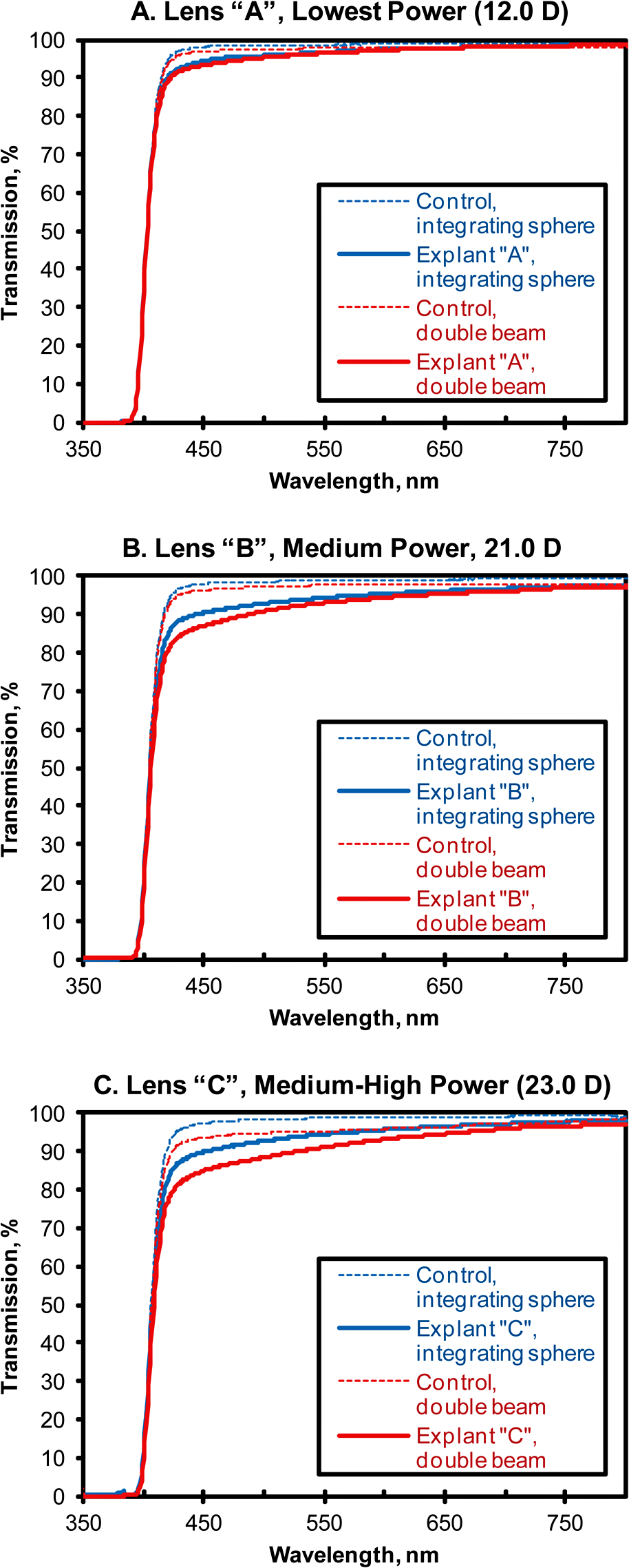 The results for the transmission of the IOLs at the selected wavelengths (450 and 550 nm) are tabulated in Table 4, which shows that higher transmission was detected by the integrating-sphere configuration than by the double-beam configuration for all IOLs. Differences between explanted IOLs and their controls were not as consistent: larger, equivalent, and smaller differences were detected when integrating-sphere mode was compared with double-beam mode. Larger differences between explanted IOLs and control IOLs occurred at 450 nm than at 550 nm in all cases, and ranged from 4% to 9%. Similarly, larger differences between double-beam mode and integrating-sphere mode occurred at 450 nm; these differences were 1% for the lowest-powered IOL, 3% for the medium-powered IOL, and 5% for the medium/high-powered IOL. Table 4Percentage transmission in at the selected wavelengths of 450 and 550 nm for explanted IOLs and their control IOLs.
3.5.Effects of Temperature on TransmittanceThe finished-goods inventory control IOLs of model MA60BM and having powers 16.0, 20.0, and 30.0 D had similar spectra when measured with an integrating sphere at ambient temperature or at 35°C. All between-temperature comparisons were similar within the experimental error ( transmission) at all wavelengths. The spectra of two of the explanted IOLs (explant C, medium power, and explant A, low power) also were measured at ambient temperature and at 35°C. For both explanted IOLs, spectra were within the experimental error ( transmission) when compared between temperatures at all wavelengths. 4.DiscussionObserved transmittance was considerably lower at shorter wavelengths, and higher at longer wavelengths, for high-powered IOLs measured in the double-beam mode. For example, the double-beam transmittance of the 30.0-D IOL decreased from 97% at 850 nm to 92% at 450 nm. These power-dependent, wavelength-dependent changes could be expected from optical properties of lenses. The refractive indices of IOLs decrease with increasing wavelength, leading to chromatic dispersion of focus, with different apparent optical powers for different wavelengths, as noted in the literature14,18 and as calculated in the current study (3.8 D of variation for the 30-D IOL). The measured wavelength-dependent changes in transmission of the 30-D IOL, for example, could be explained by the calculated change in lens power with wavelength, by the modeled vertical beam size after passing through a 30-D IOL (indicating that beam size would be as large as or larger than the detector), and by the knowledge that spherical aberration is worse with higher-power IOLs;19 all of these factors could have contributed to the measured loss of light at the detector in double-beam mode. Moreover, since our calculations did not account for spherical aberration, misalignment, or tilting of the IOL, our calculations could be considered a best-case scenario for double-beam measurements; even in the best case, the double-beam mode has serious limitations. Not only were integrating-sphere measurements consistent with varying lens power, they were consistent over varying temperature. Transmittance of IOLs did not change between 35°C and ambient temperature when measured with an integrating sphere. Therefore, keeping IOLs at the ambient temperature for transmission measurements not only is convenient and protective of the lens against temperature fluctuations, but also is a good approximation of transmission at physiological temperatures. Refractive indices are dependent on temperature,20 but the effect usually is small; in this study, any temperature-induced effects were not detectable when the integrating sphere was used. For IOLs with surface light scattering, higher transmission was detected by the integrating-sphere configuration than by the double-beam configuration in all three cases. Differences between explanted IOLs and their controls were not as consistent: larger, equivalent, and smaller differences were detected when integrating-sphere mode was compared with double-beam mode. The shapes of the spectra with reduced transmission were consistent with the etiology of surface light scattering: the nanovacuoles (subsurface nanoglistenings), as previously described.3 It is well known that scattering from small particles or vacuoles (presences or absences in a refractive medium) is higher at blue wavelengths than at red wavelengths, because small particles or vacuoles follow Raleigh-type scattering. The higher reduction of transmission in the bluer regions is most likely associated with subsurface nanoglistenings. The optical qualities of IOLs with surface light scattering will be examined in further detail in a forthcoming article, which will use only integrating-sphere measurements, per the conclusions of this study. Our current results, which were specific to our setup, should be generalizable to other double-beam spectrophotometers. Spectrophotometers in double-beam configuration have been widely used to measure transmittance of flat materials and solutions over a wide range of wavelengths. Our modeling and measurement results indicated that caution should be given to measuring an IOL in the double-beam configuration, since the optical power of the IOL may change the divergence of beam and may lead to significant energy loss on the detector, especially at high IOL powers. In double-beam configuration, the beam size on the detector would depend on the optical details of the system setup, such as distances between optical components, detector size, beam size, divergence of beam, and power of the IOL. The PerkiElmer Lambda is spectrophotometer in double-beam setup was used for our modeling and measurements, but similar conclusions would be expected for different configurations from different manufacturers. Because of variations in the transmittance measurements of IOLs when different spectrophotometer brands and different double-beam optical configurations are used, double-beam IOL transmittance cannot be easily compared between different studies. Unlike double-beam results, transmission spectra measured by integrating sphere should translate better across different laboratories. However, consistency of results from one type of integrating sphere to another was not tested in the current study. A Lab Sphere (PerkinElmer) 50-mm diameter integrating sphere was studied and was demonstrated to be superior to the double-beam mode, but integrating spheres from other manufacturers and with other diameters were not studied. For example, Oriel brand integrating spheres are available from Newport (Irvine, CA) with diameters of 51 to 203 mm. Whereas more research should be conducted to compare consistency of measurements from integrating spheres with various characteristics, the current study is valuable in establishing the general superiority of integrating spheres over double-beam methods for measuring the transmission of IOLs. In conclusion, our results indicated that transmittance measurements with integrating-sphere mode were consistent with varying lens power and over varying temperatures. A double-beam spectrophotometer may be useful for measuring total transmittance of lower-power IOLs (up to in our experimental setup, though a different optical setup spectrometer could have a different range). For higher-power IOLs ( in our setup), either the double-beam setup should be modified by incorporating a negative lens in the system or by changing the distance between the IOL and the photodetector, or an integrating sphere configuration should be used to eliminate variations due to spherical aberration and misalignment of IOLs. AcknowledgmentsAlcon is the employer of all authors. Alcon funded this study and provided the services of a medical writer for assistance with the preparation of this manuscript. ReferencesH. Matsushimaet al.,
“Analysis of surface whitening of extracted hydrophobic acrylic intraocular lenses,”
J. Cataract Refract. Surg., 35
(11), 1927
–1934
(2009). http://dx.doi.org/10.1016/j.jcrs.2009.07.004 JCSUEV 0886-3350 Google Scholar
S. Yoshidaet al.,
“Decreased visual function due to high-level light scattering in a hydrophobic acrylic intraocular lens,”
Jpn. J. Ophthalmol., 55
(1), 62
–66
(2011). http://dx.doi.org/10.1007/s10384-010-0901-2 JJOPA7 0021-5155 Google Scholar
M. Onget al.,
“Etiology of surface light scattering on hydrophobic acrylic intraocular lenses,”
J. Cataract Refract. Surg., 38
(2), 221
–226
(2012). http://dx.doi.org/10.1016/j.jcrs.2011.08.042 JCSUEV 0886-3350 Google Scholar
J. M. Artigaset al.,
“Spectral transmittance of intraocular lenses under natural and artificial illumination: criteria analysis for choosing a suitable filter,”
Ophthalmology, 118
(1), 3
–8
(2011). http://dx.doi.org/10.1016/j.ophtha.2010.06.023 0161-6420 Google Scholar
P. H. Ernest,
“Light-transmission-spectrum comparison of foldable intraocular lenses,”
J. Cataract Refract. Surg., 30
(8), 1755
–1758
(2004). http://dx.doi.org/10.1016/j.jcrs.2003.12.054 JCSUEV 0886-3350 Google Scholar
G. Romanoet al.,
“Colorimetric comparison of light-filtering intraocular lenses and human crystalline lenses at various ages,”
J. Cataract Refract. Surg., 37
(4), 758
–762
(2011). http://dx.doi.org/10.1016/j.jcrs.2010.10.053 JCSUEV 0886-3350 Google Scholar
L. Kesselet al.,
“Age-related changes in the transmission properties of the human lens and their relevance to circadian entrainment,”
J. Cataract Refract. Surg., 36
(2), 308
–312
(2010). http://dx.doi.org/10.1016/j.jcrs.2009.08.035 JCSUEV 0886-3350 Google Scholar
M. Tanitoet al.,
“Transmission spectrums and retinal blue-light irradiance values of untinted and yellow-tinted intraocular lenses,”
J. Cataract Refract. Surg., 36
(2), 299
–307
(2010). http://dx.doi.org/10.1016/j.jcrs.2009.08.036 JCSUEV 0886-3350 Google Scholar
C. BrockmannM. SchulzT. Laube,
“Transmittance characteristics of ultraviolet and blue-light-filtering intraocular lenses,”
J. Cataract Refract. Surg., 34
(7), 1161
–1166
(2008). http://dx.doi.org/10.1016/j.jcrs.2008.03.039 JCSUEV 0886-3350 Google Scholar
Ophthalmic implants—intraocular lenses—part 2: optical properties and test methods, International Organization for Standardization, Geneva, Switzerland
(2003). Google Scholar
American National Standard for Ophthalmic Optics—Intraocular Lenses, American National Standards Institute, Inc., Merrifield, VA
(2002). Google Scholar
Optics and optical instruments—contact lenses—determination of the spectral and luminous transmittance, International Organization for Standardization,
(1997). Google Scholar
H. FaublM. H. Quinn,
“Methods for determining ultraviolet transmission of UV-blocking contact lenses—Converging evidence, diverging views?,”
Int. Contact Lens Clin., 25
(5), 142
–148
(1998). ICCLEF Google Scholar
H. ZhaoM. A. Mainster,
“The effect of chromatic dispersion on pseudophakic optical performance,”
Br. J. Ophthalmol., 91
(9), 1225
–1229
(2007). http://dx.doi.org/10.1136/bjo.2007.118745 BJOPAL 0007-1161 Google Scholar
K. K. Sharma,
“Geometrical optics,”
Optics: Principles and Applications, 159
–216 Academic Press (Elsevier), Burlington, MA
(2006). Google Scholar
K. Miyataet al.,
“Comparison of postoperative surface light scattering of different intraocular lenses,”
Br. J. Ophthalmol., 93
(5), 684
–687
(2009). http://dx.doi.org/10.1136/bjo.2008.144691 BJOPAL 0007-1161 Google Scholar
K. Miyataet al.,
“Effect on visual acuity of increased surface light scattering in intraocular lenses,”
J. Cataract Refract. Surg., 38
(2), 221
–226
(2012). http://dx.doi.org/10.1016/j.jcrs.2011.08.042 JCSUEV 0886-3350 Google Scholar
D. SiedleckiH. S. Ginis,
“On the longitudinal chromatic aberration of the intraocular lenses,”
Optom. Vis. Sci., 84
(10), 984
–989
(2007). http://dx.doi.org/10.1097/OPX.0b013e318157ac82 OVSCET 1040-5488 Google Scholar
R. Raweret al.,
“Imaging quality of intraocular lenses,”
J. Cataract Refract. Surg., 31
(8), 1618
–1631
(2005). http://dx.doi.org/10.1016/j.jcrs.2005.01.033 JCSUEV 0886-3350 Google Scholar
J. T. Holladayet al.,
“Silicone intraocular lens power vs temperature,”
Am. J. Ophthalmol., 107
(4), 428
–429
(1989). AJOPAA 0002-9394 Google Scholar
|
||||||||||||||||||||||||||||||||||||||||||||||||||||||||||||||||||||||||||||||||||||||||||||||||||||||||||||||||||||||||||||||||||||||||||||||||||||||||||||||||||||||||||||||||||||||||||||||


