|
|
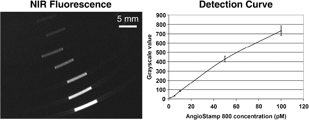
1.IntroductionNear-infrared (NIR) fluorescence imaging for intraoperative use has been widely studied over the last few years. This fact is well illustrated by the number of ongoing human clinical trials and the emergence of numerous companies aiming at commercializing this technology.1–10 Following these validation studies, the challenges for successfully reaching the clinic are twofold. The first challenge is the development of optimized targeted contrast agents and their translation to human trials. The second challenge is the design of optimized devices for surgery and their acceptance by the medical community.11–18 The two challenges must be addressed to discern the relevance of using NIR fluorescence, judged by the following metrics: clinical need, workflow integration, and cost-effectivenes, resulting in overall improvement of patient management. We are interested in the design and acceptance of devices optimized for surgery. Most clinical NIR fluorescence imaging systems to date are meant for large open surgeries where structures of interest are easily accessible.3,4,6,7,9 In many other procedures, however, the structure of interest is not readily accessible, such as inside the oral cavity for oral cancer surgery, and the design of current systems precludes access in many ways. Mechanically, the footprint of such systems is excessive and results in blocking visual and manual access. Optically, the illumination and image collection fail to detect fluorescence efficiently within small cavities. Therefore, it is necessary to miniaturize the imaging system while preserving good fluorescence imaging quality to provide surgeons with adequate tools to perform surgery. Recent work has been performed to miniaturize fluorescence imaging systems.19–24 In particular, work from Wang et al.21 presents the design of a compact NIR fluorescence imaging system used for preclinical imaging. Similarly, work from Shin et al.22 presents a small-form-factor fluorescence microscope used for oral cancer diagnosis. However, to date, no optimized clinically compatible miniaturized fluorescence imaging system has been described. In this study we propose the design of a novel fluorescence imaging system that has been miniaturized and optimized for use during oral oncologic procedures in humans. The system, termed FluoSTIC, takes advantage of a novel, high-quality, small-form-factor, lipstick camera for collecting fluorescence light. A novel and innovative cylindrical optical fiber array has been developed and optimized to guarantee good field illumination homogeneity. A novel fiber-based illumination system that combines both NIR excitation and white light illumination is proposed and tested. A novel filtration scheme optimizing the fluorescence collection as opposed to fluorescence excitation is proposed and tested. Importantly, the system has been designed to meet requirements necessary for successful clinical use. Finally, the system has been characterized on the bench and validated in a preclinical model for oncologic surgery. 2.Materials and Methods2.1.RequirementsGiven that the scope of our intended clinical application is head and neck oncologic surgery, it is imperative to miniaturize the imaging system so that it does not hinder the surgeon from either visually or manually accessing the surgical area. In collaboration with our surgeons, we specified that the fluorescence imaging system should be less than 25 mm in outer diameter and less than 250 mm in length to permit ergonomic use while providing image guidance during the surgical intervention. In addition, we specified a working distance greater than 100 mm and a field of view of 30 to 50 mm as our target for the imaging system. These specifications were defined through discussions with our surgeons, through testing of mock-ups for the size requirement, and from experience in using image-guidance systems for surgery for all other parameters. One of the most challenging tasks in miniaturizing the system and its components consists in maintaining good fluorescence detection performances. Figure 1 depicts the essential components of a fluorescence imaging system and their associated key parameters. A comprehensive review of all parameters related to fluorescence imaging has already been published15; therefore, for the purpose of this study, we provide an analysis of every single component to create the most efficient system possible within the constraints of the required footprint. Because the medium composition and the fluorophore are out of the scope of this study, we will focus on the camera, the objective lens, the illumination, and the filtration. Fig. 1Schematics of typical fluorescence imaging system and its key parameters. A typical system is composed of a light source exciting a fluorophore within a diffusive medium. The fluorescence out of the medium is separated from the excitation light using an emission filter, collected by an objective lens, and imaged on a camera sensor. Particular attention to the parameters of each component is required to optimize the imaging system for best performance. 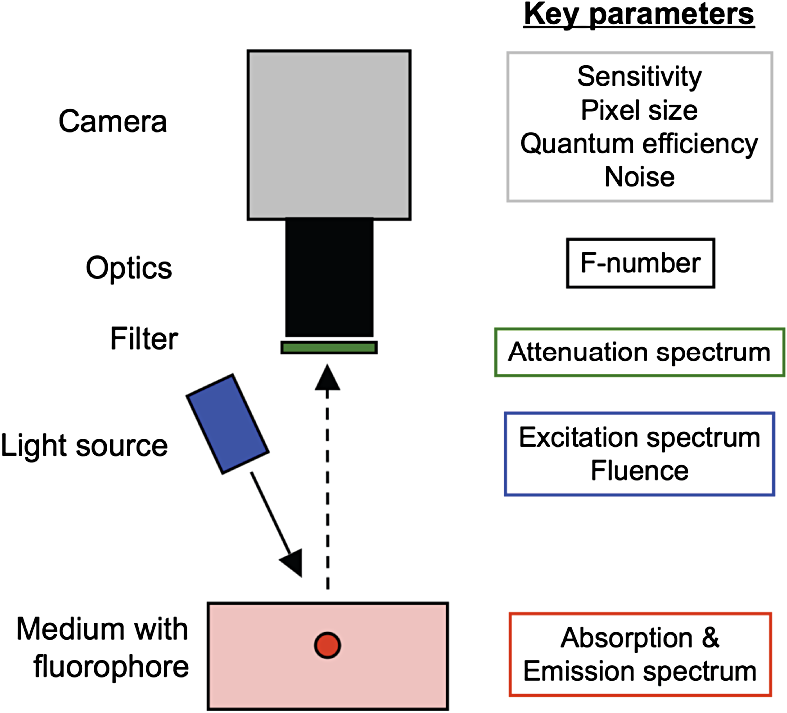 2.2.CameraBecause of its electronics, the camera is undoubtedly the most difficult to miniaturize while maintaining acceptable performance for NIR fluorescence imaging. Of paramount importance are its sensitivity and noise, particularly because fluorescence imaging remains a low-light technique. We tested many miniature cameras; whereas current miniaturized technology is mainly based on complementary metal oxide semiconductor (CMOS) sensors, their noise precludes their use as a camera for fluorescence imaging. The use of a “lipstick,” cylindrical geometry charge-coupled device (CCD) camera is therefore the only off-the-shelf solution that offers a small size factor along with good sensor performance. The CM-030GE-RH (Jai, Denmark) is a 17-mm-diameter camera with a one-third inch monochrome CCD sensor and a resolution of that offers a maximum frame rate of 120 fps with up to 10 bits dynamic range. Given its size and performance, this camera was chosen as the base of our miniaturized imaging system. 2.3.ObjectiveThe objective lens plays a crucial role in photon collection efficiency and imaging quality. It is a general belief that low-light systems require large apertures (low F/#) to allow more photons to be collected. Although this is generally true for most reflectance imaging, it is not always justified with fluorescence imaging, particularly when using a commercially available objective lens as in image-guided surgery. Because emission filters are necessary to eliminate a very strong fluorescence excitation light comparatively to the fluorescence signal, the system efficiency greatly depends on the quality of the filtration (discussed in detail in the next section). To achieve this quality in filtration, a large aperture system cannot rely solely on interference filters (the most efficient filters available) because a large aperture induces larger photon angles in the collection path when interference filters usually block efficiently only up to 10 deg of incidence maximum [Fig. 2(a), left]. Therefore, while collection efficiency is high at the aperture level, either filtration quality is impacted and imaging quality is poor, or colored glass filters must be used, greatly reducing the overall transmission of the filtration system. On the other hand, a small aperture system can be efficiently used with interference filters but with a lower efficiency in collection through a small aperture [Fig. 2(a) right]. From our experience, both the combination of large aperture with colored glass and the combination of small aperture with interference filters perform similarly, with a slight advantage for the small aperture/interference filters approach. Note that in our case, with a long working distance, there is a filtration efficiency advantage in placing the filter at the front of the objective lens, where photon angles are less important than at the back of the objective. Additionally, if one has resources to design and fabricate a custom objective lens, an alternative approach is to place the filter inside the objective lens within a collimated beam path. This is, however, not possible when using inexpensive, commercially available objectives. Fig. 2Collection strategy. (a), Schematics of the two principal approaches for collection. Left: Low F/#: the diaphragm aperture is wide open, leading to high collection efficiency but large angles in the collection light path and shallow depth of field. Right: High F/#: the diaphragm aperture is narrow, leading to low collection efficiency but small angles in the collection light path and large depth of field. (b), Table summarizing the two principal approaches for collection. Left column: Low F/# (large aperture). Right column: High F/# (small aperture). Overall, both strategies perform similarly, but the depth of field using a small aperture system provides more ergonomic use during surgery.  An important parameter for ergonomic use of image-guided open-surgery systems is the depth of field. Because small apertures result in large depth of field, such systems are greatly preferred to create ergonomic systems that can be used efficiently in realistic clinical conditions. In our case, the CM-030GE-RH camera comes with a series of 17-mm-diameter objectives (7.5, 15, and 24 mm focal) with controllable aperture. Given our field-of-view requirement, we chose the OP-715 (Jai, Denmark), a 15-mm focal objective lens, and adjusted it to for efficient use with the interference filters and to provide a large depth of field for ergonomic clinical use. 2.4.FiltrationAs outlined above, most of the difficulty in creating an efficient fluorescence imaging system is regarding the design of an efficient filtration scheme that isolates excitation and emission light. Most imaging systems created for image-guided surgery focus on exciting the fluorophore at its peak absorption and collecting only a fraction of the emitted photons. Another strategy is to excite the fluorophore in a less efficient portion of its absorption spectrum and to collect all emitted photons, as illustrated in Fig. 3(a). To compare both strategies, we conducted a quick analysis by computing separately the excitation efficiency and the collection efficiency of two optically similar imaging systems with two different filtration schemes. The first filtration scheme (termed FluoSTIC) employed a 740-nm laser excitation and a 772- to 857-nm emission. The second filtration scheme (termed typical system) employed a 785-nm laser excitation and a 808- to 900-nm emission. Excitation efficiency was calculated by multiplying at each point the source spectrum (5 nm wide here) with the indocyanine green (ICG) absorption spectrum and integrating the result over the spectral range. Collection efficiency was calculated by performing the same operation with the emission filter transmission spectrum, the ICG emission spectrum, and the typical CCD spectral response. Finally, the overall efficiency was obtained by multiplying the excitation and the emission efficiencies [Fig. 3(b)]. As expected, excitation efficiency was determined to be 2.2% for FluoSTIC and 4.6% for a typical system, and collection efficiency was determined to be 9.7% for FluoSTIC and 3.0% to 7.5% for a typical system, depending on the approach (3.0% for large aperture with a combination of interference and absorption filters; 7.5% for small aperture with interference filters). On average, the FluoSTIC filtration approach performs similarly to a typical system. Of note, the wider collection band accommodates more NIR fluorophores, especially the new generation of dyes that are typically more blue-shifted.18 It should also be noted that in most cases the intensity of the light source can be increased to compensate for the loss in absorption by the fluorophore. Fig. 3Filtration strategy. (a), FluoSTIC filtration strategy illustrating the choice of exciting at lower wavelength (blue curve) and collecting more fluorescent light (green curve). Note the ICG absorption spectrum (dashed orange curve), the ICG emission spectrum (dashed crimson curve), and the white light filter (red curve). (b), Table summarizing the two principal approaches for filtration. Left column: Excitation and collection efficiencies when privileging the collection of the emitted fluorescence. Right column: Excitation and collection efficiencies when privileging the excitation of the NIR fluorophore.  The filtration scheme of FluoSTIC is depicted in Fig. 3(a) and accommodates an excitation filter centered at 740 nm (blue curve: FF01-740/13-25, Semrock, NY) that excites ICG with a 40% efficiency (dashed orange curve) as well as an emission filter from 772 to 857 nm (green curve: HQ815/85, Chroma, VT) that collects most ICG emitted photons (dashed crimson curve). For optimal isolation of the excitation and emission channels, the optical densities (OD) of the excitation and emission filters cross at OD . Because the FluoSTIC imaging system also has the option to provide NIR-depleted white light, we overlaid the white-light filter transmission spectrum (red curve: ET710spxt, Chroma, VT) in Fig. 3(a). 2.5.Sources and IlluminationWe used an sub miniature A (SMA)-coupled 500-mW, 740-nm laser diode from Power Technology (model# IQ1A) as our NIR light source and an SMA-coupled 7-mW cold (5600 K) white LED from Thorlabs (model# MCWHF1). As previously reviewed, two main approaches are available for illumination: local and remote.15 Due to the footprint constraint, the only solution available was remote illumination, in which the sources are located outside of the imaging system and fibers are used to transport light from the sources to the imaging head. We chose a multifiber bundle approach, where both sources (NIR and white light) are combined using a custom-made coupler into a circular array at the bottom end of the imaging system. Figure 4(a) illustrates the concept of the circular fiber array in a cross-section view. The camera is positioned within circular rings that hold the illumination fibers. Fig. 4Illumination design. (a) Concept of the circular fiber array design for illumination control in a cross-section view. The camera is positioned within circular rings that hold the illumination fibers. The bottom ring controls the exit angle of the fibers. (b), Line profile of the field irradiance at various fiber exit angles simulated by ray tracing using OptisWorks. Note that an exit angle of 3 deg seems optimal for illumination flatness in our geometry. (c), Actual line profile measured with the FluoSTIC system. Note that the effective exit angle has been independently measured to be 1 deg. The measurement and the simulation match closely at that exit angle.  To provide the highest NIR fluorescence imaging quality possible, controlling the illumination profile is of paramount importance. We chose to control the exit angle of the fibers and simulated the illumination profile using OptisWorks (Optis, France). OptisWorks is an add-in to SolidWorks (Dassault Systèmes S.A., France) that allows 3-D ray tracing in opto-mechanical designs. An 18-mm ring containing 19 optical fibers was created in SolidWorks with various exit angles [from 0 to 5 deg, as defined in Fig. 4(a)] and irradiance from a 1-W source simulated at a 10-cm working distance. Line profiles were extracted and are plotted in Fig. 4(b). The optimal exit angle for maximum field flatness was determined to be 3 deg. Of note, such solution relies on the fact that fibers conserve the angle of light from input to output, provided that it fits the numerical aperture of the fibers. To produce homogeneous and efficient illumination, the design of the coupler is of paramount importance. Briefly, as shown in Fig. 5, it involves an afocal design with three lenses (L1, L2, and L3: F240SMA, Thorlabs, NJ), a dichroic mirror (M: FF705, Semrock, NY), and a light shaping diffuser (D: 10 deg, Luminit, CA) to ensure optimal injection of the light into the common end of the bundle. Note the presence of a NIR excitation filter (F1: FF01-740/13-25, Semrock, NY) and of a white-light filter (F2: ET710spxt, Chroma, VT). The main purpose of this injection system is to ensure that all fibers at the common end are homogenously illuminated. Fig. 5Coupler design. An afocal design with 3 lenses (L1, L2, and L3), a dichroic mirror (M), and a light shaping diffuser (D) ensures optimal injection of the light into the common end of the bundle. Note the presence of a NIR excitation filter (F1) and of a white light filter (F2).  The fluorescence imaging performances were assessed using AngioStamp™ 800 (Fluoptics, France) diluted in DMSO at 5 different concentrations: 1, 5, 10, 50, and 100 pM. Small volumes of 30 μL were injected into 2-mm-diameter capillaries for each concentration and imaged by the system at its nominal working distance with a 10-ms exposure time. 2.6.In Vivo ValidationSmall tumor-positive nodules that resemble peritoneal carcinomatosis were induced by injecting 500,000 TSA-pGL3 cells diluted in PBS to athymic nude mice and detected by the intravenous injection of an NIR contrast agent, RAFT RGD IRD800 (AngioStamp™ 800) at 35 μM in 200 μL. The procedure has been described in detail previously.16 Image-guided detection of the NIR-positive nodules was performed using the FluoSTIC imaging system with the organs externalized and imaged on black paper. All animal experiments were conducted in agreement with the Principles of Laboratory Animal Care (National Institutes of Health pub. no. 86–23, revised 1985) and approved by the regional ethics committee. Female athymic Swiss nude mice (Janvier, Le Genest-Isle, France) were used in this study and maintained under specific pathogen-free conditions. 3.Results3.1.FluoSTICThe fiber bundle assembly was designed and fabricated by Fiber Tech Optica (Kitchener, ON). As shown in Fig. 6, 1-to-19 fiber bundles composed of individual 300-μm, 0.37NA fibers were spaced equally on three 1.5-mm-thick rings with a 17-mm inner diameter. Note that a mock-up of the camera used for the multifiber ring design can be seen inserted within the rings in the bottom left figure. With proper coupling at the common end (Fig. 5), every single bundle was homogeneously filled with light as evidenced with green light in Fig. 6. Using this multifiber ring approach, along with a 500-mW, 740-nm laser source, the system is capable of illuminating the field with a fluence rate of and meets the requirement of a class 1 laser. The CM-030GE-RH camera from Jai, Denmark, was inserted behind the rings, slid into position, and secured using screws located on the brass rings. Figure 7(a) shows schematics of the assembled imaging system. Figure 7(b) shows an actual picture of FluoSTIC, along with its housing. The emission filter was placed at the bottom of the objective lens. Fig. 6Multifiber ring design. The imaging system illumination is based on a small footprint, circular ring approach. A 1-to-19 multifiber bundle is used to transport NIR excitation light and white light from the coupler to the rings. Every single fiber is equally spaced at the bottom ring of the system. This approach allows for minimal footprint while ensuring homogeneous safe illumination (class 1 laser). Note that a mock-up of the camera used for the multifiber ring design can be seen inserted within the rings in the bottom left figure. 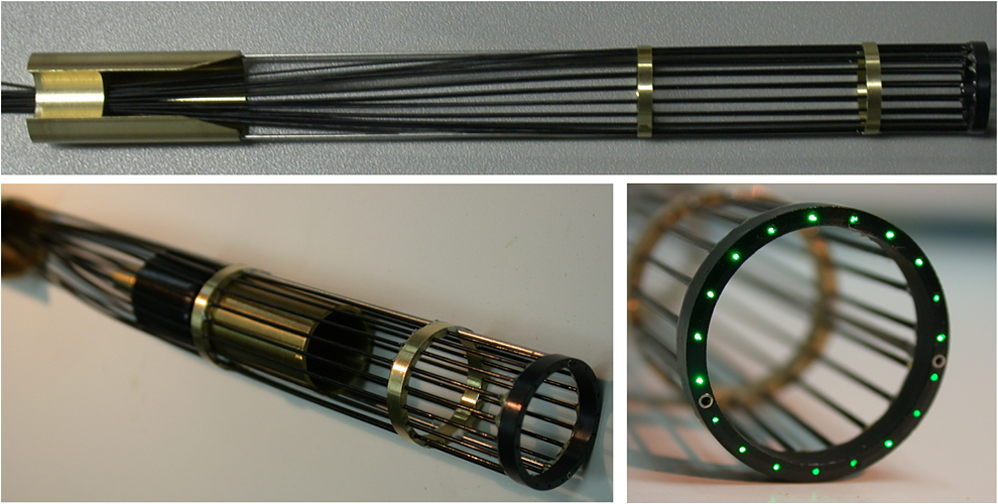 Fig. 7FluoSTIC. (a), Schematic of all the components of the FluoSTIC fluorescence imaging system. The camera is inserted inside the illumination rings. The emission filter is placed at the bottom of the imaging lens. The body of the system is then placed over the whole assembly. (b), Pictures of the FluoSTIC imaging system. Left: Camera with filter inside the multifiber ring. Right: Housing protecting the device. A US quarter is shown in between the two. 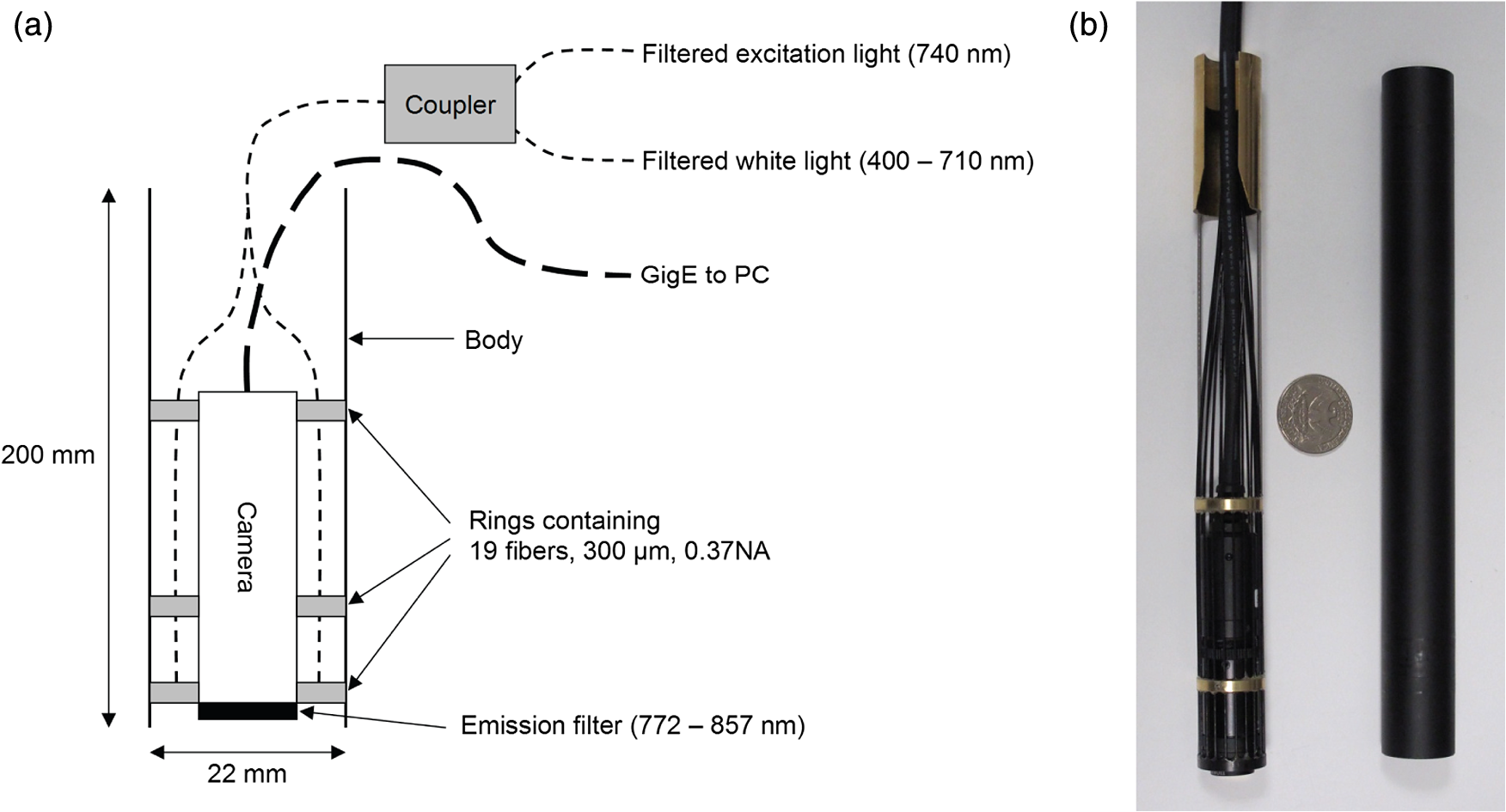 3.2.Specifications and TestsOverall, as summarized in Table 1, FluoSTIC measures only 22 mm in diameter (including the housing) and 200 mm in length and weighs 180 g. The system is capable of imaging a field of view at a 126-mm working distance with of NIR excitation light and 1000 lux of white light. The system has been certified as a class 1 laser device. The system resolution was measured to be 70 μm and the depth of field 20 mm using the 1951 USAF resolution test chart. The camera resolution is , with a 10-bit dynamic range and an exposure time adjustable from 32.5 μs to 2 s. Custom software was written in Labview (National Instruments, Austin, TX) and run on a Pentium 4 computer. Table 1FluoSTIC imaging system specifications.
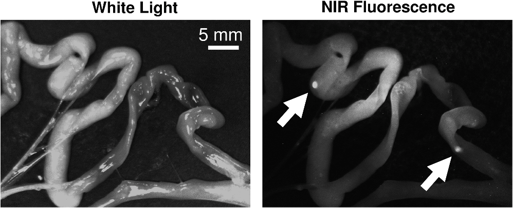
The illumination field flatness was measured and the line profile is shown in Fig. 4(c). It is interesting to note that the third ring that provides the exit angle value to the fibers [Fig. 4(a)] was fabricated with an effective exit angle of 1 deg (measured independently). The profile measured closely matches the one from the OptisWorks simulation, proving that it could be a reliable tool for designing optimized illumination systems. The results from the fluorescence imaging performance tests are presented in Fig. 8. As expected, good image quality with very low background and good linearity in the system is observed over the dynamic range of the camera. The detection sensitivity is comparable to other reported values from large-size, state-of-the-art fluorescence imaging systems15 but with the advantage of a much smaller footprint. This fact has been experimentally verified during various procedures, as there exist to date no direct performance comparisons of NIR fluorescence imaging devices. A commonly used metric to compare the performance between NIR fluorescence imaging systems is the exposure time in similar procedures. FluoSTIC has been used in three main procedures to date: fluorescence angiography on animals with exposures in the order of 50 to 100 ms, tumor detection on animals with exposures in the order of 100 to 200 ms, and ex vivo human liver cancer imaging with exposures of less than 10 ms. Such exposure times are similar to other large-size, state-of-the-art systems such as the ones reviewed in Ref. 15. 3.3.In Vivo ValidationFluoSTIC was validated in vivo during the image-guided detection and excision of small positive nodules in the peritoneal cavity of mice. Figure 9 shows the results obtained with the imaging system by acquiring sequentially white light images (left, white light filter off) and NIR fluorescence (right, white light filter on). Positive nodules are clearly visible, as indicated by the white arrows, and could easily be detected and excised during surgery. 4.DiscussionAs the field of image-guided surgery evolves, technological advances will be needed to address new concerns in the field. As mentioned previously, the size of the system used during head and neck surgery is a major constraint. Miniaturization of this technology is one way to develop novel applications to address this issue or other issues with endoscopy in the future. In this work we present our efforts to push the technology to its limits and provide the best image quality possible within a small footprint. Such an approach required us to reconsider all key parameters to design the most efficient system within our size constraints. The optical design (camera, lenses, filtration) and the mechanical design (multifiber ring) have been optimized to provide the best results possible for ergonomic (small size, large depth of field) and versatile (various 800-nm contrast agents) imaging in the clinic. This includes a small-form-factor, 10-bit CCD camera, a high F/# objective, a versatile filtration scheme, and a cylindrical illumination design. One major constraint when developing a clinical imaging system is regarding deployment in an operating room. This constraint is multifold, including ergonomics, safety, regulations, and acceptance by healthcare professionals.15 In our case, we focused on ergonomics to provide a system that could easily be integrated within the surgical workflow through its small size and high NIR imaging performance. We also paid significant attention to safety and system design for future clinical translation. Owing to the distributed source approach, our system has been certified class 1 laser, the safest class not requiring patients and clinicians to wear protection goggles. Second, the system body was designed to meet the IP64 water-sealed class, allowing easy decontamination. Third, a sterile drape bonded to a sterile acrylic shield (not shown here) was designed to fit over the system and guarantee sterility during the procedure. In addition, we paid significant attention to the system design and documentation to facilitate the process of obtaining CE marking and FDA approval in the future. Particularly, this includes following IEC60601 guidelines for electrical safety, IEC60825 for optical safety, as well as carefully documenting the design and validation process. Overall, all the necessary documentation has been prepared to facilitate the elaboration of standard operating procedures for receiving, assembling, and testing, as well as allowing component and system traceability. Efficiently operating during surgery requires the use of bright NIR-depleted white light, whose design has to meet the standards for surgical luminaries as defined in IEC60601 guidelines for minimum intensity, light color, and illumination profile. Providing such white light under our footprint constraints is challenging; however, we believe this specification is achievable and will make this goal the focus of later work. The system presented here employs a white light source with a removable low-pass filter that permits anatomic information of the sample in a monochromatic fashion to be provided. Other possible implementations involve pulsing alternatively white light illumination for monochromatic anatomic display (or pulsed red, green, blue for color anatomic display) and NIR illumination for fluorescence information while synchronizing camera acquisition as explained in the recent article from Gray et al.25 The advantage of the chosen solution is that visible white light illumination is always present on the surgical field with the option of choosing NIR fluorescence or white light imaging by switching the filter on or off. Finally, an alternative solution could be the use of a custom Bayer filter (red, green, blue and NIR) for simultaneous visible and NIR fluorescence imaging. Each solution inherently has a tradeoff between sensitivity and time of acquisition. Finally, the fact that the system employs an SMA-coupled illumination design allows for its use out of the NIR range. In particular, endogenous fluorescence using UV-blue illumination has been widely investigated for head and neck applications.26–29 The imaging system described here could be easily accommodated for use in other applications that employ different sources. Another great advantage of this system is its simplicity: FluoSTIC has few parts, is easy to assemble, and costs less than $10,000 in parts. 5.ConclusionsWe designed, fabricated, and tested a miniature fluorescence imaging system optimized for 800-nm NIR fluorescence imaging. This system employs a miniature CCD 10-bit camera, a high F/# objective for large depth of field and efficient filtration, a versatile filtration scheme allowing the imaging of several 800 nm fluorescence dyes, and an innovative illumination ring approach that allows efficient illumination of the field of view with high fluence while preserving a small footprint. The system is also safe (class 1 laser). Overall, the system measures 22 mm in diameter and 200 mm in length and weighs less than 200 g, and performs similarly to other reported state-of-the-art fluorescence imaging systems. This study lays the foundation for the clinical translation of optimized fluorescence imaging systems for image-guided surgery. AcknowledgmentsThe authors thank Veronique Birkenheier for administrative assistance and Lindsey Gendall and David Burrington, Jr., for editing. The authors thank the following individuals for their contributions to the project: from CEA-LETI, Cedric Allier, Anne Planat-Chretien, and Vincent Poher; from Fluoptics, Philippe Rizo and Norman Mangeret; from Chroma, Kelly Stockwell; from Fiber Tech Optica, Jeff Dupuis and Rafal Pawluczyk. This study was funded by a Contrat Plan Etat Region (CPER, France). ReferencesE. M. Sevick-Muracaet al.,
“Imaging of lymph flow in breast cancer patients after microdose administration of a near-infrared fluorophore: feasibility study,”
Radiology, 246
(3), 734
–741
(2008). http://dx.doi.org/10.1148/radiol.2463070962 RADLAX 0033-8419 Google Scholar
T. Ishizawaet al.,
“Real-time identification of liver cancers by using indocyanine green fluorescent imaging,”
Cancer, 115
(11), 2491
–2504
(2009). http://dx.doi.org/10.1002/cncr.v115:11 60IXAH 0008-543X Google Scholar
D. Murawaet al.,
“Sentinel lymph node biopsy in breast cancer guided by indocyanine green fluorescence,”
Br. J. Surg., 96
(11), 1289
–1294
(2009). http://dx.doi.org/10.1002/bjs.v96:11 BJSUAM 0007-1323 Google Scholar
S. L. Troyanet al.,
“The FLARE intraoperative near-infrared fluorescence imaging system: a first-in-human clinical trial in breast cancer sentinel lymph node mapping,”
Ann. Surg. Oncol., 16
(10), 2943
–2952
(2009). http://dx.doi.org/10.1245/s10434-009-0594-2 1068-9265 Google Scholar
K. Wasedaet al.,
“Intraoperative fluorescence imaging system for on-site assessment of off-pump coronary artery bypass graft,”
JACC Cardiovasc. Imaging, 2
(5), 604
–612
(2009). http://dx.doi.org/10.1016/j.jcmg.2008.12.028 Google Scholar
C. Hircheet al.,
“ICG fluorescence-guided sentinel node biopsy for axillary nodal staging in breast cancer,”
Breast Cancer Res. Treat., 121
(2), 373
–378
(2010). http://dx.doi.org/10.1007/s10549-010-0760-z BCTRD6 Google Scholar
T. Hojoet al.,
“Evaluation of sentinel node biopsy by combined fluorescent and dye method and lymph flow for breast cancer,”
Breast, 19
(3), 210
–213
(2010). Google Scholar
B. T. Leeet al.,
“The FLARE intraoperative near-infrared fluorescence imaging system: a first-in-human clinical trial in perforator flap breast reconstruction,”
Plast. Reconstr. Surg., 126
(5), 1472
–1481
(2010). http://dx.doi.org/10.1097/PRS.0b013e3181f059c7 PRSUAS 0032-1052 Google Scholar
J. S. Mieoget al.,
“Toward optimization of imaging system and lymphatic tracer for near-infrared fluorescent sentinel lymph node mapping in breast cancer,”
Ann. Surg. Oncol., 18
(9), 2483
–2491
(2011). http://dx.doi.org/10.1245/s10434-011-1566-x 1068-9265 Google Scholar
G. M. van Damet al.,
“Intraoperative tumor-specific fluorescence imaging in ovarian cancer by folate receptor-alpha targeting: first in-human results,”
Nat. Med., 17
(10), 1315
–1319
(2011). http://dx.doi.org/10.1038/nm.2472 1078-8956 Google Scholar
L. Balacumaraswamiet al.,
“A comparison of transit-time flowmetry and intraoperative fluorescence imaging for assessing coronary artery bypass graft patency,”
J. Thorac. Cardiovasc. Surg., 130
(2), 315
–320
(2005). http://dx.doi.org/10.1016/j.jtcvs.2004.11.033 JTCSAQ 0022-5223 Google Scholar
J. V. Frangioni,
“The problem is background, not signal,”
Mol. Imaging, 8
(06), 303
–304
(2009). MIOMBP 1535-3508 Google Scholar
H. S. Choiet al.,
“Tissue-and organ-selective biodistribution of NIR fluorescent quantum dots,”
Nano Lett., 9
(6), 2354
–2359
(2009). http://dx.doi.org/10.1021/nl900872r NALEFD 1530-6984 Google Scholar
E. A. te Veldeet al.,
“The use of fluorescent dyes and probes in surgical oncology,”
Eur. J. Surg. Oncol., 36 6
–15
(2010). Google Scholar
S. GiouxH. S. ChoiJ. V. Frangioni,
“Image-guided surgery using invisible near-infrared light: fundamentals of clinical translation,”
Mol. Imaging, 9
(5), 237
–255
(2010). MIOMBP 1535-3508 Google Scholar
M. Keramidaset al.,
“Intraoperative near-infrared image-guided surgery for peritoneal carcinomatosis in a preclinical experimental model,”
Br. J. Surg., 97
(5), 737
–743
(2010). http://dx.doi.org/10.1002/bjs.6986 BJSUAM 0007-1323 Google Scholar
J. S. Mieoget al.,
“Novel intraoperative near-infrared fluorescence camera system for optical image-guided cancer surgery,”
Mol. Imaging, 9
(4), 223
–231
(2010). MIOMBP 1535-3508 Google Scholar
H. S. Choiet al.,
“Synthesis and in vivo fate of zwitterionic near-infrared fluorophores,”
Angew. Chem., 50
(28), 6258
–6263
(2011). http://dx.doi.org/10.1002/anie.201102459 ANCEAD 0044-8249 Google Scholar
C. F. Pohet al.,
“Direct fluorescence visualization of clinically occult high-risk oral premalignant disease using a simple hand-held device,”
Head Neck, 29
(1), 71
–76
(2007). http://dx.doi.org/10.1002/(ISSN)1097-0347 HEANEE 1097-0347 Google Scholar
D. Roblyeret al.,
“Multispectral optical imaging device for in vivo detection of oral neoplasia,”
J. Biomed. Opt., 13
(2), 024019
(2008). http://dx.doi.org/10.1117/1.2904658 JBOPFO 1083-3668 Google Scholar
X. Wanget al.,
“Compact instrument for fluorescence image-guided surgery,”
J. Biomed. Opt., 15
(2), 020509
(2010). http://dx.doi.org/10.1117/1.3378128 JBOPFO 1083-3668 Google Scholar
D. Shinet al.,
“A fiber-optic fluorescence microscope using a consumer-grade digital camera for in vivo cellular imaging,”
PLoS One, 5
(6), e11218
(2010). http://dx.doi.org/10.1371/journal.pone.0011218 1932-6203 Google Scholar
K. K. Ghoshet al.,
“Miniaturized integration of a fluorescence microscope,”
Nat. Methods, 8
(10), 871
–878
(2011). http://dx.doi.org/10.1038/nmeth.1694 1548-7091 Google Scholar
Y. Liuet al.,
“Hands-free, wireless goggles for near-infrared fluorescence and real-time image-guided surgery,”
Surgery, 149
(5), 689
–698
(2011). http://dx.doi.org/10.1016/j.surg.2011.02.007 SURGAZ 0039-6060 Google Scholar
D. C. Grayet al.,
“Dual-mode laparoscopic fluorescence image-guided surgery using a single camera,”
Biomed. Opt. Express, 3
(8), 1880
–1890
(2012). http://dx.doi.org/10.1364/BOE.3.001880 BOEICL 2156-7085 Google Scholar
P. M. Laneet al.,
“Simple device for the direct visualization of oral-cavity tissue fluorescence,”
J. Biomed. Opt., 11
(2), 024006
(2006). http://dx.doi.org/10.1117/1.2193157 JBOPFO 1083-3668 Google Scholar
C. F. Pohet al.,
“Fluorescence visualization detection of field alterations in tumor margins of oral cancer patients,”
Clin. Cancer Res., 12
(22), 6716
–6722
(2006). http://dx.doi.org/10.1158/1078-0432.CCR-06-1317 CCREF4 1078-0432 Google Scholar
M. C. PierceD. J. JavierR. Richards-Kortum,
“Optical contrast agents and imaging systems for detection and diagnosis of cancer,”
Int. J. Cancer, 123
(9), 1979
–1990
(2008). http://dx.doi.org/10.1002/ijc.v123:9 IJCNAW 1097-0215 Google Scholar
D. Roblyeret al.,
“Objective detection and delineation of oral neoplasia using autofluorescence imaging,”
Cancer Prev. Res. (Phila.), 2
(5), 423
–431
(2009). http://dx.doi.org/10.1158/1940-6207.CAPR-08-0229 1940-6207 Google Scholar
|