

|
|
|
Photoacoustic (PA) imaging has gained great attention in biomedicine because of its unique combination of strong optical absorption contrast and high ultrasonic resolution.1,2 The PA imaging domain can flexibly cover from a microscopic regime (submicrometer or micrometer scale) to a macroscopic regime (centimeter scale) based on a single common signal generation platform (i.e., optical absorption contrast).3,4 In the microscopic regime, optical-resolution photoacoustic microscopy (OR-PAM) has successfully provided in vivo morphological, functional, and molecular information of tissues.5–7 The key hardware specification of OR-PAM is the high lateral resolution (on the order of micrometer) and fair penetration depth (), and no ultrahigh-frequency ultrasonic transducer () is required. Similar to pure optical microscopic imaging modalities including fluorescence confocal microscopy, multiphoton microscopy, and optical coherence tomography, the lateral resolution of OR-PAM has been determined by the tight optical focusing capability using an optical objective.8 In contrast to those all-optical imaging technologies, the unique optical absorption contrast and its subsequent acoustic detection signals are provided by OR-PAM to achieve in vivo label-free imaging of intrinsic contrasts (i.e., two types of hemoglobin, melanin, etc.).7 Thus, imaging tumor angiogenesis and diagnosing early stage melanomas are highly promising in OR-PAM.9,10 OR-PAM have been implemented both in transmission and reflection modes.7,8 In both modes, at least one optical objective must be used for PA excitation. Thus, accompanying focusing/alignment optical components are required imperatively. Although those optical components are widely available and very simple to achieve with existing OR-PAM, the system complexities can be even more relieved for endoscopic or handheld applications if one can minimize the number of optical components. In this article, for the first time to our knowledge, we have successfully implemented an objective-free OR-PAM (OF-OR-PAM) system in a transmission mode using a compact all-fiber Bessel beam generator. The all-fiber Bessel beam generation has been achieved by concatenating single mode fiber (SMF), coreless silica fiber (CSF), and a fiberized lens in a compact form.11,12 Utilizing this all-fiber beaming device, we could get rid of optical objective and associated bulk optics/mechanical components for PA excitation to significantly simplify the system configuration. We have successfully imaged carbon fibers with a diameter of , and the quantified lateral resolution of better than 6 to 7 μm was achieved in the proposed system. Figure 1(a) shows the schematic of the all-fiber Bessel beam generator. This device is composed of three parts: a single mode fiber (SMF), coreless silica fiber (CSF) and fiberized lens. The SMF is a commercially available Corning HI1060 FLEX, which has a core diameter of 3.4 μm, with a relative refractive index difference of 0.5%, and an outer diameter of 125 μm. CSF is drawn from a pure fused silica rod, and its refractive index is identical to the clad of the SMF and it plays an important role to induce a multimode interference (MMI) pattern.12 With the optimal curvature of the fiberized lens, the output beam formed by MMI can have a nondiffraction property along the axial direction. Figure 1(b) and 1(c) shows the axial and transverse views of Bessel beam propagation, respectively. As shown in Fig. 1(b), the Bessel-like beam started at the position of on the -axis (i.e., from the surface of the fiberized lens), and ended at , which was measured in water. Especially, the highest intensity region of the nondiffracting beam was ranged from 550 to 750 μm on the -axis, where OF-OR-PAM was mainly performed. As shown in Fig. 1(c), the fine lateral focal spot was achieved along the transverse plane, at the position of on the -axis. The full width at half maximum (FWHM) of the Bessel beam in the traverse plane was measured approximately 4.7 μm. Fig. 1(a) Schematic of a fabricated all-fiber Bessel beam generator and its geometrical parameters. (b) The longitudinal light intensity distribution along the -axis, and (c) the transverse light intensity distribution in the plane, measured at .  Figure 2 is a schematic diagram of the transmission-mode OF-OR-PAM system used in experiments. Light from a pulsed laser (SNP-20F-100, Team Photonics) was first collimated and split by a beam splitter. The laser pulse repetition rate was 20 KHz, and the optical wavelength was fixed at 1064 nm. One split light ( of the total light intensity) detected by a photodiode (SM05PD28, Thorlabs) was used to trigger a data acquisition (DAQ) system and compensate the fluctuation of each laser pulse. The other laser beam ( of the total light intensity) was attenuated via a neutral density filter, and coupled into the fiber-based Bessel beam generator through a fiber coupler. The Bessel-like beam illuminated an immersed sample (a carbon fiber with a diameter of ) in water from the bottom of a water tank. The laser pulse energy of 750 nJ was used. The water tank had a bottom opening, sealed with an optically and acoustically transparent polyethylene membrane. Although both ends of the carbon fiber were fixed on the surface of the membrane, it turned out that the middle of the carbon fiber floated by above the membrane. Generated PA waves propagated in water, and were detected by a spherically focused ultrasound transducer with a bandwidth of 24 MHz. The element diameter and focal length were 5 and 10 mm, respectively. The estimated axial resolution was 55 μm. The detected PA signals were amplified through a wide-band amplifier (ZFL 500 LN, Mini-Circuits), and were transferred to the DAQ system. The acquired PA data was post-processed for image display. To form two- and three-dimensional images, the water tank containing the sample moved along and transverse directions for raster scanning. The transverse scanning step size was 1 μm. Fig. 2Schematic of an objective-free optical-resolution photoacoustic microscopy (OF-OR-PAM) system using an all-fiber Bessel-beam generator. BS, beam splitter; NDF, neutral density filter; CL, collimating lens; FC, fiber coupler; PD, photodiode; BBG, Bessel-beam generator; US, ultrasonic transducer; and AMP, amplifier. 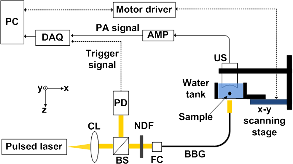 To investigate the potential of OF-OR-PAM, we have acquired depth-resolved PA B-scan images of a carbon fiber immerged in water. First, the carbon fiber was imaged within the focal zone of the Bessel-like beam [Fig. 3(a)]. As shown in Fig. 3(b), the cross-section of the carbon fiber is clearly visualized in the PA B-scan image. Figure 3(c) and 3(d) shows two one-dimensional profiles cut along the dotted lines 1 and 2, respectively. Although the diameter of the carbon fiber () is slightly thicker than the Bessel beam width (), we have estimated the lateral resolution based on the FWHM of the lateral profile, , well close to the diameter of the carbon fiber. The FWHM of the axial profile is , which is close to the axial resolution of the OF-OR-PAM system. Interestingly, we identified a mirror image of the fiber in the PA B-scan image [Fig. 3(b)], and the associated PA signal peak was visible in the axial profile [Fig. 3(d), indication with a solid arrow]. This mirror image was generated by the reflection of PA waves at the membrane which is the interface between water and air. Thus, it is confirmed that the distance between the fiber and membrane was estimated to . Then, the Bessel-beam generator moved down vertically along the direction until the sample was out of the optical focal zone [Fig. 3(c)], and we have acquired the PA B-scan image [Fig. 3(f)]. The quantified FWHM of the lateral profile was , which is broadened by the off-focus [Fig. 3(g)]. By contrast, despite the lower PA amplitude by times in the off-focus region compared to that in the on-focus, the FWHM of the axial profile was relatively maintained [Fig. 3(h)]. The reason is that the carbon fiber was still positioned within the ultrasonic focal zone () although it was out of the optical focal zone. In addition, we observed the ghost PA image along the x-direction, generated from the side lobes of the Bessel beam [Fig. 3(b) and 3(f)]. However, the measured PA signals from the ghost image was not significant, of that measured from the main lobe. The FWHMs of the lateral [Fig. 3(i)] and axial [Fig. 3(j)] profiles were quantified along the direction. Within the highest intensity region of the nondiffracting beam in the direction, the lateral resolution relatively remained, and then it rapidly deteriorated beyond the high intensity beam region. However, the axial resolution was fairly unchanged over the entire scanning range. Fig. 3Depth-resolved photoacoustic (PA) B-scan images of a carbon fiber with a diameter of 6.7 μm. (a) and (e): Diagram of the Bessel-beam positions in the water tank. The Bessel-beam overlaps with the carbon fiber in (a, ), but not in (e, ); (b) and (f): PA B-scan images acquired at the positions (a) and (e), respectively; (c) and (g): The lateral PA profiles cut along the lines 1 and 3, respectively; (d) and (h): The axial PA profiles cut along the lines 2 and 4, respectively; FWHMs of the (i) lateral and (j) axial profiles along the direction. The position is based on the position in Fig. 1(b). W, water; S, sample; M, membrane; BBG, Bessel-beam generator; and BB, Bessel beam.  To further investigate the feasibility of OF-OR-PAM, volumetric PA images were obtained by scanning the carbon fiber along two transverse directions ( and axes). Then, the data was processed through maximum amplitude projection (MAP). Figure 4(a) and 4(b) shows the PA MAP images of the carbon fiber acquired inside and outside the optical focal zone, respectively. The carbon fiber was clearly visualized in the PA MAP image [Fig. 4(a)] when it was on focus, and the PA image matches well with the inset photograph. The PA MAP image was clearly blurred in the off-focus region [Fig. 4(b)]. Fig. 4Photoacoustic (PA) maximum amplitude projection (MAP) images acquired at (a) and (b) . The microscopic photograph of the carbon fiber is shown in the inset in (a). 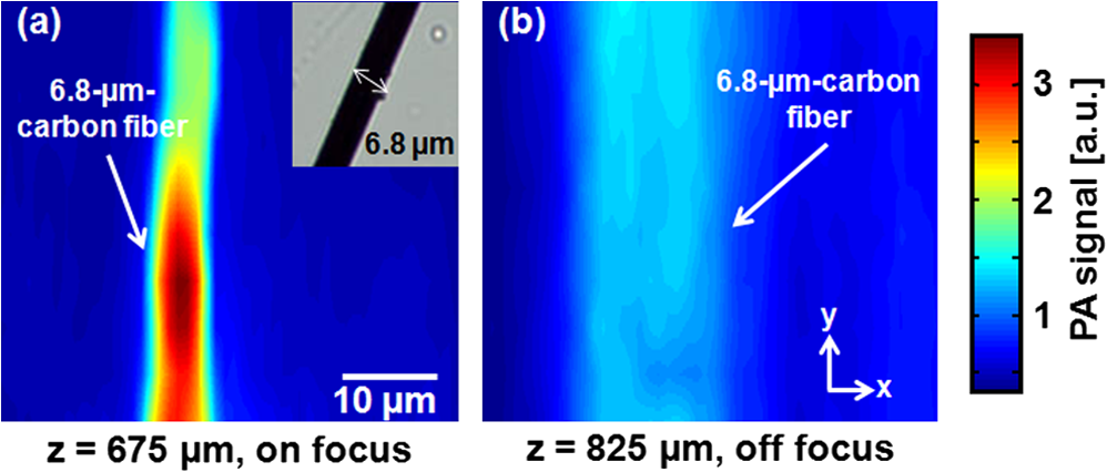 In conclusion, we present the first objective-free optical-resolution photoacoustic microscopy (OF-OR-PAM) using the all-fiber Bessel-beam generator in a transmission mode. By successfully imaging a carbon fiber, we have proved the feasibility of OF-OR-PAM. Unlike conventional OR-PAM, no objective lens and its accompanying optics/mechanical parts are required to give an ample opportunity in the system integration for in vivo imaging. To further improve for in vivo PA imaging studies, two issues must be resolved: (1) development of a reflection mode system and (2) improvement on the working distance, less than in the current system. Potentially, OF-OR-PAM will be extremely useful to develop a compact handheld OR-PAM or PA endoscopy system. AcknowledgmentsThis research was supported by the University at Buffalo Research Foundation faculty start-up fund, the Pilot Studies program of the University at Buffalo Clinical and Translational Research Center and the Buffalo Translational Consortium to C. K., supported by the Brain Korea 21 Project, the Korea NRF, and the Korea MEST-2011-00181613 to K.O., and supported by Ministry of Health & Welfare through the Korea Healthcare technology R&D Project A102024-1011-0000200, the Korea NRF, and the Korea MEST -2012-0005047 to J. K. ReferencesC. KimC. FavazzaL. V. Wang,
“In vivo photoacoustic tomography of chemicals: high-resolution functional and molecular optical imaging at new depths,”
Chem. Rev., 110
(5), 2756
–2782
(2010). http://dx.doi.org/10.1021/cr900266s CHREAY 0009-2665 Google Scholar
H. F. Zhanget al.,
“Functional photoacoustic microscopy for high-resolution and noninvasive in vivo imaging,”
Nat. Biotechnol., 24
(7), 848
–851
(2006). http://dx.doi.org/10.1038/nbt1220 NABIF9 1087-0156 Google Scholar
L. V. Wang,
“Multiscale photoacoustic microscopy and computed tomography,”
Nat. Photon., 3
(9), 503
–509
(2009). http://dx.doi.org/10.1038/nphoton.2009.157 1749-4885 Google Scholar
L. V. WangS. Hu,
“Photoacoustic tomography: In vivo imaging from organelles to organs,”
Science, 335
(6075), 1458
–1462
(2012). http://dx.doi.org/10.1126/science.1216210 SCIEAS 0036-8075 Google Scholar
C. Kimet al.,
“In vivo molecular photoacoustic tomography of melanomas targeted by bioconjugated gold nanocages,”
ACS Nano, 4
(8), 4559
–4564
(2010). http://dx.doi.org/10.1021/nn100736c 1936-0851 Google Scholar
Z. Xieet al.,
“Laser-scanning optical-resolution photoacoustic microscopy,”
Opt. Lett., 34
(12), 1771
–1773
(2009). http://dx.doi.org/10.1364/OL.34.001771 OPLEDP 0146-9592 Google Scholar
J. Yaoet al.,
“Label-free oxygen-metabolic photoacoustic microscopy in vivo,”
J. Biomed. Opt., 16
(7), 076003
(2011). http://dx.doi.org/10.1117/1.3594786 JBOPFO 1083-3668 Google Scholar
K. Maslovet al.,
“Optical-resolution photoacoustic microscopy for in vivo imaging of single capillaries,”
Opt. Lett., 33
(9), 929
–931
(2008). http://dx.doi.org/10.1364/OL.33.000929 OPLEDP 0146-9592 Google Scholar
J. Lauferet al.,
“In vivo preclinical photoacoustic imaging of tumor vasculature development and therapy,”
J. Biomed. Opt., 17
(5), 056016
(2012). http://dx.doi.org/10.1117/1.JBO.17.5.056016 JBOPFO 1083-3668 Google Scholar
C. ZhangK. MaslovL. V. Wang,
“Subwavelength-resolution label-free photoacoustic microscopy of optical absorption in vivo,”
Opt. Lett., 35
(19), 3195
–3197
(2010). http://dx.doi.org/10.1364/OL.35.003195 OPLEDP 0146-9592 Google Scholar
J. Kimet al.,
“Fourier optics along a hybrid optical fiber for Bessel-like beam generation and its applications in multiple-particle trapping,”
Opt. Lett., 37
(4), 623
–625
(2012). http://dx.doi.org/10.1364/OL.37.000623 OPLEDP 0146-9592 Google Scholar
S. R. Leeet al.,
“All-silica fiber Bessel-like beam generator and its applications in longitudinal optical trapping and transport of multiple dielectric particles,”
Opt. Express, 18
(24), 25299
–25305
(2010). http://dx.doi.org/10.1364/OE.18.025299 OPEXFF 1094-4087 Google Scholar
|


