|
|
1.IntroductionOptical tissue phantoms (OTPs) that simulate optically compatible tissue characteristics have been used for the evaluation of optical system performance,1 calibration of optical devices,1–3 and in vitro simulation of light distribution.2,3 Unlike other types of OTPs (gel or liquid), solid OTPs have been preferentially used because they have a long shelf life and can be easily produced.3–5 However, it is difficult to build thin-layer solid OTPs (TSOTPs) that are of comparable thickness to the human epidermis with several layers (four to five layers).6 Various methods have been developed to build OTPs with epidermal thickness.7–9 Bruin et al.10 and Saager et al.4 described the use of a customized frame to build OTPs with epidermal thickness, and Urso et al.7 reported that epidermal thickness was achieved by placing an OTP mixture between glass slides. Furthermore, Tseng et al.11 reported that epidermal thickness could be adjusted by calculating the solvent volume before the curing process, while Bergmann et al. reported that the thickness of an OTP could be controlled by adjusting the repetition rate of the spraying process.6 Although many materials and methods have been proposed for the construction of TSOTPs with epidermal thickness, there remains substantial inaccuracy and inconvenience among these procedures, and there has been no consensus on an appropriate and efficient procedure for the fabrication of TSOTPs.6 The present methods have several common limitations such as long production times, precipitation of chromophore particles, and microscopic particle clustering.4,7,10 Moreover, none of these studies have successfully achieved the epidermal thicknesses of .12 This study introduces a new spin-coating method (SCM) to fabricate reliable and reproducible TSOTPs with epidermal thickness. SCMs have been widely used in the microelectronics industry to fabricate thin and homogeneous films over large areas.13–19 In addition, it provides simple and quick process without any cumbersome processes. In this study, the SCM controls the TSOTP thickness as a function of the spin speed and number of layers. TSOTPs were fabricated to mimic the epidermis layer only considering the absorption property for which various concentrations of Indian ink were used. Finally, the TSOTPs were quantitatively evaluated to determine the absorption coefficients and the thickness. 2.Materials and MethodsFigure 1(a) shows the procedure used for the preparation of the OTP mixture. Figure 1(b) shows the procedure used to characterize the TSOTPs, which included the preparation of the OTP mixture, the spin coating process, thickness measurements of the TSOTPs, and measurements of their optical properties. Fig. 1(a) Procedure for preparation of the OTP mixture; (b) procedure for characterization of the TSOTP, which is composed of the OTP preparation, spin-coating process, thickness measurement of OTP, and optical property measurement. 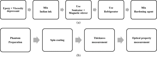 2.1.Preparation of Optical Tissue Phantom MixtureThe OTP mixture was composed of epoxy, viscosity depressant, and Indian ink. An epoxy (KE-300NS, KPS Inc., Gwangju, Republic of Korea) was used as a base material to fabricate the TSOTPs because it easily solidifies.18 A viscosity depressant (KE-300E, KPS Inc., Gwangju, Republic of Korea) was used to reduce the high viscosity of the epoxy that could affect the thickness and uniformity of the OTPs.18 The viscosity depressant and the epoxy were mixed at an ambient temperature of 18°C in a ratio using five different concentrations (0.2%, 0.4%, 0.6%, 0.8%, and 1.0% of total volume). Indian ink was used as an absorber to mimic melanin, which is a dominant optical property in epidermis.11 Indian ink provides a nearly uniform absorption spectrum over a wide spectral range and also maintains stable absorption properties over a long time period.1 The OTP mixture was mixed using a sonicator (Power Sonic505, Hwashin Co., Seoul, Republic of Korea) and magnetic stirrer for 20 min each to break down absorber particles and prevent aggregation. The OTP mixture was stored in a refrigerator for 1 h to minimize viscosity variation, which may occur at higher temperatures as a result of a heat reaction during the mixing process. Finally, a hardening agent (KH-700NS, KPS Inc., Gwangju, Republic of Korea) was mixed with the OTP mixture in a ratio. 2.2.Fabrication of Thin-Layer Optical Tissue Phantoms by a Spin-Coating MethodGlass slide substrates () were cleaned with piranha solution ( ratio of sulfuric acid and hydrogen peroxide) for approximately 1 to 1.5 h, rinsed with distilled water and acetone, and dried at an ambient temperature of 18°C. A 1 ml sample of the OTP mixture was poured onto the center of the glass slide, which was placed on a spin-coater (ACE-200, I-NEXUS Inc., Sungnam, Republic of Korea). The spin-coater was operated for 62 s (acceleration time of 2 s and spin time of 60 s) at seven different spin speeds of 250, 500, 750, 1000, 1500, 2000, and 2500 rpm. The spin time was set at 60 s because it has been previously established that spin times greater than 40 s do not affect thickness.13,14,16 After the spin-coating process, an incubator (WIG-32, DAIHAN Scientific Co. Ltd., Wonju, Republic of Korea) was used to vulcanize the TSOTPs for 4 h at 60°C. TSOTPs were fabricated as a function of the spin speed, absorber concentration, and number of layers. 2.3.Thickness Measurements of Thin-Layer Optical Tissue PhantomsA digital microscope (KH-7700, HIROX, Tokyo, Japan) was used to measure the thicknesses of the TSOTPs. Each glass slide with TSOTP was cut using a rolling diamond cutter, and the boundary between the TSOTP and the glass slide was imaged using a digital microscope. Five repeated measurements were performed at three different locations (two at the edges and one at the center) of each TSOTP sample to ensure high measurement accuracy. 2.4.Measurement of Optical Properties of Optical Tissue PhantomsFour one-layer TSOTPs with approximately 70 μm thickness were fabricated for each concentration of the absorber, and the absorption was measured at 660 nm using a spectrometer (USB4000, Ocean Optics, Florida) equipped with a double-integrating sphere and a tungsten-halogen lamp (HL 2000, Ocean Optics, Florida) as a light source. Three repeated measurements were performed at three randomly selected locations for each TSOTP sample. The absorption coefficients of each TSOTP were calculated by applying the inverse adding doubling (IAD) method using a scattering coefficient () and anisotropic factor () based on previous Refs. 20 and 21. 2.5.Fabrication Feasibility of a Double Layer Optical Tissue PhantomAs a preliminary study, three double-layer OTPs were fabricated to mimic the epidermal and dermal layers in tissue. Epidermal TSOTP (1.0% Indian ink of total volume) with approximately 80 μm thickness was first fabricated in a disposable Al Dish (D70-100, Disposable Al Dish, Seoul, Republic of Korea) using the SCM, as mentioned in 2.2. Then, dermal OTP (1.0% titanium dioxide of total volume) with 2.85 mm () thickness was fabricated on top of the epidermal TSOTP. The transport attenuation coefficient () of the double layer OTPs was measured at 660 nm by using the identical measurement system described in Sec. 2.4. Three repeated measurements were performed at three randomly selected locations for each double layer OTP sample. 3.ResultsThe top, center, and bottom frames in Fig. 2 show digital microscopic images of one-layer, two-layer, and three-layer TSOTPs, respectively, fabricated at 250 rpm [Fig. 2(a)], and 2500 rpm [Fig. 2(b)]. The layers of TSOTP were of homogeneous thickness in the region of interest (ROI), and their thickness increased as a function of the number of layers. The boundaries between the TSOTPs and the glass slides were clearly distinguished. The scratch on the cross-sectional TSOTP, as observed in the figure, might be caused in the cutting process of TSOTP when a rolling diamond cutter is used for the thickness measurement; this scratch does not affect the phantom thickness and homogeneity. Fig. 2Sample images of TSOTPs fabricated at spin speeds of (a) 250 rpm; (b) 2500 rpm; the top, center, and bottom images indicate one-layer, two-layer, and three-layer TSOTPs, respectively. 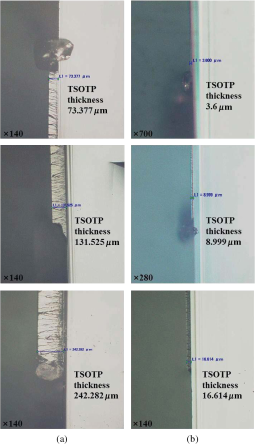 Figure 3 shows thickness variation as a function of the spin speed and absorber concentration. The TSOTP thickness decreased exponentially as a function of the spin speed and drastically decreased up to 750 rpm. One-layer TSOTPs reached a maximum thickness of at 250 rpm and a minimum thickness of at 2500 rpm. The five different concentrations of absorber did not affect the thicknesses of TSOTPs fabricated at the same spin speeds. Fig. 3Thickness variation of one-layer TSOTPs as a function of spin speeds from 250 to 2500 rpm at five different absorber concentrations. 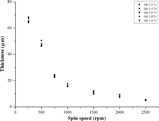 Figure 4 shows the thickness variations of multilayer TSOTPs as a function of the spin speed at the same absorber concentration (1.0% of total volume). The TSOTP thickness decreased exponentially as a function of the spin speed and increased as a function of the number of layers. Mathematical equations (Table 1) were obtained to predict TSOTP thickness as a function of the spin speed by performing a power function curve fitting (solid line in the figure) as follows: where indicates the variable of the spin speed and and are constants. The results indicated a significant correlation () between the TSOTP thickness and spin speed in all cases.Fig. 4Thickness variation of multilayer TSOTPs as a function of spin speeds. Power curve fitting shows correlation coefficients of for one layer, for two layers, for three layers.  Table 1Power curve fitting equations for thickness variation of TSOTPs as a function of spin speed.
Figure 5 shows that the absorption coefficient exponentially increased as a function of the absorber concentration. The following mathematical equation was extracted by performing a power function curve fitting: where and indicate the absorption coefficient and absorber concentration, respectively. The absorption coefficient showed a strong correlation with the absorber concentration () and a high reproducibility as indicated by the low error bars.Fig. 5Absorption coefficients () of TSOTPs measured at 660 nm as a function of absorber concentrations from 0.2% to 1.0%. 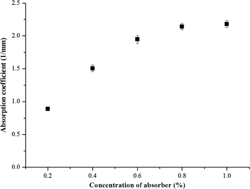 Figure 6(a) shows digital microscopic images of the dermal OTP (left image) and the double layer OTP (right image) that combines epidermal TSOTP and dermal OTP. The boundary between the epidermal TSOTP and dermal OTP was clearly distinguished in the double layer OTP (right image). Figure 6(b) shows the transport attenuation coefficients ( of three double-layer OTPs. Each double layer OTP presented the average of 4.78, 3.91, and and the uniform in the ROI, as indicated by low standard deviations. Fig. 6(a) Sample images of the dermal optical tissue phantom (OTP) (left image) and the double-layer OTP (right image), which has epidermal thin-layer solid OTP and dermal OTP; (b) transport attenuation coefficients () of double layer OTPs measured at 660 nm. The of the double-layer OTPs was 4.78, 3.91, and , respectively, thus having an average of . 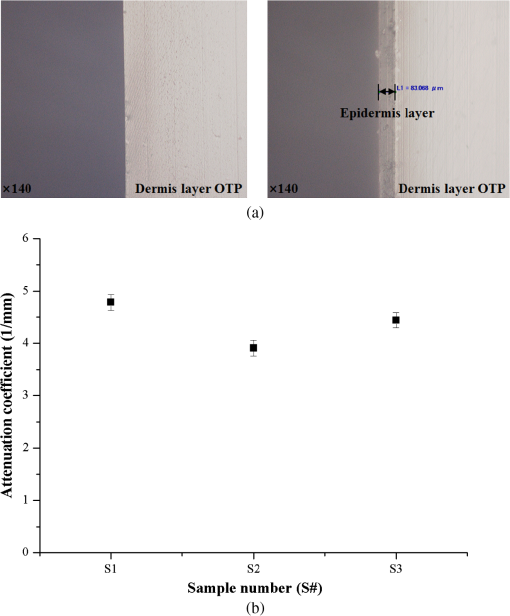 4.DiscussionAlthough conventional solid OTPs have been routinely used as essential tools in biomedical optics, the control of their thickness is difficult, requiring cumbersome and time-consuming production procedures. This study introduced a new SCM to partially address these problems, thus improve the fabrication efficacy of OTPs. When compared with conventional methods, the SCM can reduce fabrication time, easily control OTP thickness by managing the spin speed, and fabricate multilayer OTPs. The SCM can be used to easily fabricate OTPs of various thicknesses by managing the number of layers and the spin speed. In the conventional method, it is difficult and cumbersome to replicate the thickness of the stratum corneum () in the epidermal layer.22 However, the SCM was successfully used to fabricate TSOTPs with a minimum thickness of 5.1 μm and a maximum thickness of approximately 65 μm for a one-layer coating, which is comparable with the epidermal thickness (40 to 150 μm). The epidermis is composed of four to five layers depending on the skin region. By using the SCM, TSOTPs with epidermal thickness can be fabricated with one-layer or multilayer coating depending on the application. In future studies, the additional parameters of the SCM that may also affect thickness should be optimized with respect to the fabrication materials and procedures of OTP. The relationship between the spin speed and the thickness demonstrated that the thickness of the TSOTP may be affected by the centrifugal force associated with the rotary motion. A faster rotary motion generates greater centrifugal force, resulting in decreased thickness.13–17 Such a mechanism might affect the thickness of the TSOTP, which exponentially decreases as a function of the spin speed (Figs. 3 and 4). In the case of one-layer TSOTP, absorption coefficients increased as a function of absorber concentration (Fig. 5) but did not affect the thickness of the TSOTP (Fig. 3). It is known that the viscosity of base material is strongly related to the solvent of evaporation.13 This phenomenon results in a difference in thickness. In our case, there is no solvent evaporation process, owing to the properties of nonvolatile epoxy. Accordingly, the different absorber concentration may not directly affect the thickness of the TSOTP, as shown in Fig. 3. The thickness of the TSOTP might be affected by the viscosity of the OTP mixture. In a previous study,13 the film thickness was affected by the viscosity of the base solution. Based on that study, the thickness of the TSOTP was investigated for the viscosity of the OTP mixture. In the experiment, epoxy had a high viscosity and was not uniformly distributed on the glass slides during the spin coating process; therefore, a viscosity depressant was used to reduce the viscosity of the TSOTP. The viscosity of the OTP mixture was decreased significantly and therefore directly affected the uniformity of the OTP thickness. In future studies, it may be beneficial to investigate the effects of viscosity of the OTP mixture on the TSOTP thickness. As in the case of the one-layer TSOTPs, the thickness of the multilayer TSOTPs was exponentially decreased as a function of the spin speed and increased as a function of the number of layers at all spin speeds (Fig. 4). These results show that the SCM can fabricate TSOTPs of various thicknesses by manipulating the spin speed and the number of layers. In multilayer TSOTPs fabricated at the same concentration, it was difficult to identify the boundary between each TSOTP layer. This may arise from the use of the same absorption property, no air gap between layers, or the very low thickness of each layer. This study presented only three layers of TSOTP with the same absorption property to prove the feasibility of the SCM in the fabrication of the multilayer TSOTP. In future study, an epidermis layer with four to five layers will be fabricated with a different absorption property and thickness. Double-layer OTPs with the same absorption and scattering properties presented stable as indicated by the low standard deviations [Fig. 6(b)]. In performing IAD, tissue optical properties were identified using various approaches in the previous studies because the optical properties of human tissues vary depending on the anatomical locations, skin color, and optical agents; moreover, these properties are not yet established for all skin layers.20,21 This study first investigated the feasibility of the SCM in the fabrication of the epidermal TSOTP considering only absorption property and then double-layer OTP, which has epidermal TSOTP, and dermal OTP was fabricated by considering absorption and scattering properties. It should be noted that the results may vary depending on the fabrication material and procedure of the OTP. 5.ConclusionsThe SCM can be used to quantitatively fabricate one-layer and multilayer TSOTPs by controlling the spin speed to achieve epidermal thickness with absorption property. In addition, a double-layer OTP was fabricated by combining the dermal OTP onto the epidermal TSOTP fabricated using the SCM. In future studies, the epidermal TSOTP will be fabricated with skin texture (wrinkles) and with multiple layers having different absorption properties. The method of fabricating double-layer OTP will be characterized in detail. AcknowledgmentsThis research was supported by Leading Foreign Research Institute Recruitment Program (2010-00757) and Basic Science Research Program (2010-0016644) through the National Research Foundation of Korea (NRF) funded by the Ministry of Education, Science and Technology (MEST). ReferencesB. W. PogueM. S. Patterson,
“Review of tissue simulating phantoms for optical spectroscopy, imaging and dosimetry,”
J. Biomed. Opt., 11
(4), 041102
(2006). http://dx.doi.org/10.1117/1.2335429 JBOPFO 1083-3668 Google Scholar
T. MoffittY. C. ChenS. A. Prahl,
“Preparation and characterization of polyurethane optical phantoms,”
J. Biomed. Opt., 11
(4), 041103
(2006). http://dx.doi.org/10.1117/1.2240972 JBOPFO 1083-3668 Google Scholar
V. V. Tuchin, Handbook of Optical Biomedical Diagnostics, 311
–314 SPIE Press, Bellingham, WA
(2002). Google Scholar
R. B. Saageret al.,
“Multilayer silicone phantoms for the evaluation of quantitative optical techniques in skin imaging,”
Proc. SPIE, 7567 756706
(2010). http://dx.doi.org/10.1117/12.842249 PSISDG 0277-786X Google Scholar
M. L. Vernonet al.,
“Fabrication and characterization of a solid polyurethane phantom for optical imaging through scattering media,”
Appl. Optics, 38
(19), 4247
–4251
(1999). http://dx.doi.org/10.1364/AO.38.004247 APOPAI 0003-6935 Google Scholar
T. Bergmannet al.,
“Development of a skin phantom of the epidermis and evaluation by using fluorescence techniques,”
Proc. SPIE, 7906 79060T
(2011). http://dx.doi.org/10.1117/12.874676 PSISDG 0277-786X Google Scholar
P. Ursoet al.,
“Skin and cutaneous melanocytic lesion simulation in biomedical optics with multilayered phantoms,”
Phys. Med. Biol., 52
(10), N229
–239
(2007). http://dx.doi.org/10.1088/0031-9155/52/10/N02 PHMBA7 0031-9155 Google Scholar
T. L. TroyS. N. Thennadil,
“Optical properties of human skin in the near infrared wavelength range of 1000 to 2200 nm,”
J. Biomed. Opt., 6
(2), 167
–176
(2001). http://dx.doi.org/10.1117/1.1344191 JBOPFO 1083-3668 Google Scholar
G. Becket al.,
“Design and characterisation of a tissue phantom system for optical diagnostics,”
Lasers. Med. Sci., 13
(3), 160
–171
(1998). http://dx.doi.org/10.1007/s101030050070 LMSCEZ 1435-604X Google Scholar
D. M. de Bruinet al.,
“Optical phantoms of varying geometry based on thin building blocks with controlled optical properties,”
J. Biomed. Opt., 15
(2), 025001
(2010). http://dx.doi.org/10.1117/1.3369003 JBOPFO 1083-3668 Google Scholar
S. H. TsengA. GrantA. J. Durkin,
“In vivo determination of skin near-infrared optical properties using diffuse optical spectroscopy,”
J. Biomed. Opt., 13
(1), 014016
(2008). http://dx.doi.org/10.1117/1.2829772 JBOPFO 1083-3668 Google Scholar
J. Sandby-MollerT. PoulsenH. C. Wulf,
“Epidermal thickness at different body sites: relationship to age, gender, pigmentation, blood content, skin type and smoking habits,”
Acta. Derm. Venereol., 83
(6), 410
–413
(2003). http://dx.doi.org/10.1080/00015550310015419 0001-5555 Google Scholar
P. YimsiriM. R. Mackley,
“Spin and dip coating of light-emitting polymer solutions: matching experiment with modelling,”
Chem. Eng. Sci., 61
(11), 3496
–3505
(2006). http://dx.doi.org/10.1016/j.ces.2005.12.018 CESCAC 0009-2509 Google Scholar
P. L. G. JardimA. F. MichelsF. Horowitz,
“Optical monitoring for power law fluids during spin coating,”
Opt. Express, 20
(3), 3166
–3175
(2012). http://dx.doi.org/10.1364/OE.20.003166 OPEXFF 1094-4087 Google Scholar
V. CreganS. B. O'Brien,
“A note on spin-coating with small evaporation,”
J. Colloid Interface Sci., 314
(1), 324
–328
(2007). http://dx.doi.org/10.1016/j.jcis.2007.05.019 JCISA5 0021-9797 Google Scholar
A. G. EmslieF. T. BonnerL. G. Peck,
“Flow of a viscous liquid on a rotating disk,”
J. Appl. Phys., 29
(5), 858
–862
(1958). http://dx.doi.org/10.1063/1.1723300 JAPIAU 0021-8979 Google Scholar
F. C. Krebs,
“Fabrication and processing of polymer solar cells: A review of printing and coating techniques,”
Sol. Energy Mater. Sol. Cells, 93
(4), 394
–412
(2009). http://dx.doi.org/10.1016/j.solmat.2008.10.004 SEMCEQ 0927-0248 Google Scholar
Q. F. Zhouet al.,
“Alumina/epoxy nanocomposite matching layers for high-frequency ultrasound transducer application,”
IEEE Trans. Ultrason. Ferroelectr. Freq. Control, 56
(1), 213
–219
(2009). http://dx.doi.org/10.1109/TUFFC.2009.1021 ITUCER 0885-3010 Google Scholar
G. Pompeo,
“AFM characterization of solid-supported lipid multilayers prepared by spin-coating,”
Biochim. Biophys. Acta, 1712
(1), 29
–36
(2005). http://dx.doi.org/10.1016/j.bbamem.2005.03.007 BBACAQ 0006-3002 Google Scholar
W. F. CheongS. A. PrahlA. J. Welch,
“A review of the optical properties of biological tissues,”
IEEE J. Quantum Electron., 26
(12), 2166
–2185
(1990). http://dx.doi.org/10.1109/3.64354 IEJQA7 0018-9197 Google Scholar
V. Tuchinet al.,
“Finger tissue model and blood perfused skin tissue phantom,”
Proc. SPIE, 7898 78980Z
(2011). http://dx.doi.org/10.1117/12.881604 PSISDG 0277-786X Google Scholar
P. Ovaereet al.,
“The emerging roles of serine protease cascades in the epidermis,”
Trends Biochem. Sci., 34
(9), 453
–463
(2009). http://dx.doi.org/10.1016/j.tibs.2009.08.001 TBSCDB 0167-7640 Google Scholar
|

