
|
|
|
Photoacoustic microscopy (PAM) is a mode of photoacoustic tomography (PAT), which offers high sensitivity to optical contrast in biological tissues.1 Optical-resolution PAM (OR-PAM) is implemented by focusing the illumination through an objective lens; thus OR-PAM can achieve optical diffraction limited lateral resolution with maximum imaging depths up to one transport mean-free path ( in tissue).2,3 OR-PAM can provide structural imaging, and metabolic imaging.4,5 Various kinds of OR-PAM have also been explored to meet specific requirements, such as high speed,6 high resolution,7,8 deep imaging depth,3 and handheld operation.9 For OR-PAM, high imaging speed is always desirable because it enables us to observe dynamic biological processes while mitigating motion artifacts. For most OR-PAM systems based on both a single optical focus and a single-element ultrasonic transducer in confocal configuration, mechanical raster scanning along two lateral directions provides limited volumetric imaging speeds. Although optical scanning (i.e., scanning using galvo mirrors) can improve the speed greatly, it is usually used with an unfocused or a single-axis focused ultrasonic transducer, which results in a limited field of view (FOV) or compromised signal to noise ratio (SNR). Moreover, the volumetric imaging speed for OR-PAM with either mechanical or optical scanning is eventually limited by the laser pulse repetition rate (PRR). Thus to achieve high imaging speed, lasers with high PRR (, or even faster) are employed.6,9 Currently, lasers with such high PRR usually lack the wavelength tunability, which is essential for imaging of some physiological functions, such as the oxygen saturation of hemoglobin (). Moreover, high PRR translates to high average optical power, which may produce excessive tissue heating. Our lab previously reported a multifocal OR-PAM (MFOR-PAM) with times faster imaging speed (without considering the multiplexing effect) than a single-focus OR-PAM,10 so it relieves the demand for a high laser PRR. Besides the imaging speed improvement, the measurement capability makes MFOR-PAM potentially promising in clinical and preclinical applications. However, the original MFOR-PAM works in transmission mode, only suited for imaging thin biological samples. Therefore, it is necessary to develop reflection-mode MFOR-PAM. We implemented the reflection-mode MFOR-PAM by placing a microlens array directly below the ultrasonic array transducer, with both immersed in water, as shown in Fig. 1. To get one-dimensional (1-D) multifocal optical illumination, the microlens array (250 μm pitch and 1.2 mm focal length in air, 11-1640-123-000, SUSS MicroOptics, Switzerland) was precisely cut by Biomedical-Optics LLC to 0.5 mm wide and 10 mm long. Due to the limited detection range of the ultrasonic array transducer, only 20 microlenses were used to provide 20 focused optical illumination spots along the lateral axis. At a laser wavelength of 570 nm, Zemax (Radiant Zemax LLC) simulation shows that the water-immersed microlens can produce a diffraction-limited focus with a radius of at the waist and an effective focal length of 3.4 mm. The centers of the microlens array and the ultrasonic array transducer were aligned in both the elevational ( axis in Fig. 1) and lateral ( axis in Fig. 1) directions. The microlens array was carefully adjusted so that the optical foci of the microlens array and the cylindrical focus of ultrasonic array transducer overlap. To reflect the laser beam, which is incident from the elevational side, a customized microprism (, Biomedical-Optics LLC) was used. The microprism and the microlens array were aligned on their centers and glued together with optically transparent adhesive. The ultrasonic array transducer consisted of 48 elements with 100 μm pitch, and each element () had a central frequency of 30 MHz and a 70% receiving-only bandwidth. A tunable dye laser (Cobra, Sirah, Germany) pumped by a Q-switched Nd:YLF laser (INNOSLAB, EdgeWave, Germany) provided photoacoustic excitation at 1.35 kHz. Technical details about the ultrasound array system can be found in our previous publications.10,11 Fig. 1Configuration of the reflection-mode MFOR-PAM system. (a) Schematic of the whole system. ND, neutral density filter; BS, beam sampler; PD, photodiode; CL, convex cylindrical lens; M, mirror; UAT, ultrasonic array transducer; CAL, cylindrical acoustic lens; MLA, microlens array; VGA, variable gain amplifier. (b) 3-D view of the components in the dashed box of (a). To show the configuration more clearly, only one side of the PA wave is presented. (c) Dimensions used to estimate the PA wave receiving percentage of the ultrasonic array transducer. and , focal length and width of the microlens array immersed in water; , focal length of the cylindrical acoustic lens; , width of the transducer element; , portion of the width that cannot receive PA waves. 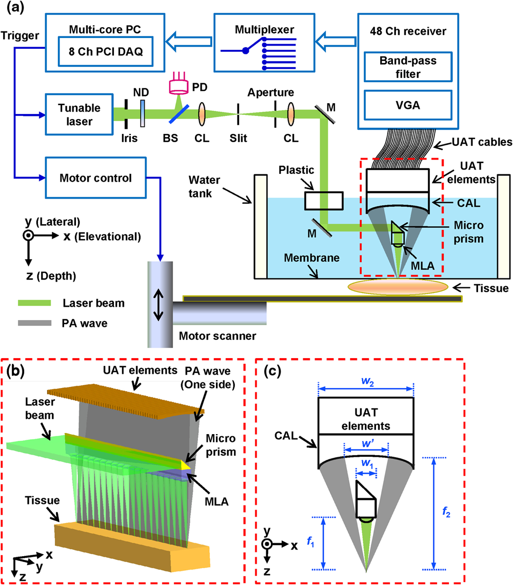 In this reflection-mode MFOR-PAM, the PA wave was partially reflected by the microlens array when propagating to the transducer. Figure 1(c) shows the dimensions that were used to estimate the fractional PA wave loss, which is . Here we neglect the acoustic diffraction effect because the acoustic wavelength is much smaller than the width of the microlens array. With , , , and , the fraction of acoustic energy reaching the transducer array, was , equal to . Also, this design allows us to extend the microscope’s working distance to the whole optical focal length, which is convenient in biomedical imaging applications. In MFOR-PAM, the lateral resolution and elevational resolution are the same because of the symmetric property of the optical focus.10 Therefore, hereafter we use “lateral resolution” to denote both the lateral resolution and elevational resolution. To quantify the lateral resolution of the reflection-mode MFOR-PAM, we imaged two crossed 6-μm-diameter carbon fibers, using a scanning step size of 2 μm. Figure 2(a) shows the maximum amplitude projection (MAP) along the depth direction for the carbon fibers. Figure 2(b) shows the PA signal amplitude along the dashed line in (a). The full width at half maximum (FWHM) of the curve in Fig. 2(b) measures 16 μm, which represents the lateral resolution of the system. Due to the water immersion, this value is lower than the 10 μm lateral resolution of the transmission mode MFOR-PAM. Although there is loss of the PA wave compared with the transmission mode MFOR-PAM, the signal to noise ratio (SNR) in Fig. 2(a) still reaches 19 dB, which is adequate for imaging micro blood vessels. The axial resolution, which is determined by the receiving ultrasonic bandwidth of the transducer, is , as reported in previous publications.10,11 The penetration depth of the reflection-mode MFOR-PAM was also studied by imaging a 250 μm-diameter black needle obliquely inserted into the leg of a nude mouse (Hsd, Athymic Nude-Foxnlnu, Harlan Co.). With time gain compensation, Fig. 2(c) shows that the black needle can still be observed 0.7 mm beneath the skin surface of the mouse leg. Compared to the maximum imaging depths of other OR-PAM systems (up to 1.2 mm),2,6 this depth is shallower because the microlens array reflects of the PA wave. However, this maximum imaging depth is still sufficient for observations of many shallow structures. Fig. 2Characteristics of the reflection-mode MFOR-PAM. (a) MAP image of two crossed 6-μm-diameter carbon fibers. (b) PA amplitude distribution along the dashed line in (a). Blue circles are the experimental data, and the red curve is the Gaussian fit. (c) In vivo photoacoustic image of a black needle inserted obliquely into the leg of a nude mouse.  Figure 3(a) shows an in vivo MAP image of a mouse ear microvasculature acquired by the reflection-mode MFOR-PAM system. The MAP image was processed by the Gaussian low pass filter. The laser wavelength was set to the isosbestic wavelength of 570 nm, where hemoglobin has high absorption. Figure 3(b) shows a snapshot from the 3-D animation (Video 1). Microvessels were clearly imaged in both the MAP image and the 3-D animation. The imaging time to acquire the data set of Fig. 3 () was . The incident laser energy on each microlens was limited to , and the laser fluence on the ear surface was estimated to be , lower than the ANSI limit . Fig. 3In vivo photoacoustic images of a nude mouse ear. (a) MAP image. (b) Snapshot from the 3-D animation, showing the microvasculature in (a). (Video 1, MPEG, 4 MB) [URL: http://dx.doi.org/10.1117/1.JBO.18.3.030501.1]. 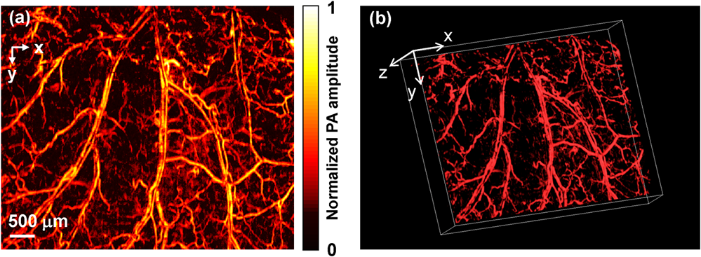 With the flexibility of reflection mode, the in vivo PA image of a nude mouse brain was also acquired. Figure 4(a) shows the MAP image of a living adult mouse brain. The MAP image was processed by the Gaussian low pass filter. The skin of the mouse brain was removed, but the skull was kept intact, as shown in Fig. 4(b). From Fig. 4(a), the microvessels can be clearly observed, even though the intact skull attenuated both the incident light and the PA wave. Figure 4(c) is a snapshot from the 3-D animation, showing the mouse brain from various viewing angles (Video 2). The 3-D animation shows the curved shape of the mouse brain. Fig. 4In vivo trans-cranial photoacoustic images of a nude mouse brain with the skin removed. (a) MAP image of the brain. (b) Photograph of the mouse brain with skin removed. The dashed box is the imaging area presented in (a). (c) Snapshot from the 3-D animation showing the structure in (a). (Video 2, MPEG, 4 MB) [URL: http://dx.doi.org/10.1117/1.JBO.18.3.030501.2].  In summary, we have developed a reflection-mode MFOR-PAM system using a microlens array and a linear ultrasonic array transducer. The reflection-mode MFOR-PAM was capable of acquiring volumetric PA images in vivo, with a lateral FWHM resolution of 16 μm, axial resolution of , and in vivo penetration depth up to 0.7 mm. Due to the combination of multiple optical foci and the ultrasonic array transducer, the lateral scanning range was reduced to only one pitch of the microlens array; thus the imaging speed was much faster than single-focus OR-PAM with mechanical scanning. Potentially the imaging speed can be further improved by eliminating the multiplexer, and using a higher PRR laser. Optical scanning within one pitch in the lateral direction can further improve the imaging speed by several times. A more densely packed microlens array with a smaller pitch might improve the imaging speed, but this usually means a shorter working distance if we want to maintain the NA or lateral resolution. Other multifocal designs might be developed to provide both a high NA and long working distance. AcknowledgmentsThis work was sponsored in part by National Institutes of Health (NIH) Grants R01 EB000712, R01 EB008085, R01 CA134539, U54 CA136398, R01 CA157277, R01 CA159959, and DP1 EB016986 (NIH Director’s Pioneer Award). L. V. Wang has a financial interest in Microphotoacoustics Inc., and Endra Inc., which, however, did not support this work. K. I. Maslov has a financial interest in Microphotoacoustics Inc., which did not support this work. The authors appreciate James Ballard’s close reading of the manuscript. They also thank Liang Song, Lidai Wang, Junjie Yao, and Jun Xia for helpful discussions and experimental assistance. ReferencesL. V. Wang,
“Multiscale photoacoustic microscopy and computed tomography,”
Nat. Photon., 3
(9), 503
–509
(2009). http://dx.doi.org/10.1038/nphoton.2009.157 1749-4885 Google Scholar
S. HuK. MaslovL. V. Wang,
“Second-generation optical-resolution photoacoustic microscopy with improved sensitivity and speed,”
Opt. Lett., 36
(7), 1134
–1136
(2011). http://dx.doi.org/10.1364/OL.36.001134 OPLEDP 0146-9592 Google Scholar
J. Yaoet al.,
“Double-illumination photoacoustic microscopy,”
Opt. Lett., 37
(4), 659
–661
(2012). http://dx.doi.org/10.1364/OL.37.000659 OPLEDP 0146-9592 Google Scholar
P. HajirezaW. ShiR. J. Zemp,
“Label-free in vivo fiber-based optical-resolution photoacoustic microscopy,”
Opt. Lett., 36
(20), 4107
–4109
(2011). http://dx.doi.org/10.1364/OL.36.004107 OPLEDP 0146-9592 Google Scholar
A. Krumholzet al.,
“Functional photoacoustic microscopy of diabetic vasculature,”
J. Biomed. Opt., 17
(6), 060502
(2012). http://dx.doi.org/10.1117/1.JBO.17.6.060502 JBOPFO 1083-3668 Google Scholar
J. Yaoet al.,
“Wide-field fast-scanning photoacoustic microscopy based on a water-immersible MEMS scanning mirror,”
J. Biomed. Opt., 17
(8), 080505
(2012). http://dx.doi.org/10.1117/1.JBO.17.8.080505 JBOPFO 1083-3668 Google Scholar
C. ZhangK. MaslovL. V. Wang,
“Subwavelength-resolution label-free photoacoustic microscopy of optical absorption in vivo,”
Opt. Lett., 35
(19), 3195
–3197
(2010). http://dx.doi.org/10.1364/OL.35.003195 OPLEDP 0146-9592 Google Scholar
C. Zhanget al.,
“Reflection-mode submicron-resolution in vivo photoacoustic microscopy,”
J. Biomed. Opt., 17
(2), 020501
(2012). http://dx.doi.org/10.1117/1.JBO.17.2.020501 JBOPFO 1083-3668 Google Scholar
P. HajirezaW. ShiR. J. Zemp,
“Real-time handheld optical-resolution photoacoustic microscopy,”
Opt. Express, 19
(21), 20097
–20102
(2011). http://dx.doi.org/10.1364/OE.19.020097 OPEXFF 1094-4087 Google Scholar
L. SongK. MaslovL. V. Wang,
“Multifocal optical-resolution photoacoustic microscopy in vivo,”
Opt. Lett., 36
(7), 1236
–1238
(2011). http://dx.doi.org/10.1364/OL.36.001236 OPLEDP 0146-9592 Google Scholar
R. J. Zempet al.,
“Realtime photoacoustic microscopy in vivo with a 30-MHz ultrasound array transducer,”
Opt. Express, 16
(11), 7915
–7928
(2008). http://dx.doi.org/10.1364/OE.16.007915 OPEXFF 1094-4087 Google Scholar
|


