
|
|
1.IntroductionHigh voltage nanosecond pulsed electric fields (nsPEFs) have been shown to be effective stimuli to induce apoptosis in cells, activate platelet aggregation, and as a skin cancer therapy.1–3 Theoretical models have also predicted that nsPEF could be used to manipulate neurological signals responsible for motor movement and pain.4,5 One experimental study performed by Pakhomov et al. has validated the potential for nsPEF to interfere with motor signals from the brain.6 Previous work exploring the impact of nsPEFs on cell plasma membranes has hypothesized that small nanometer-sized pores (nanopores) are preferentially formed. Nanopore formation, in contrast to the larger pores formed by longer pulses (electroporation), are less likely to pass large ions such as propidium, but freely allow passage of small ions.7,8 Various studies using diverse techniques such as electrophysiology,9–11 fluorescence microscopy,7,11 and direct ion measurement in bulk solution for longer pulse widths12 have supported the hypothesis that such “nanopores” exist. Interestingly, when exposed cells are under a whole cell patch clamp, nanopore activity appears to have unique electrical characteristics.13 These characteristics include inward rectification, slow opening and closing (as compared to ion channels), and demonstrate positive feedback at positive holding voltages.13 Of specific interest to this effort, creation of nanopores by nsPEF exposure causes changes in membrane potential (depolarization) by allowing movement of otherwise impermeable cations, such as sodium () and calcium (), across the plasma membrane. This induced depolarization fully recovers over several minutes.10 We believe that application of nsPEFs to neural tissue may provide a scalable technique for neuro-stimulation. Previous modeling work has shown that low intensity nsPEF exposures could potentially create the formation of an AP leading to acetylcholine release at the neuromuscular synaptic cleft, resulting in muscle contractions.4,5 Jiang and Cooper demonstrated that a single, 12 ns nsPEF at was capable of activating skin nociceptors.14 They were able to demonstrate this same effect at 100 pulses delivered at 4000 Hz with very low voltages ().14 Wang et al. showed contraction of rat cardiomyocyte using twenty pulses of 3 ns at .15 Nanosecond pulse exposure of neurosecretory chromaffin cells has also been shown to result in uptake and release of catecholamines.16 Importantly, by using specific voltage-gated channels (VGCC) antagonists, they revealed dependence of such influx on VGCC.17 This finding suggests that a more complex series of events could be responsible for nsPEF induced intracellular rises. Despite the lack of understanding of exact mechanisms of uptake after nsPEF exposure, it has been hypothesized that higher voltage nsPEF exposure will result in the formation of stable nanopores in the neuronal membrane causing sustained depolarization. Modeling work has suggested that at higher voltages ( at 10 ns or at 600 ns), nsPEFs can cause the inhibition of AP by forming a conductance block.4 Recent work by Nesin et al. has shown that a single 300 ns pulse exposure can inhibit both and channel activity.18,19 If proven effective, nsPEF delivery may provide researchers with a noncontact, nonchemical, and nondestructive technique to cause both stimulation and inhibition of neuronal activity. The goal of this paper is to determine the ED50 (point at which 50% of cells would be expected to show a 5% increase in fluorescence) for nsPEF-induced influx and membrane asymmetry in neural cells as a marker of nanoporation of the plasma membrane. This influx thereby sets an exposure basis for nsPEF-induced stimulation or down regulation of neuronal function. Development of such dose response relationships, between the delivered nsPEF intensity and observed biological effects, are critical to the development of a clear mechanistic understanding of the impact of such pulses on neurological activity. In this paper, we used confocal microscopy, in conjunction with specific fluorescence membrane dyes, to identify possible nanopore formation in rodent neuroblastoma (NG108) and mouse primary hippocampal neurons (PHN). Specifically, we used Annexin V to measure the externalization of phophatidylserine on the membrane surface, FM1-43 to monitor the changes in the membrane symmetry as used in previous studies with Jurkat and Myeloma cells, and Calcium Green AM-1 (CaGr) to track the movement of ions.20,21 2.Methods2.1.Cell CultureRodent neuroblastoma cells (NG108-15[108CC15]) were acquired from American Type Culture Collection (Cat# HB-12317, ATCC, Manassas, Virginia) and cultured according to the supplier’s protocol. Base medium consisted of Dulbecco’s Modified Eagles Medium without pyruvate (Cat# 11965-092, Invitrogen, Carlsbad, California) supplemented with 10% Fetal Bovine Serum (FBS) (30-2020 ATCC), 1% penicillin/streptomycin antibiotics (ATCC Cat# 30-2300), and HAT supplement (Cat #21060-017, Invitrogen) which contains 0.1 mM hypoxanthine, 400 nM aminopterin, and 0.016 mM thymidine. Cells were cultured at 37°C, 5% , and 95% humidity. Cell viability was checked regularly with the Invitrogen Countess Cell Counter (Eugene, Oregon). PHN were prepared from embryonic day 18 (E18) rat hippocampus. Tissues were acquired from a commercial vendor (Brainbits LLC, Springfield, Illinois). To promote growth and adhesion, glass bottom 35 mm culture dishes (Cat# P35GC-0-10-C, MatTek, Inc., Ashland, Massachusetts) were coated with concentration of poly-D-lysine (Sigma, St. Louis, Missouri) solution for approximately 24 hr at . Prior to use, the dishes were rinsed with sterile 18 MΩ deionized water and allowed to dry. In order to culture PHN, the hippocampus was dissociated by repeated triturating with a 1 mL pipette tip. Following a resting period, the supernatant, containing dispersed cells, was transferred to a 15 mL tube, centrifuged at for 1 min and removed. The remaining cell pellet was resuspended with 1 mL of NbActiv1™ (Cat# NbActiv1, Brainbits LLC, Illinois) with 25 μM glutamate (Sigma, Missouri). Cells were plated at approximately , and incubated at 37°C, 5% . After 4 days, half of the medium was exchanged with fresh, warm NbActiv4™ (Cat# NbActiv4, Brainbits LLC, Illinois) medium with 25 μM glutamate. This process was repeated every three to five days throughout the culture lifetime. 2.2.Fluorescence StainingA physiological buffer, referred to as “outside solution” was used as the primary staining and exposure buffer. Outside solution was comprised of 2 mM , 5 mM KCL, 10 mM HEPES, 10 mM Glucose, 2 mM , and 135 mM NaCl at 135 mM, and adjusted to a pH of 7.4 resulting in an osmolarity of 290 to 310 mOsm. To prepare cells for the staining procedure, the culture medium was removed, cells were washed with Dulbecco’s Phosphate-Buffered Saline twice, and 2 mL of outside solution was added. The staining protocol for each dye is outlined below:
Additionally, 4 mM Propidium iodide (Cat# 51-66211E, BD Biosciences, San Jose, California) was added in conjunction with each of these dyes prior to imaging to mark dead or injured cells, which were avoided. Following the loading of the fluorescent dye, the dish was placed onto an inverted microscope (710 LSM, Carl Zeiss MicroImaging GmbH, Germany). All experiments outlined in this paper were performed at room temperature, roughly 24°C to 26°C. 2.3.Exposure and ImagingExposure of single cells was accomplished under microscopy [Fig. 1(a)] using a custom micro-electric probe comprised of two 75-μm-diameter tungsten electrodes positioned in parallel with a gap spacing of approximately 150 μm [Fig. 1(b)]. The exposure configuration has been described in depth in previous publications9 [Fig. 1(c)]. In short, the electrodes were positioned within the field of view of the microscope using a manipulator mounted to the microscope stage (MPC-200, Sutter Inc. Novato California). nsPEFs were generated by a custom pulser system that utilizes a high voltage power supply to feed a transmission line circuit. Discrete pulse widths of 600, 400, 200, 60, 30, and 10 ns were delivered to the cells by this pulsing system at charging voltages up to 1 kV. A Stanford DG535 (Stanford Research Systems, Sunnyvale, California) digital delay generator was programmed to trigger the microscope, thus beginning image acquisition. After a preset delay, a second signal was sent to a HP 8112A pulse generator to trigger the firing of the nsPEF. An LSM-710, confocal microscope (Carl Zeiss MicroImaging GmbH, Germany) was programmed to acquire 1, image per second () for 30 s (90 total images 30 T-PMT, 30 FL1, and 30 FL2). In all experiments, the nsPEF exposure occurred after a 5-s delay to establish a baseline fluorescence level. To ensure accurate delivery of the pulse (amplitude and width), the nsPEF was monitored on a Tektronix TDS3052 500-MHz oscilloscope (Tektronix Inc, Beaverton, Oregon) for each exposure. Fig. 1(a) Diagram showing the position of the microelectrode in relation to the position of the cells. (b) An actual image of the electrodes’ position 50 μm above the cells. The probes are approximately 75 μm width and 150 μm apart. (c) Custom exposure system setup for the exposure of cells under confocal microscopy.  2.4.ModelingThe modeling and simulation method of finite difference time domain (FDTD) was used to calculate the electric field amplitude delivered to the cells. A 0.9% saline solution (permittivity 75.3, conductivity 1.55) and a pair of electrodes modeled as perfect conductors (75 μm diameter, 150 μm separation) placed 50 μm above the 180-μm-thick glass coverslip (permittivity 3.8, conductivity 0) at a 42 deg angle were used in the model calculations.22,23 A voxel size of was chosen with a time-step of 3.84e-15 s as required by Courant stability criteria. A long trapezoidal waveform consisted of a 0.5 ns duration linear ramp followed by a direct current (DC) component for the remainder of the simulation and was truncated once all field values reached a steady-state. The resulting field values should therefore be regarded as quasi-static, and represent the fields incident upon the cells during the DC portion of the nanosecond pulse. 2.5.Data AnalysisA numerical value for each channel was extrapolated from the virtual stack of images (cell bodies) for each frame using Image J software.24 The CaGr response was calculated as a percent change from the average of the three frames prior to exposure to the average of three frames taken 2 s after exposure (peak response) to avoid the deleterious effect of photobleaching. A representative temporal response of cells loaded with CaGr before and after nsPEF exposure is depicted in Fig. 2. For FM1-43, due to the more transient response of the dye, three baseline images were averaged, and the percent change was calculated against the average of the final 3 images (30 s post exposure). To quantify the electric field amplitude for each cell, a transparent 2-D image of the FDTD model described above was overlaid on each confocal image, and an approximate E-field was assigned to each cell based upon its position. Fig. 2(a) Time trace of fluorescence change of Calcium Green for a cell exposed to one 600 ns or one 60 ns pulse at and for a sham-exposed cell. (b) Image of the same cell 1 s before delivery of 600 ns pulse. All cells were viewed at and stained with Calcium Green. (c) Image of NG108 cell 5 s after being pulsed. The increase in green fluorescence is evident here, indicating an influx of .  The raw fluorescence data were processed into a binary dataset by setting a threshold at double the highest sham-exposed change observed (5% for CaGr and FM1-43). Probit analysis was used due to the inherent variability in fluorescence response of cells at or near the threshold exposure where both positive and negative responses can be seen. In direct analysis, this type of variability can lead to large population variation and inaccurate estimation of exposure thresholds. The binary data were fed into a Probit model and an estimated ED50 was calculated. 3.Results3.1.nsPEF-Induced UptakeUse of a pair of electrodes to expose cells plated onto a glass coverslip creates a very dynamic exposure dosimetry. Figure 3 illustrates the field profile that is projected onto the glass surface during nsPEF exposure. The “hotspot” is found between the electrodes, at a field strength of per 1 V applied, as predicted by the FDTD simulation. The pulsing system generates pulses at roughly a 500 V amplitude resulting in a peak field of . By analyzing all cells within the field of view, we arrive at a nearly linear relationship between fluorescence change due to calcium influx and exposure amplitude in both cell types. However, differences were seen between cells exposed within the peak region at a lower applied voltage versus cells exposed to the same electric field outside the peak region during a higher applied voltage exposure. This is likely due to a nonuniformity of the field at the periphery of the profile resulting in a gradient field across the cell. Due to these observed uniformity issues, we limited our data analysis to only cells found within the peak field region defined as 80% of the predicted peak field or . Fig. 3(a) Side view of the FDTD-predicted E-field distribution between the tungsten electrodes showing the energy deposition at and above the glass coverslip. (b) Top down model of E-field distribution at the glass surface showing the area of highest energy deposition in relation to the tungsten micro-electro probes. 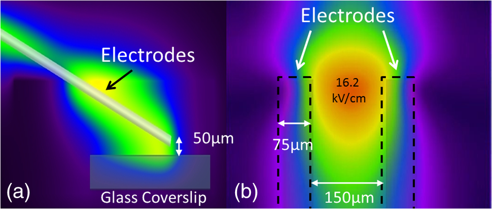 For detection of influx into each cell line, all available discrete pulse widths (600, 400, 200, 60, 30, and 10 ns) were tested. Cells exposed at the maximum charging voltage of the power supply, 999 V ( electric field at the cell), were compared to sham exposures. Figure 4 depicts the raw data for both PHN and NG108 upon exposure to the available pulse widths. As expected, shortening of the pulse reduces the observed increase in whole cell fluorescence indicative of uptake. Statistically significant () changes were observed at 60 ns and longer pulse widths for both cell types. To determine if nsPEFs caused any measureable intracellular release, was omitted from the outside solution and any residual was chelated by the addition of 2 mM K-EGTA. The gray circles show the results of nsPEFs in the absence of extracellular . This lack of a response does not rule out the possible release of intracellular from mitochondria or endoplasmic reticulum, but shows that such a release was not observed using our system. However, Beier et al., using high-speed imaging, recently reported that the influx of into a cell after nsPEF was due to both extra-cellular influx and intracellular release of .25 Fig. 4(a) Relative percent increase in the fluorescent levels of Calcium Green dye 5 s after a single pulse exposure at at varying pulse widths (Tau ramp) from 600 to 10 ns. (b) Probit analysis of Calcium Green Tau ramp for both PHN and NG108-15 with both upper and lower fiduciary limits and point at which 50% of cells would be expected to show a 5% increase in fluorescence. (c) Relative percent increase in the fluorescent levels of Calcium Green dye 5 s after a single pulse exposure at 600 ns at varying amplitudes (electric field ramp). (d) Probit analysis of Calcium Green electric field ramp for both PHN and NG108-15 with both upper and lower fiduciary limits and point at which 50% of cells would be expected to show a 5% increase in fluorescence. Error bars represent of the mean fluorescence change of 10 to 20 cells.  Using 5% increase as a threshold value (twice the variation seen in the sham population), the data were transformed into a binary dataset with cells that responded assigned a value of 1, and those not responding assigned a value of 0. Using Probit analysis, prediction curves were generated along with fiducial limits that correspond to 95% confidence intervals. Because of inherent variability between cells (morphology, stage of the cell cycle, position relative to the electrodes, and proximity of neighbors), not all cells responded to the insult. Probit analysis is optimal for dealing with this variability as it predicts the ED50 point based on binary data. By applying this statistical technique, we found that both NG108 and PHN display an ED50 at roughly 95 ns. This result suggests that the two cell lines have very similar responses, as is expected given their similar physiology despite obvious differences in their visible structure. This experiment was then repeated with the pulse width held to 600 ns, but with varying pulse amplitude (500, 250, 125, 62, 31, and 0 V applied). Using the FDTD model to predict the field intensity (Fig. 3), the data are shown as fluorescence change versus electric field (). Again, both cell types respond similarly with statistically significant () responses at or slightly above . Probit analysis determined the ED50 to be for NG108 and for PHN. Given the range of exposure amplitudes applied to the cells, the difference is not compelling, but does suggest that PHN may be slightly more sensitive (respond to nsPEFs at a lower voltage) than NG108. This difference could be related to cellular morphology, or maturity (primary versus blastoma) of the neuronal cells. Interestingly, previous work in GH3 and CHO cells using whole cell patch clamp found that changes in membrane permeability were first witnessed at around for 600 ns exposure durations, matching our predictions.10 Such a correspondence between the two techniques is rather impressive as whole cell patch clamp requires direct coupling to the cell via patch pipette and likely dialysis of intracellular molecules. 3.2.nsPEF-Induced Changes in Membrane ConformationThe formation of nanopores in the plasma membrane of a living cell will likely cause changes to the arrangement of the phospholipids that comprise the membrane. Vernier et al. first showed that fluorescently-labeled AV binds to the outside of the plasma membrane of Jurkat cells shortly after exposure to nsPEFs.20 Vernier et al. hypothesized that PS was externalizing through semi-stable aqueous pores in the plasma membrane, allowing for passive lateral diffusion into the outer leaflet of the membrane. In order to demonstrate that membrane conformation changes were occurring in excitable cells, we performed a series of experiments to measure the externalization of PS using FITC-AV. Figure 5 shows a PHN before exposure [Fig. 5(a)] and 10 s after exposure [Fig. 5(b)] to a single 600 ns nsPEF at . These images demonstrate an interesting occurrence that was seen in both NG108 and PHN; there appears to be a general lack of an isolated response on the side of the cell nearest the stimulating electrode. This appearance is in stark contrast to CHO-K1 cells which almost universally show expression of AV to originate at both the anode and cathode sides. Interestingly, even thin neuronal processes (axons and dendrites), which would be almost invisible to the field due to their size, were positive for AV binding. The reason for this whole cell response is yet unknown, but could be due to initiation of exocytosis, a common occurrence in excitable cells or activation of second messenger pathways due to influx. Figure 5(c) shows a graph depicting the single pulse response of PHN to 600, 200, and 60 ns pulses. Unfortunately, PHN cultures, as well as NG108, had a rather high FITC-AV background that prohibited a complete study of the dose response. Efforts were made to quench this background response by adding unlabeled AV prior to the experiment to bind to already externalized PS residues, but this proved unsuccessful. Fig. 5(a) Primary hippocampal neuron stained with Fluorescein-labeled Annexin V. Notice the high background. (b) Same PHN 10 s after a single 600 ns pulse, exposure. (c) Truncated Tau ramp showing a trend in which fluorescence increases as Tau increases. Error bars represent of the mean fluorescence change of 10 to 20 cells.  Due to the highly fluorescent background of FITC-AV in these cell lines, we substituted the more general plasma membrane dye FM1-43, which has been shown to report changes in membrane conformation in response to nsPEF stimulation in a similar fashion, albeit not specifically tracking the externalization of PS.26 FM1-43 is a fluorescent molecule that becomes more quantum efficient when it binds to lipid membranes, producing an increase in fluorescence intensity. This dye is typically used to observe exocytosis and endocytosis within neurons as a metric for membrane trafficking.27 In Fig. 6, a single neuron was imaged for 5 s, and then exposed to a single 600 ns nsPEF at . At 10 s, the center (red circle) was photobleached using a 488 nm argon laser source, effectively decreasing expression to the noise floor. New dye then incorporated into the plasma membrane and the fluorescence signal recovered over 60 s. The blue box represents a portion of the neuron that was outside the bleach region and depicts the typical response of the cell to nsPEFs. These data show that the plasma membrane conformation of neurons is highly responsive to nsPEFs, and that change is gradual over a minute post exposure. Using a photobleaching technique, we show that the dye incorporating into the membrane is not prebound to the membrane before exposure, but is new dye that was previously located in the extra-cellular buffer solution. Because the cells were allowed to reach equilibrium prior to exposure by resting in the dye for 15 min (causing natural incorporation of the dye into the plasma membrane as seen in the top image), we believe that this recovery of dye after photobleaching shows continuous changes in the plasma membrane over this 1-min period. This idea correlates well with previous approximations of the lifetime of nanopore activity being on the order of minutes. However, due to the lack of specificity, it is unclear what may be responsible for this ongoing change in membrane conformation. Coupled with AV results, these data suggest that nsPEFs are stimulating a lasting response from the plasma membrane that causes ion imbalance and possible attenuation of neuronal function. Fig. 6A single neuron was imaged for 5 s, and then exposed to a single 600 ns nsPEF at . At 10 s, the center (red circle) was photobleached using a 488 nm argon laser source, effectively knocking the expression to the noise floor. New dye then incorporated into the plasma membrane and the fluorescence signal recovered over 60 s. The blue box represents a portion of the neuron that was outside the bleach region and depicts the typical response of the cell to the nsPEF. 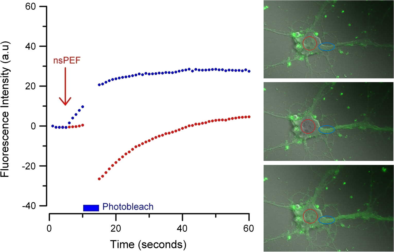 To capture the membrane response to different nsPEF widths using FM1-43 as an indicator of membrane change, six discrete pulse widths were tested and the resultant fluorescence change is reported versus the applied pulse width, as was performed with CaGr. These results are shown in Fig. 7. The applied voltage was 999 V, which gives a corresponding electric field prediction of . The fluorescence increase observed using FM1-43 is much more dramatic than CaGr with peak changes reaching 150% of the baseline fluorescence. However, like CaGr, this response was quite variable from cell to cell, especially at the lower pulse widths. Probit analysis of the raw data for FM1-43 predicted a pulse width ED50 of 103 ns. These data match well with the CaGr data generated within this same cell type (pulse width ED50 of 95 ns). This similarity suggests that observed changes in the membrane by FM1-43 occur at the same exposure intensity as uptake. This result further supports the claim that nanopores within the plasma membrane are created, allowing for both the uptake of extracellular ions and a disturbance in the conformation of the plasma membrane. However, we cannot exclude the possibility that the increase in FM1-43 fluorescence was due to channel-mediated uptake that triggered an exocytosis of intracellular vesicles such as lysosomes,27 or through direct uptake of the dye through nonselective ion channels.28 The time delay in response, less than a second and FM1-43 taking 60 s to maximize, would suggest that activation of such a mechanism is possible. Previous work has shown that longer electroporation pulses do indeed cause induced expression of LAMP1 protein, found exclusively in lysosomes, on the surface of the plasma membrane with increasing capacitance.29 The photobleaching experiment would suggest that if such exocytosis is occurring then “new” membrane (donated from lysosomes) is constantly being brought to the plasma membrane surface over the entire 60 s. Current efforts by our research group are focused on determining the degree to which lysosomal exocytosis following nsPEF exposure may be responsible for this observed change.30 Fig. 7(a) Relative percent increase in the fluorescence levels of FM1-43 dye 5 s after a single pulse exposure at at varying pulse widths from 600 to 10 ns. (b) Resultant prediction curve from Probit analysis and the corresponding predictions. Error bars represent of the mean fluorescence change of 10 to 20 cells.  It is unclear whether the observed burst is through nanopores or through direct nsPEF channel activation. Previous work has attempted to resolve this question by using a series of channel blocking agents on adrenal chromaffin cells and showed that L-type channels are activated by a burst into the cell due to membrane depolarization.17 Recent electrophysiological studies in NG108 and chromaffin cells showed that nsPEFs suppress activity of voltage-gated and channels.18,19 A follow-on publication showed that this suppression was independent of the influx of of ions, suggesting a direct effect of nsPEFs on the membrane or the or ion channels. To demonstrate that influx in our experiments was due to direct nanopore formation in the membrane, and not due to spontaneous action potential (AP) firing, we exposed PHN in the presence of tetrodotoxin (TTX). As with the drug-free CaGr results, a strong response was seen until the lowest pulse widths (Fig. 8). Using Probit analysis, the ED50 was predicted to be 67 ns, shorter than the prediction without TTX. However, despite using a similar number of cells, the fiducial limits were wider, resulting in substantial overlap between the confidence intervals of the CaGR, FM1-43, and CaGR-with-TTX datasets. These results agree with the data reported in adrenal chromaffin cells: specifically, that TTX addition does not impair the ability of nsPEFs to the cause uptake of extracellular ions. The generic calcium channel blocker was also used to complement the TTX data. Cells treated with displayed an ED50 of 85 ns. This observation suggests that activation of voltage-gated ion channels ( and ) and membrane depolarization is unlikely to be directly involved in the observed phenomena. Fig. 8(a) Raw data for PHN stained with Calcium Green, treated with TTX and exposed to Tau ramp (600, 400, 200, 60, 30, or 10 ns pulse). (b) Probit analysis for Tau ramp of FM1-43 stained PHN treated with TTX. (c) Raw data for PHN stained with Calcium Green, treated with cadmium chloride and exposed to Tau ramp (600, 400, 200, 60, 30, or 10 ns pulse). (d) Probit analysis for Tau ramp of FM1-43 stained PHN treated with cadmium chloride. (e) Comparison of point at which 50% of cells would be expected to show a 5% increase in fluorescence for Calcium Green, FM1-43, and Calcium Green treated with TTX or cadmium. Error bars represent of the mean fluorescence change of 10 to 20 cells. 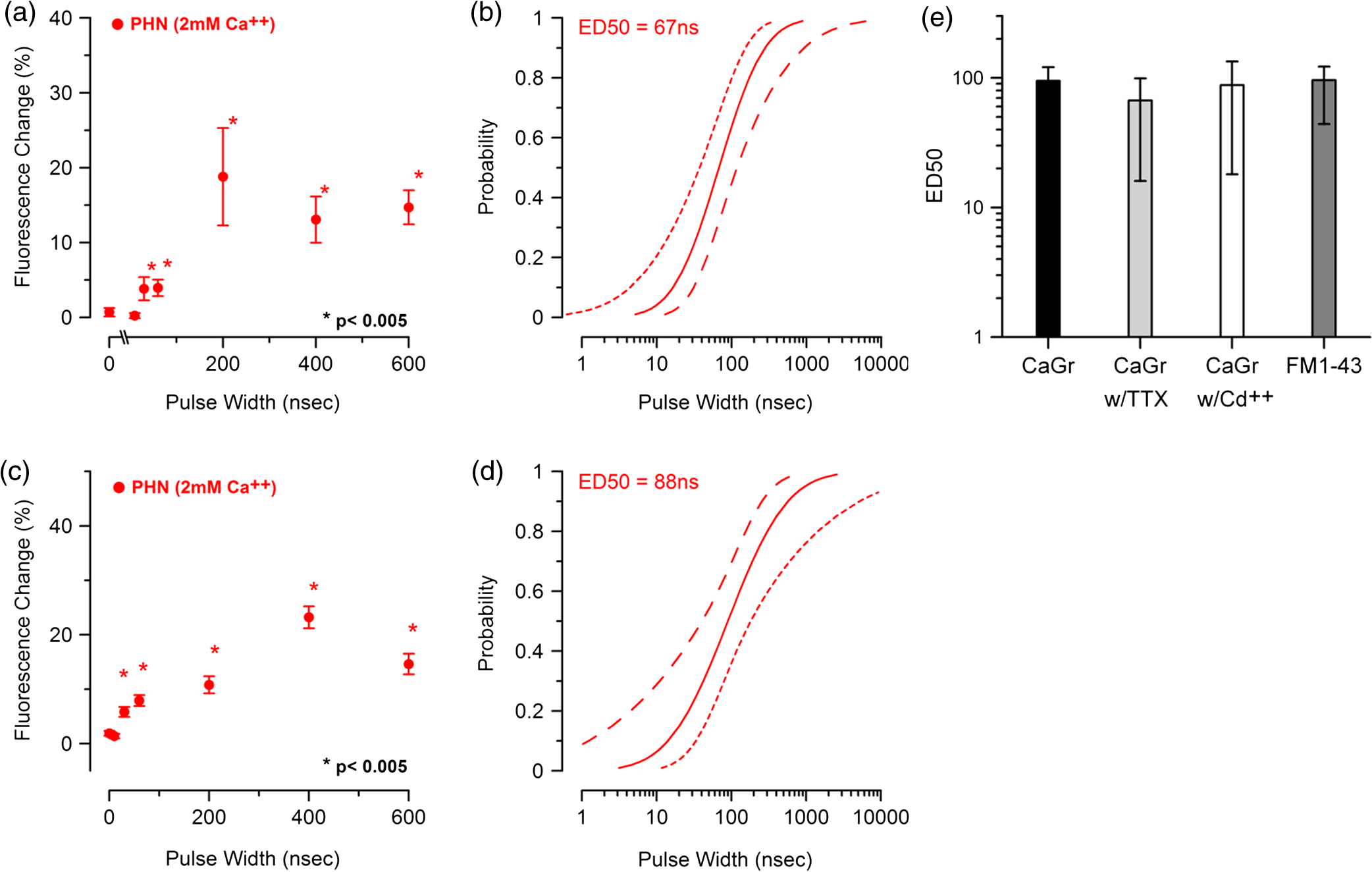 4.DiscussionThe overarching goal of this work was to establish the threshold for nanopore formation in both NG108 and PHN cells. It is known that mechanical, thermal, and/or chemical manipulation of the plasma membrane allows for ions to flow into the cell and begin a cascade of events that results in neurochemical release into the synaptic cleft. Previous work by our group and others has shown that nsPEFs can cause ion influx into a cell and that these same pulses disrupt the symmetry of the plasma membrane.7,10,11 We have observed that ions flood into the cytoplasm and remain elevated beyond 20 s post exposure. Experiments performed in the absence of extracellular showed no changes in intracellular , suggesting that the release of from intercellular stores is likely not responsible for the observed burst. By tracking membrane changes via FM1-43, we found that the ED50 for membrane change correlates well with the ED50 for uptake. This correlation may suggest that nanopore formation induced by nsPEFs causes both changes in the membrane and uptake of extracellular . Due to the diverse interactions of FM1-43 dye with various cellular functions, multiple explanations for this correlation remain plausible, including channel activation by nsPEFs. Blockage of voltage-gated channels by TTX did not alter the ED50 for uptake. Similarly, was used to block voltage gated , with no change in the ED50. These results suggest that membrane depolarization and voltage-gated channels are likely not involved in the nsPEF-induced influx. The prolonged uptake of extracellular observed in our experiments suggests that simple diffusion of into the cell through long-lived nanopores is unlikely the sole mechanism at play. This assertion is based on the fact that entry into a cell has been linked to a multitude of intracellular events such as contraction, secretion, synaptic transmission, gene expression, and initiation of cellular apoptosis. A substantial body of evidence has demonstrated a crucial role of intracellular in the up and down regulation of neuronal function. A change in the intracellular is a ubiquitous signaling mechanism that is frequently coupled with changes in neuronal membrane potential. To steer the future efforts, we postulate possible mechanism(s) responsible for the prolonged increase(s) of extracellular , and changes in membrane conformation. One such mechanism is through -induced release (CICR) reported in the myocytes31 and in neurons.32–36 In CICR inflow through VGCC triggers larger release of from sarcoplasmic reticulum by caffeine-sensitive ryanodine receptor activation. Another possible explanation/mechanism is that nsPEFs could initiate the hydrolysis of phospholipids of the neuronal membrane. The phosphoinositide phosphatidylinositol4,5-bisphosphate () on the internal layer of the plasma membrane plays a dramatic role as a regulator of ion transport proteins and as a source of second messenger compounds, including inositol trisphosphate (IP3).37 hydrolysis will increase intracellular through -sensitive stores in the endoplasmic reticulum of neuronal cells. released from neuronal intracellular stores through caffeine-sensitive ryanodine receptor38 and by (Ref. 39) will deplete such stores and will initiate the next (fourth) proposed mechanism: capacitive entry in neurons.40 Finally, we cannot exclude the possibility of release from direct poration or damage to cellular organelles resulting in a release of intracellular . entering the cell or released from intracellular stores serves as the second messenger of electrical signaling, initiating a multitude of intracellular events critical for regulation of neurons.41 We believe that the formation of nanopores and subsequent prolonged uptake of is not unique to nsPEF stimulation, but rather a natural response to many stimuli (thermal, mechanical, etc.). Specifically, multiple papers have described the use of infrared lasers to stimulate AP in vivo and in-vitro.42–44 Recent papers have also shown critical data describing the electrophysiological response of cells exposed to infrared laser pulses.45 We hypothesize that nsPEFs and infrared laser pulses, despite different mechanism(s) of interaction (thermal versus electrical) result in the same cellular response due to the formation of temporary, subtle disturbances in the cellular membranes (i.e., nanopores). Very strong similarities between the observed electrophysiological responses to both stimuli are hard to ignore and likely rooted in the same phenomenon. Based on the data presented in this paper and multiple hypothetical mechanism(s), our future work will focus exclusively on decoupling the influx of through nanopores from the cascade of induced cellular events. Such decoupling of these cascades is required to determine both the true impact of nsPEFs on neural tissue and to maximally exploit its potential as a local modulator of neurological activity. However, we do not deny that the prolonged uptake is likely a complex combination of many mechanism(s). Additionally, future experiments will couple whole cell recording with imaging and channel pharmacology to monitor the impact of nsPEFs on neuronal function of PHN. AcknowledgmentsThis work was supported by the Air Force Office of Scientific Research LRIR-09RH09COR. Support for Dr. Gleb Tolstykh and Dr. Gary Thompson was provided by the National Research Council and Air Force Office of Scientific Research. Support for Dr. Mauris DeSilva was provided by work unit number G1008 from the Naval Medical Research Unit, San Antonio, Texas. The views expressed in this article are those of the author and do not necessarily reflect the official policy or position of the Air Force, the Department of the Navy, the Department of Defense, or the U.S. Government. ReferencesK. S. Schoenbachet al.,
“Bioelectric effects of nanosecond pulses,”
IEEE Trans. Dielectr. Electr. Insul., 14
(5), 1088
–1109
(2007). http://dx.doi.org/10.1109/TDEI.2007.4339468 ITDIES 1070-9878 Google Scholar
R. Nuccitelliet al.,
“A new pulsed electric field therapy for melanoma disrupts the tumor’s blood supply and causes complete remission without recurrence,”
Int. J. Cancer, 125
(2), 438
–445
(2009). http://dx.doi.org/10.1002/ijc.v125:2 IJCNAW 1097-0215 Google Scholar
R. Nuccitelliet al.,
“Nanosecond pulsed electric fields cause melanomas to self-destruct,”
Biochem. Biophys. Res. Commun., 343
(2), 351
–360
(2006). http://dx.doi.org/10.1016/j.bbrc.2006.02.181 BBRCA9 0006-291X Google Scholar
R. P. Joshiet al.,
“Simulation studies of ultrashort, high-intensity electric pulse induced action potential block in whole-animal nerves,”
IEEE Trans. Biomed. Eng., 55
(4), 1391
–1398
(2008). http://dx.doi.org/10.1109/TBME.2007.912424 IEBEAX 0018-9294 Google Scholar
R. P. Joshiet al.,
“Modeling electrode-based stimulation of muscle and nerve by ultrashort electric pulses,”
IEEE Trans. Plasma Sci., 32
(4), 1687
–1695
(2004). http://dx.doi.org/10.1109/TPS.2004.831752 ITPSBD 0093-3813 Google Scholar
A. Pakhomovet al.,
“Neuromuscular disruption with ultrashort electrical pulses,”
Proc. SPIE, 6219 621903
(2006). http://dx.doi.org/10.1117/12.665617 PSISDG 0277-786X Google Scholar
A. G. Pakhomovet al.,
“Lipid nanopores can form a stable, ion channel-like conduction pathway in cell membrane,”
Biochem. Biophys. Res. Commun., 385
(2), 181
–186
(2009). http://dx.doi.org/10.1016/j.bbrc.2009.05.035 BBRCA9 0006-291X Google Scholar
A. G. Pakhomovet al.,
“Long-lasting plasma membrane permeabilization in mammalian cells by nanosecond pulsed electric field (nsPEF),”
Bioelectromagnetics, 28
(8), 655
–663
(2007). http://dx.doi.org/10.1002/(ISSN)1521-186X BLCTDO 0197-8462 Google Scholar
A. G. Pakhomovet al.,
“Membrane permeabilization and cell damage by ultrashort electric field shocks,”
Arch. Biochem. Biophys., 465
(1), 109
–118
(2007). http://dx.doi.org/10.1016/j.abb.2007.05.003 ABBIA4 0003-9861 Google Scholar
B. L. Ibeyet al.,
“Plasma membrane permeabilization by 60- and 600-ns electric pulses is determined by the absorbed dose,”
Bioelectromagnetics, 30
(2), 92
–99
(2009). http://dx.doi.org/10.1002/bem.v30:2 BLCTDO 0197-8462 Google Scholar
B. L. Ibeyet al.,
“Plasma membrane permeabilization by trains of ultrashort electric pulses,”
Bioelectrochem., 79
(1), 114
–121
(2010). http://dx.doi.org/10.1016/j.bioelechem.2010.01.001 BEBEBP 0302-4598 Google Scholar
G. SaulisR. Saule,
“Size of the pores created by an electric pulse: microsecond vs millisecond pulses,”
Biochim. Biophys. Acta, 1818
(12), 3032
–3039
(2012). http://dx.doi.org/10.1016/j.bbamem.2012.06.018 BBACAQ 0006-3002 Google Scholar
A. G. PakhomovO. N. Pakhomova,
“Nanopores: a distinct transmembrane passageway in electroporated cells,”
Advanced Electroporation Techniques in Biology in Medicine, 177
–194 CRC Press, Taylor & Francis Group, Boca Raton, Florida
(2010). Google Scholar
N. JiangB. Y. Cooper,
“Frequency dependent interaction of ultrashort fields with nociceptor membranes and proteins,”
Bioelectromagnetics, 32
(2), 148
–163
(2011). http://dx.doi.org/10.1002/bem.v32.2 BLCTDO 0197-8462 Google Scholar
S. Wanget al.,
“Cardiac myocyte excitation by ultrashort high-field pulses,”
Biophys. J., 96
(4), 1640
–1648
(2009). http://dx.doi.org/10.1016/j.bpj.2008.11.011 BIOJAU 0006-3495 Google Scholar
G. L. Cravisoet al.,
“Nanosecond electric pulse-induced increase in intracellular calcium in adrenal chromaffin cells triggers calcium-dependent catecholamine release,”
IEEE Trans. Dielectr. Electr. Insul., 16
(5), 1294
–1301
(2009). http://dx.doi.org/10.1109/TDEI.2009.5293941 ITDIES 1070-9878 Google Scholar
G. L. Cravisoet al.,
“Nanosecond electric pulses: a novel stimulus for triggering influx into chromaffin cells via voltage-gated channels,”
Cell. Mol. Neurobio., 30
(8), 1259
–1265
(2010). http://dx.doi.org/10.1007/s10571-010-9573-1 CMNEDI 0272-4340 Google Scholar
V. Nesinet al.,
“Cell permeabilization and inhibition of voltage-gated and channel currents by nanosecond pulsed electric field,”
Bioelectromagnetics, 33
(5), 394
–404
(2012). http://dx.doi.org/10.1002/bem.v33.5 BLCTDO 0197-8462 Google Scholar
V. NesinA. G. Pakhomov,
“Inhibition of voltage-gated current by nanosecond pulsed electric field (nsPEF) is not mediated by influx or signaling,”
Bioelectromagnetics, 33
(6), 433
–451
(2012). http://dx.doi.org/10.1002/bem.v33.6 BLCTDO 0197-8462 Google Scholar
P. T. Vernieret al.,
“Nanoelectropulse-induced phosphatidylserine translocation,”
Biophys. J., 86
(6), 4040
–4048
(2004). http://dx.doi.org/10.1529/biophysj.103.037945 BIOJAU 0006-3495 Google Scholar
P. T. Vernieret al.,
“Nanoelectropulse intracellular perturbation and electropermeabilization technology: phospholipid translocation, calcium bursts, chromatin rearrangement, cardiomyocyte activation, and tumor cell sensitivity,”
in 27th Annual International Conf. of the Engineering in Medicine and Biology Society, 2005,
5850
–5853
(2006). Google Scholar
A. TafloveS. C. Hagness, Computational Electrodynamics: the Finite-Difference Time-Domain Method, 852 2nd ed.Artech House Antennas and Propagation Library, Boston
(2000). Google Scholar
S. Yee,
“Numerical solution of initial boundary value problems involving Maxwell’s equations in isotropic media,”
IEEE Trans. Anten. Propag., 14
(3), 302
–307
(1966). http://dx.doi.org/10.1109/TAP.1966.1138693 IETPAK 0018-926X Google Scholar
H. T. Beieret al.,
“Resolving the spatial kinetics of electric pulse-induced ion release,”
Biochem. Biophys. Res. Commun., 423
(4), 863
–866
(2012). http://dx.doi.org/10.1016/j.bbrc.2012.06.055 BBRCA9 0006-291X Google Scholar
Y. Sunet al.,
“Fluorescence microscopy imaging of electroperturbation in mammalian cells,”
J. Biomed. Opt., 11
(2), 024010
(2006). http://dx.doi.org/10.1117/1.2187970 JBOPFO 1083-3668 Google Scholar
E. AmaralS. GuatimosimC. Guatimosim,
“Using the fluorescent styryl dye FM1-43 to visualize synaptic vesicles exocytosis and endocytosis in motor nerve terminals,”
Methods Mol. Biol., 689 137
–148
(2011). http://dx.doi.org/10.1007/978-1-60761-950-5 MMBIED 0097-0816 Google Scholar
J. R. Meyerset al.,
“Lighting up the senses: FM1-43 loading of sensory cells through nonselective ion channels,”
J. Neurosci., 23
(10), 4054
–4065
(2003). JNRSDS 0270-6474 Google Scholar
C. Huynhet al.,
“Defective lysosomal exocytosis and plasma membrane repair in Chediak-Higashi/beige cells,”
Proc. Natl. Acad. Sci. U.S.A., 101
(48), 16795
–16800
(2004). http://dx.doi.org/10.1073/pnas.0405905101 1091-6490 Google Scholar
D. R. Dalzellet al.,
“Lysosomal exocytosis in response to subtle membrane damage following nanosecond pulse exposure,”
Proc. SPIE, 7901 79010J
(2011). http://dx.doi.org/10.1117/12.874358 PSISDG 0277-786X Google Scholar
D. M. BersE. Perez-Reyes,
“Ca channels in cardiac myocytes: structure and function in Ca influx and intracellular Ca release,”
Cardiovasc. Res., 42
(2), 339
–360
(1999). http://dx.doi.org/10.1016/S0008-6363(99)00038-3 CVREAU 0008-6363 Google Scholar
A. ShmigolA. VerkhratskyG. Isenberg,
“Calcium-induced calcium release in rat sensory neurons,”
J. Physiol., 489
(3), 627
–636
(1995). JPHYA7 0022-3751 Google Scholar
P. KostyukA. Verkhratsky,
“Calcium stores in neurons and glia,”
Neuroscience, 63
(2), 381
–404
(1994). http://dx.doi.org/10.1016/0306-4522(94)90537-1 NROSFJ 1073-8584 Google Scholar
N. Solovyovaet al.,
“ dynamics in the lumen of the endoplasmic reticulum in sensory neurons: direct visualization of -induced release triggered by physiological entry,”
EMBO J., 21
(4), 622
–630
(2002). http://dx.doi.org/10.1093/emboj/21.4.622 EMJODG 0261-4189 Google Scholar
V. M. SandlerJ. G. Barbara,
“Calcium-induced calcium release contributes to action potential-evoked calcium transients in hippocampal CA1 pyramidal neurons,”
J. Neurosci., 19
(11), 4325
–4336
(1999). JNRSDS 0270-6474 Google Scholar
W. J. PottorfS. P. DucklesJ. N. Buchholz,
“Mechanisms of calcium buffering in adrenergic neurones and effects of ageing: testing the limits of homeostasis,”
J. Auton. Pharmacol., 20
(2), 63
–75
(2000). http://dx.doi.org/10.1046/j.1365-2680.2000.00165.x JAPHDU 1365-2680 Google Scholar
N. GamperM. S. Shapiro,
“Regulation of ion transport proteins by membrane phosphoinositides,”
Nat. Rev. Neurosci., 8
(12), 921
–934
(2007). http://dx.doi.org/10.1038/nrn2257 NRNAAN 1471-0048 Google Scholar
O. GaraschukY. YaariA. Konnerth,
“Release and sequestration of calcium by ryanodine-sensitive stores in rat hippocampal neurones,”
J. Physiol, 502
(1), 13
–30
(1997). http://dx.doi.org/10.1111/tjp.1997.502.issue-1 JOPHAN 0021-7948 Google Scholar
C. A. Rosset al.,
“Inositol 1,4,5-trisphosphate receptor localized to endoplasmic reticulum in cerebellar Purkinje neurons,”
Nature, 339
(6224), 468
–470
(1989). http://dx.doi.org/10.1038/339468a0 NATUAS 0028-0836 Google Scholar
A. Berna-Erroet al.,
“STIM2 regulates capacitive entry in neurons and plays a key role in hypoxic neuronal cell death,”
Sci. Signal, 2
(93), ra67
(2009). http://dx.doi.org/10.1126/scisignal.2000522 1945-0877 Google Scholar
W. A. Catterall,
“Structure and regulation of voltage-gated channels,”
Annu. Rev. Cell Dev. Biol., 16 521
–555
(2000). http://dx.doi.org/10.1146/annurev.cellbio.16.1.521 ARDBF8 1081-0706 Google Scholar
J. Wellset al.,
“Application of infrared light for in vivo neural stimulation,”
J. Biomed. Opt., 10
(6), 064003
(2005). http://dx.doi.org/10.1117/1.2121772 JBOPFO 1083-3668 Google Scholar
S. M. Rajguruet al.,
“Optical cochlear implants: evaluation of surgical approach and laser parameters in cats,”
Hear. Res., 269
(1–2), 102
–111
(2010). http://dx.doi.org/10.1016/j.heares.2010.06.021 HERED3 0378-5955 Google Scholar
H. U. Dodtet al.,
“Infrared-guided laser stimulation of neurons in brain slices,”
Sci. STKE, 2002
(120), pl2
(2002). http://dx.doi.org/10.1126/stke.2002.120.pl2 1525-8882 Google Scholar
M. G. Shapiroet al.,
“Infrared light excites cells by changing their electrical capacitance,”
Nat. Commun., 3
(736),
(2012). http://dx.doi.org/10.1038/ncomms1742 NCAOBW 2041-1723 Google Scholar
|


