
|
|
1.IntroductionRecent advances in multimodal imaging and image-guided therapy have placed a pressing demand on encapsulating multiple imaging and therapeutic reagents in multifunctional contrast agents for simultaneous detection and treatment of diseases. Drug-loaded micro- and nanoparticles have been explored in many clinical and biomedical applications.1–6 These micro- and nanoparticles are commonly prepared by a double emulsion process that encapsulates therapeutic and imaging cargos in a shell structure following a two-step procedure involving either water/oil/water or oil/water/oil phases.7–10 However, the encapsulation efficiency of a double emulsion process heavily relies on the interfacial characteristics of the core/shell materials. For many hydrophilic drugs, it is difficult to achieve a high encapsulation rate. More importantly, mechanical forces involved in the process may significantly reduce the bioactivity of the encapsulated cargos and even cause protein denaturization. As a consequence, double emulsion is not an ideal process to encapsulate many bioactive agents such as genes and antibodies. A coaxial electrospray (also known as “coaxial electrohydrodynamic atomization”) process has the potential to overcome the above limitations and enable microencapsulation of many bioactive agents with high efficiency, preserved bioactivity, and controlled core–shell geometry.11,12 This process produces multilayer microparticles by exposing both the cargo (i.e., inner) flow and the carrier (i.e., outer) flow from a coaxial nozzle in an elevated electrical field. At a certain threshold voltage level, a Taylor cone is formed and the jet of liquid (both inner and the outer flows) is broken into multilayered droplets owing to the external electrical field and other electrohydrodynamic effects. Coaxial electrospray is an emerging process with a short history. It has the potential for mass production of drug-loaded micro- and nanoparticles in multimodal imaging and image-guided therapy. However, successful implementation of this process is hindered by the coupled physics (e.g., coupling of electrical force, inertia force, surface/interfacial tension, and viscous force) that involves a number of process parameters (e.g., . applied voltages, inner and outer flow rates, and geometric features of the coaxial needle) and material properties (e.g., surface/interfacial tension, electrical conductivity, dielectric constant, viscosity, liquid density, and liquid concentration). It is our motivation to optimize numerical models and experimental designs so that the multilayered microparticles can be fabricated by coaxial electrospray with improved quality and productivity. This research focuses on experimental design and instability analysis of the coaxial electrospray process for microfabrication of poly(d,l-lactide-co-glycolide) (PLGA) microparticles. On the experimental side, a customized coaxial needle assembly with multilevel ring electrodes is designed to achieve a stable cone-jet mode within a broad range of process parameters. On the theoretical side, temporal instability analysis is used to predict the unstable modes of the coaxial electrified jet. These experimental and theoretical works provide the guidance for microfabrication of PLGA microparticles with improved morphology and size distribution. 2.Materials and Methods2.1.Experimental Setup and MaterialsThe central part of the experimental setup is a coaxial needle assembly consisting of an inner needle [inner diameter (ID): 0.311 mm, outer diameter (OD): 0.565 mm] and an outer needle (ID: 1.600 mm, OD: 2.108 mm), as shown in Fig. 1(a). The inner and the outer needles are connected to two syringes driven by two syringe pumps (KD Scientific Inc., MA), respectively. The tip of the inner needle is 0.5 mm longer than that of the outer needle. Two concentric ring electrodes (#1 and #2) are placed underneath the needle assembly. A positive and a negative high voltage power supplies (Gamma High Voltage Research, Inc., FL) are connected to the coaxial needle (positive), the ring electrode #1 (ground), and the ring electrode #2 (negative). The coaxial needle assembly and the ring electrode #1 are mounted in a stage with an adjustable separating distance, as shown in Fig. 1(b). The fabricated microparticles are collected by a beaker filled with distilled water. The whole process is monitored by a charge-coupled device camera (Allied Vision Technologies, Inc., MA) equipped with a microscopic lens. The illumination is provided by a 3 kHz strobe flashlight placed on the opposite side of the mounting stage. Fig. 1(a) Schematic of the experimental setup for coaxial electrospray. (b) Corresponding picture of coaxial needle and first two ring electrodes.  PLGA (, molecular weight ) is purchased from Boehringer Ingelheim (Ingelheim, Germany). Acetonitrile, dichloromethane, ethylene glycol, and phosphate buffer saline are purchased from Fisher Scientific (Pittsburg, PA). Nile red is purchased from Sigma–Aldrich (St. Louis, MO). To prepare the outer needle solution, PLGA is dissolved into 50/50v/v of acetonitrile and dichloromethane mixture to form the PLGA solution. Then, a small amount (1 to 2 crystal) of Nile red fluorescence dye is added into the PLGA solution. The mixture of 50:50 v/v distilled water and ethylene glycol is prepared as the inner needle solution. A variety of cone-jet configurations and microparticle morphologies can be achieved by adjusting the inner and the outer flow rates and by changing the applied voltages between the positive electrode, the ground, and the negative electrode. 2.2.Instability TheoryIn a coaxial electrospray process, the electrical shear stress elongates the liquid menisci at the needle outlet to form a Taylor cone. At the end of the Taylor cone, the jet of liquid extends from millimeters to centimeters and is broken into multilayered droplets owing to the electrohydrodynamic forces. It is the cone-jet configuration that determines whether the microparticles can be successfully formed. Generally speaking, the cone and the jet have significantly different scales and flow behaviors. With its size in the millimeter scale, the cone is readily visible by a process monitoring system. However, as the coaxial jet is stretched by electrohydrodynamic forces from several micrometers to hundreds of nanometers, it is hard to monitor the jet interface. Therefore, a theoretical model of the coaxial jet flow is required to analyze the flow behavior and to predict the jet breakup. In the past, the instability theory has been successfully adapted to predict the breakup of a liquid jet.13,14 The theory deals with the mathematical analysis of the flow response to disturbances with small amplitudes superposed on a laminar basic flow. If the flow returns to its original laminar state, it is recognized as stable. If the disturbance grows and the flow changes into a different state, it is recognized as unstable. In an instability analysis, the governing equations include the fluid dynamic equations (i.e., the Navier–Stokes equations) and the electrical equations (i.e., the Maxwell’s equations) in combination with various boundary conditions. To solve these equations, a classical method of expansion of normal modes is commonly implemented, with the consideration of perturbation development in space only, in time only, or in both space and time. In a cylindrical coordinate (, , ), the independent perturbations are typically decomposed into Fourier series like , where , , and stand for the frequency, the axial wave number, and the azimuthal wave number, respectively. Figure 2(a) shows the schematic description of the cone-jet configuration in response to an approximately axial electric potential formed between the needle and the ring electrode #1 as described previously. After the jet is formed from the cone, its diameter keeps nearly constant as indicated in Fig. 2(b). Considering the significant computational cost associated with flow analysis under the actual experimental conditions, reasonable assumptions and approximations are made in order to simplify the problem. As sketched in Fig. 2(c), the coaxial jet is approximated as a cylindrical inner liquid 1 with a radius and an annular outer liquid 2 with an outer radius . The ambient gas 3 is stationary air in the unperturbed state. Furthermore, it is assumed that both the liquids and the ambient air are incompressible and inviscid; and the basic velocities of the inner and outer liquids (denoted as and , respectively) are uniform. The electric field intensity is also assumed uniform in the axial direction and the surface charge density is assumed low enough so that the electric field due to the surface charge is negligible. The physical properties of the inner and outer liquids are assumed constant. These properties include density , surface tension coefficient , conductivity , and permittivity . The ambient air has a constant density and a constant permittivity . In this inviscid mode, an analytical solution of the problem can be obtained. Fig. 2Schematic descriptions of (a) the coaxial cone-jet configuration, (b) the coaxial electrified jet, and (c) the simplified theoretical model considered in this work. (1) The inner liquid, (2) the outer liquid, and (3) the ambient gas.  The governing equations and the boundary conditions used here are similar to those in our previous studies.15,16 The interface displacement, velocity, pressure, and electric potential are split into a basic quantity overlaying with a perturbation part. The perturbations are decomposed into the Fourier exponential form . In the present work, a temporal linear instability analysis is performed, assuming a real wave number and a complex frequency . Several dimensionless parameters can be derived from the calculation, including the dimensionless wave number and frequency , the Weber number , the dimensionless electrostatic force , the density ratios and , the velocity ratio , the diameter ratio , the electric permittivity ratios and u, the conductivity ratio , and the surface tension coefficient ratio . Ultimately, the dispersion relation in terms of the complex frequency can be expressed in a dimensionless form by a biquadratic equation below. Further explanation of this equation is available in Appendix. According to Eq. (1), there will be four different eigenvalues for a fixed group of parameters. A matlab code has been developed to solve the above problem, and the code has been firmly validated by comparing the results with the previous work.15 3.Results and Discussion3.1.Formation of the Cone-Jet ModesIn a coaxial electrospray process, a Taylor cone is formed at the exit of the coaxial needle, followed by the jet of different flow modes varying with the process parameters. Previous studies have shown that the flow modes in coaxial electrospray were mainly dominated by the applied electrical voltages.12 Therefore, in this work, we evaluate the improved experimental setup by studying the effect of applied voltages on the flow modes while keeping the other parameters constant. Figure 3 shows the following four cone-jet modes observed in our experiment in response to different voltage levels: dripping mode, coning mode, stable cone-jet mode, and multijet mode. The flow rates of outer needle and inner needle are 2 and , respectively. A voltage of 10 kV is applied between the ground and the negative electrode. The vertical distances between the outer needle and two electrodes from top to bottom are 0.25 and 10 cm, respectively. The dripping mode occurs as a voltage from 0 kV to about 0.5 kV is applied between the needle and the ground. As the applied voltage increases up to 2 kV, the coning mode is observed. In these two modes, the inner and outer liquids cannot stay stable simultaneously. The stable cone-jet mode occurs as the applied voltage further increases from about 2 to 4 kV. In this mode, the cone and the jet diameters decrease as the applied voltage increases. This mode is often regarded as the most suitable mode for microparticle fabrication. As the applied voltage further increases to above 4 kV, the cone becomes very small and the liquid jet yields multiple branches. Therefore, this mode is named as the multijet mode. Fig. 3From left to right: four sequencing modes of coaxial electrospray (i.e., dripping mode, coning mode, stable cone-jet mode, and multijet mode) with the increased positive voltage of 0.5, 1.5, 3, and 5 kV. Applied negative voltage: 10 kV; outer liquid: PLGA solution, ; inner liquid: 50/50v/v of distilled water and ethylene glycol, ; vertical distances between outer needle and two electrodes from top to bottom: 0.25 and 10 cm, respectively.  In this experiment, a negative voltage is applied between the ground (i.e., electrode #1) and the negative electrode (i.e., electrode #2) in order to improve the droplet morphology and facilitate the microparticle collection. As long as the range of the applied negative voltage is within 10 kV, its variation has negligible effect on flow mode transition. Therefore, this experimental setup enhances the cone stability and expands the window of operation parameters for a stable cone-jet mode. Furthermore, the design of two parallel ring electrodes provides an approximately axial electric field that can be used as an ideal model for theoretical analysis. 3.2.Instability Analysis of the Coaxial JetThis work mainly focuses on the unstable modes that dominate the breakup of the coaxial jet. The unstable modes of axisymmetric perturbations corresponding to the azimuthal wave number are analyzed qualitatively. Based on the experimental data, the following dimensionless parameters are chosen as the basic reference state: , , , , , , , , , , . This set of parameters is used to solve the dispersion Eq. (1) numerically and derive the unstable modes. Generally speaking, the coaxial jet is unstable if the real part of (corresponding to the dimensional growth rate ) is positive; otherwise, if the real part of is negative, the jet is stable. Figure 4 shows the correlations among the dimensionless growth rate , the phase difference of initial perturbations at the inner and outer interfaces, the axial wave number and the dimensionless parameters for a coaxial jet in unstable modes. Figure 4(b) and 4(d) indicates that there are three different unstable modes of axisymmetric perturbations, namely the paravaricose mode (i.e., out of phase), the parasinuous mode (i.e., in phase), and the transitional mode (i.e., variable phase). Figure 5 illustrates the inner and outer interfaces of these unstable modes. The paravaricose mode arises when the phase difference is about . The parasinuous mode appears for approximately zero phase difference and the transitional mode is obtained when the initial perturbation changes from “in phase” to “out of phase.” Fig. 4(a and b) The growth rates and the phase differences of the paravaricose mode as the functions of the wave number for different sets of dimensionless process parameters. (c and d) The growth rates and the phase differences of the parasinuous mode (left) and the transitional mode (right) as the functions of the wave number for different sets of dimensionless process parameters. “Reference” stands for the set of parameters: , , , , , , , , , , .  Fig. 5Schematics of the unstable modes identified by the phase difference of initial perturbations at the inner and outer interfaces. (a) The paravaricose mode (i.e., out of phase), (b) the parasinuous mode (i.e., in phase), and (c) the transitional mode (i.e., variable phase).  Among all perturbations in the unstable mode, the perturbation in possession of the maximum value of growth rate [labeled as “star” in Fig. 4(a) and 4(c)] increases most quickly because the perturbation grows exponentially in the form of . Therefore, this perturbation will dominate the jet breakup. According to Fig. 4(a), the paravaricose mode is minimally affected by the variations of and , but significantly affected by the variations of , , We, and . For example, as increases, the value of decreases, implying that the axial electric field has a stabilizing effect on the paravaricose mode. Figure 4(a) also shows that the values of are almost invariable in the parametric range, which implies that the paravaricose mode is similar to the classical Rayleigh mode for which the atomization is regular and the droplet size is proportional to the jet diameter.13 Unlike the paravaricose mode, the growth rates of both the parasinuous mode and the transitional mode change distinctly with respect to the dimensionless parameters, as evidenced by Fig. 4(c). As , , or increases, both and decrease in the parasinuous and the transitional modes. As We or decreases, increases in the paravaricose mode but decreases in the transitional mode, and the effect of is just opposite. Similarly, the change of with respect to the dimensionless parameters can also be obtained. By comparing maximum growth rates in these three unstable modes, one can find that as the parameters are changed, the dominant mode corresponding to the largest will change as well. For example, for the reference state the value of in the transitional mode is the largest, and thus the transitional mode dominates the breakup of the coaxial electrified jet in this situation. As the Weber number decreases from 10 to 5, the paravaricose mode becomes dominant rather than the transitional mode. In this situation, the wave number corresponding to becomes smaller for the decreased Weber number. For convenience, the breakup of a coaxial liquid jet in the paravaricose mode is sketched in Fig. 6, showing the relationship from the microparticle size to the jet diameter and the wavelength of perturbation on the liquid jet surface. As is known, the wavelength of perturbation is dependent on the wave number (i.e., ), thus, the axial wave number corresponding to will play an important role in predicting the size of microparticles coming from the breakup of the coaxial liquid jet. If the other parameters keep constant, the lower the values of the jet diameter and the wavelength of perturbations are, the smaller the microparticle size becomes. Thus, the change of the process parameters also has great effects on the transition of dominant modes, which may result in different size of microparticles after the breakup of the coaxial jet. 3.3.Experimental ResultsPrevious studies have shown that the liquid flow rates and the applied voltages are the key contributing factors in a coaxial electrospray process.12 In this work, we develop the correlation between theoretical and experimental results in order to provide appropriate guidance for the control of a coaxial electrospray process. Figure 7 shows the sizes of the microparticles produced by coaxial electrospray at different outer flow rates and different applied negative voltages in a stable cone-jet mode. The picture of the corresponding cone-jet profile is posted next to each of the experimental data points. According to the figure, the size of the fabricated microparticles increases as the flow rate increases, while it decreases as the applied voltage increases. At the current stage of investigation, it is still hard to establish one-to-one mapping between the theoretical analysis results and the experimental observations in coaxial electrospray. One obstacle is that some necessary variables in instability analysis, such as the velocity profile of the coaxial flow, are not readily measurable. Another obstacle is that some dimensionless characteristics derived from instability analysis, such as the axial wave number and the dimensionless growth rate , cannot be directly interpreted into the droplet parameters. Further studies on both the experimental side and the theoretical side are necessary in order to build quantitative guidance for coaxial electrospray. Nevertheless, instability analysis is still a very valuable tool that provides qualitative explanation of the experimental observations and process guidance for the improved outcome. According to Fig. 7(a), the mean diameter of the droplets produced by the breakup of the coaxial jets is positively correlated with the outer flow rate. In comparison, the correlation between the jet diameter and the flow rate follows a power law of .17,18 The different correlations between the jet diameter versus the flow rate and the particle size versus the flow rate come from the change of flow-induced wavelength on the liquid jet that is closely related to process parameters. By keeping the other parameters constant while changing the outer flow rate, we will be able to change several dimensionless parameters, such as the Weber number () and the diameter ratio (). The changes in these dimensionless parameters will result in variations in wave numbers corresponding to maximum growth rate as predicted in Fig. 4, which is further correlated with the wavelength of the perturbations. For example, as the Weber number increases, the wave number corresponding to maximum growth rate increases coincidently, resulting in the reduced microparticle size. As the applied voltage increases, the electrical field intensity increases, and the ratio between the driving electrical force and the surface tension increases. Therefore, the jet becomes thinner, as demonstrated by the cone-jet structures in Fig. 7(b). From the instability point of view, the wave number decreases slowly as the dimensionless electrostatic force () increases, and the transitional mode always dominates the flow, as indicated in Fig. 4. However, it is difficult to study the effect of the applied voltage on the breakup of the liquid jet quantitatively since several measurements required in the theoretical model, such as the surface charge density, are not available. Besides, it would be a significantly heavy task to fully solve the governing equations with the same boundary conditions as those observed in the experiment. Qualitatively, a stronger driving force tends to induce shorter wavelength of perturbations and reduce the resultant microcapsule size dramatically. Fig. 7(a) Effects of the outer flow rate on the microparticle size and the cone-jet configuration. Inner flow rate: ; applied negative voltage: 7.5 kV. (b) Effects of the applied negative voltage on the microparticle size and the cone-jet configuration. Inner flow rate: ; outer flow rate: . The following are other parameters used in both cases: (1) Inner solution: 50:50 v/v distilled water and ethylene glycol; (2) outer solution: PLGA in 50:50 v/v dichloromethane and acetonitrile with small amount of Nile red; (3) applied positive voltage: 3 kV; and (4) vertical distances between outer needle and two electrodes from top to bottom: 0.25 and 10 cm, respectively. 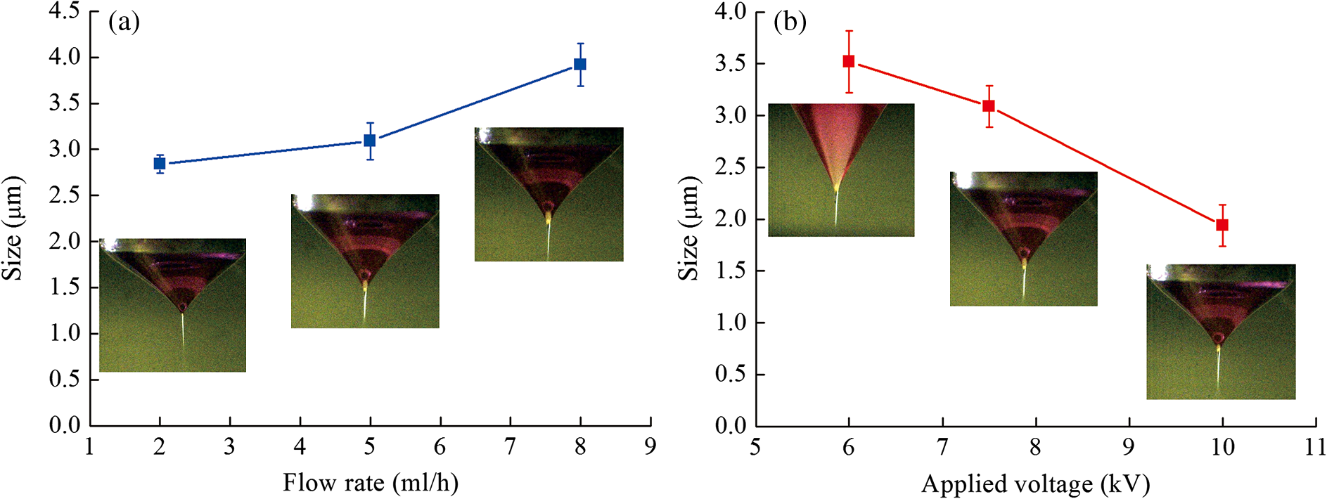 Guided by the above theoretical analysis, we have carried out the coaxial electrospray experiment under different test conditions. In one experiment, the multilayered PLGA microparticles have been fabricated using the following process parameters: (1) the applied positive voltage is 3 kV; (2) the applied negative voltage is 10 kV; (3) the flow rate of the outer PLGA solution is ; (4) the flow rate of the inner distilled water and ethylene glycol is ; and (5) the vertical distances from the outer needle to the top and the bottom electrodes are 0.25 and 10 cm, respectively. Nile red is dissolved in the PLGA solution for fluorescence visualization of the core–shell structure. The fabricated microparticles are centrifugated and freeze dried before imaging. According to the scanning electron microscopic (SEM) image in Fig. 8(a), coaxial electrospray yields microparticles with nearly uniform size and satisfactory morphology. According to the confocal fluorescence microscopic image in Fig. 8(b), the fabricated microparticles have a clearly identifiable core–shell structure. The averaged size of the main microparticles produced by the coaxial electrospray in this experiment is , as plotted in Fig. 8(c). Fig. 8(a) Scanning electron microscopic image of the PLGA microparticles fabricated by coaxial electrospray (the inset at the upper-right corner is the zoomed image of a single broken microparticle clearly showing its core–shell structure). (b) Confocal microscopic image of the PLGA microparticles showing the fluorescence emission of Nile red in the shell. (c) Size distribution of the produced microparticles. The following parameters are used in the experiment: (1) the applied positive voltage is 3 kV; (2) the applied negative voltage is 10 kV; (3) the flow rate of the outer 100 mg/ml PLGA solution is ; (4) the flow rate of the inner distilled water and ethylene glycol is ; and (5) the vertical distances from the outer needle to the top and the bottom electrodes are 0.25 and 10 cm, respectively. The scale bar is 20 μm. 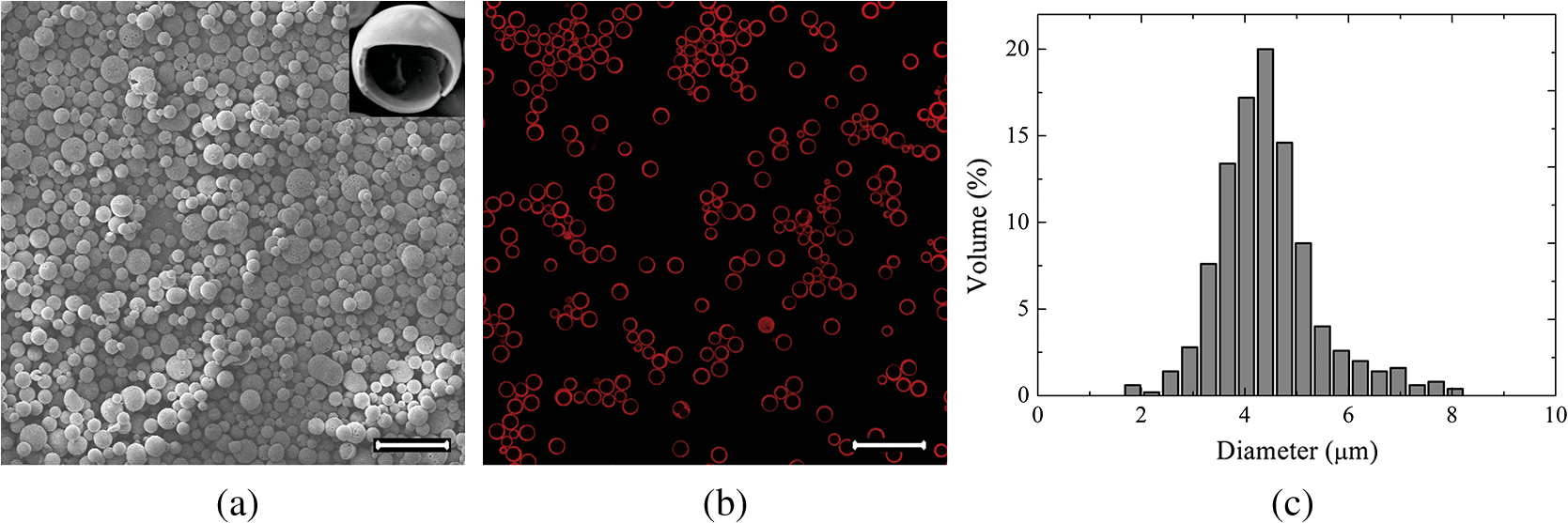 4.Conclusions and PerspectivesCoaxial electrospray is an emerging process with the capability to encapsulate multiple imaging and therapeutic agents in multilayered micro- and nanoparticles. In comparison with the conventional micro-encapsulation processes, this process has the advantages of nearly 100% encapsulation rate, narrow particle size distribution, and preserved bioactivity for the encapsulated therapeutic agents. Despite the above advantages, broader dissemination of this novel micro-encapsulation process is still hampered by the multiphysical nature and the complex interplays of the process. From the experimental perspective, a coaxial electrospray process involves a number of process parameters and material properties that are coupled with each other. These parameters can be further categorized into the following three groups: geometric parameters (e.g., the structure of coaxial needle assembly and the distance between outer needle and two electrodes from top to bottom), material properties (e.g., density, surface tension coefficient, conductivity, and permittivity profiles for the inner and the outer liquids), and other control variables (e.g., the inner and the outer flow rates, the applied voltages between positive electrode, ground and negative electrode). Inline monitoring or optimization of all these parameters is challenged by the lack of effective measurement tools and the coupling of the process parameters. To overcome this challenge, we choose to vary two measurable and controllable parameters (i.e., the applied negative voltage, and the outer flow rate) while keeping the others constant. These two parameters are also primary factors contributing to the morphology of the produced microparticles. From the theoretical perspective, we use instability analysis to reveal the flow response to disturbances with small amplitudes superposed on a laminar basic flow of a presumed velocity profile. The analysis yields dimensionless variables helpful for the prediction of the liquid jet breakup but not directly correlated with their morphologic characteristics. Owing to this reason, it is difficult to establish quantitative process guidance through instability analysis at the current stage. Previous studies have been focused on either fabrication or theoretical aspects, without considering the correlation between them. We are among the first to integrate numerical analysis and experimental design in coaxial electrospray. Experimentally, we have custom designed a coaxial needle assembly for a stable cone-jet mode within a broad range of the adjustable process parameters. Theoretically, we have adopted a classical method of expansion of normal modes with simplification for instability analysis of the coaxial electrified jet. The experimental development and the theoretical analysis are integrated in a coaxial electrospray process in order to understand the mechanism for jet breakup and to study the effects of process parameters on the formation of the unstable modes. The knowledge we gained from this preliminary study will help us to develop better experimental and numerical tools in the future for successive improvement of the process outcome. Further experimental and theoretical investigations are necessary before a complete design and control strategy can be deployed for mass production of multilayered and drug-loaded micro- and nanoparticles with satisfactory morphology, nearly uniform size distribution, optimal loading capacity, and superior core–shell structure. AcknowledgmentsThis project was sponsored by the Natural Science Foundation of China (Project No. 11002139 to Si), National Cancer Institute (Grant No. R21CA15977 to Xu), and Ohio Lion’s Eye Research Foundation (Fellowship support to Zhang). Fruitful discussions with Dr. Fang Li are greatly appreciated. ReferencesR. A. Jain,
“The manufacturing techniques of various drug loaded biodegradable poly(lactide-co-glycolide) (PLGA) devices,”
Biomaterials, 21
(23), 2475
–2490
(2000). http://dx.doi.org/10.1016/S0142-9612(00)00115-0 BIMADU 0142-9612 Google Scholar
R. C. Mundargiet al.,
“Nano/micro technologies for delivering macromolecular therapeutics using poly(d,l-lactide-co-glycolide) and its derivatives,”
J. Controlled Release, 125
(3), 193
–209
(2008). http://dx.doi.org/10.1016/j.jconrel.2007.09.013 JCREEC 0168-3659 Google Scholar
H. K. Sajjaet al.,
“Development of multifunctional nanoparticles for targeted drug delivery and noninvasive imaging of therapeutic effect,”
Curr. Drug Discov. Technol, 6
(1), 43
–51
(2009). http://dx.doi.org/10.2174/157016309787581066 CDDTAF 1570-1638 Google Scholar
C. E. AsteteC. M. Sabliov,
“Synthesis and characterization of PLGA nanoparticles,”
J. Biomater. Sci., Polym. Ed., 17
(3), 247
–289
(2006). http://dx.doi.org/10.1163/156856206775997322 JBSEEA 0920-5063 Google Scholar
R. B. Campbell,
“Tumor physiology and delivery of nanopharmaceuticals,”
Anticancer Agents Med. Chem., 6
(6), 503
–512
(2006). http://dx.doi.org/10.2174/187152006778699077 AAMCE4 1871-5206 Google Scholar
K. FerraraR. PollardM. Borden,
“Ultrasound microbubble contrast agents: fundamentals and application to gene and drug delivery,”
Annu. Rev. Biomed. Eng., 9 415
–447
(2007). http://dx.doi.org/10.1146/annurev.bioeng.8.061505.095852 ARBEF7 1523-9829 Google Scholar
R. X. Xuet al.,
“Fabrication of indocyanine green encapsulated biodegradable microbubbles for structural and functional imaging of cancer,”
J. Biomed. Opt., 14
(3), 034020
(2009). http://dx.doi.org/10.1117/1.3147424 JBOPFO 1083-3668 Google Scholar
J. HuangJ. S. XuR. X. Xu,
“Heat-sensitive microbubbles for intraoperative assessment of cancer ablation margins,”
Biomaterials, 31
(6), 1278
–1286
(2010). http://dx.doi.org/10.1016/j.biomaterials.2009.11.008 BIMADU 0142-9612 Google Scholar
J. S. Xuet al.,
“Synthesizing and binding dual-mode poly (lactic-co-glycolic acid) (PLGA) nanobubbles for cancer targeting and imaging,”
Biomaterials, 31
(7), 1716
–1722
(2010). http://dx.doi.org/10.1016/j.biomaterials.2009.11.052 BIMADU 0142-9612 Google Scholar
R. Xuet al.,
“Drug-loaded biodegradable microspheres for image-guided combinatory epigenetic therapy,”
J. Biomed. Opt., 16
(2), 020507
(2011). http://dx.doi.org/10.1117/1.3548878 JBOPFO 1083-3668 Google Scholar
I. G. Loscertaleset al.,
“Micro/nano encapsulation via electrified coaxial liquid jets,”
Science, 295
(5560), 1695
–1698
(2002). http://dx.doi.org/10.1126/science.1067595 SCIEAS 0036-8075 Google Scholar
L. Zhanget al.,
“Coaxial electrospray of microparticles and nanoparticles for biomedical applications,”
Expert Rev. Med. Devices, 9
(6), 595
–612
(2012). http://dx.doi.org/10.1586/erd.12.58 1743-4440 Google Scholar
S. P. Lin, Breakup of Liquid Sheets and Jets, Cambridge University Press, Cambridge, United Kingdom
(2003). Google Scholar
T. Siet al.,
“Modes in flow focusing and instability of coaxial liquid–gas jets,”
J. Fluid Mech., 629 1
–23
(2009). http://dx.doi.org/10.1017/S0022112009006211 JFLSA7 0022-1120 Google Scholar
F. LiX. Y. YinX. Z. Yin,
“Linear instability of a coflowing jet under an axial electric field,”
Phys. Rev. E: Stat. Nonlinear Soft Matter Phys., 74
(3 Pt. 2), 036304
(2006). http://dx.doi.org/10.1103/PhysRevE.74.036304 PLEEE8 1539-3755 Google Scholar
F. LiX. YinX. Yin,
“Axisymmetric and non-axisymmetric instability of a coflowing jet under an axial electrified field,”
J. Fluid Mech., 632 199
–225
(2009). http://dx.doi.org/10.1017/S0022112009006429 JFLSA7 0022-1120 Google Scholar
J. M. Lopez-Herreraet al.,
“Coaxial jets generated from electrified Taylor cones. Scaling laws,”
J. Aerosol Sci., 34
(5), 535
–552
(2003). http://dx.doi.org/10.1016/S0021-8502(03)00021-1 JALSB7 0021-8502 Google Scholar
A. G. Marinet al.,
“Simple and double emulsions via coaxial jet electrosprays,”
Phys. Rev. Lett., 98
(1), 014502
(2007). http://dx.doi.org/10.1103/PhysRevLett.98.014502 PRLTAO 0031-9007 Google Scholar
|


