|
|
1.IntroductionOne in eight women in America will be affected by breast cancer during their lives.1 The disease causes morphological changes, which can be seen in histologic images after removing intact tissue or aspirating cells. Pathologists use bench-top microscopes to classify tissue as benign, carcinoma in situ, or invasive cancer2,3 and to grade cancer, if it is detected. Endomicroscopes provide an alternative to conventional biopsies by providing microscopic images of in vivo tissue in real time. Techniques for performing these “optical biopsies” include confocal laser endomicroscopy,4 nonlinear endomicroscopy,5 and HiLo microscopy (“Hi” and “Lo” referring to, respectively, the uniform and speckled illumination techniques used to create optically sectioned images).6 This technology has led to commercial products, notably endomicroscopes from Mauna Kea Technologies, Paris, France,7 Pentax, Tokyo, Japan,8 and Optiscan, Notting Hill, Victoria, Australia.9 This article builds on previous work with a high-resolution microendoscope (HRME), a fiber optic fluorescence microscope which captures an image of tissue in direct contact with the distal tip of the fiber bundle. A number of studies have shown that, following application of a fluorescent dye, HRME imaging can be used to visualize subcellular morphology and epithelial architecture to identify precancerous lesions in the oral cavity,10 esophagus,11 and cervix.12 While HRME imaging provides adequate resolution and contrast to identify neoplasia in these tissues, the lateral resolution is insufficient to resolve some subcellular features of interest. The lateral resolution of the HRME is limited to 7.8 μm by the core-to-core spacing of the fiber bundle, as demonstrated in Sec. 4. In contrast, pathologists usually begin examining tissue with low-magnification microscope objectives (between and ) with low numerical aperture (NA) (typically NA0.1 to NA0.15) providing 2 to 3-μm resolution. Moreover, while the contrast of HRME images is high in squamous epithelial tissue, contrast is poorer in dense scattering tissue such as breast tissue. Here, we present an improved HRME that incorporates an ultra-slim, achromatic objective composed of plastic lenses at the fiber bundle’s distal tip. The outer diameter (OD) of the optomechanics is 2.1 mm, matching the OD of a 14-gauge core biopsy needle. The objective magnifies an image of the tissue onto the image guide by and increasing sampling and improving lateral resolution to 4.4 μm. While others have reported the use of a gradient index (GRIN) to improve spatial resolution, using a custom, achromatized objective, rather than a monochromatic GRIN lens, can improve the collection efficiency when there is a Stokes shift5 allowing the contrast of fluorescence images to be improved by co-localizing excitation and emission planes. To the best of our knowledge, the high NA, plastic achromatic objective is the first of its type at this scale. The improved HRME utilizes structured illumination to perform optical sectioning, which reduces out-of-focus light, thereby improving image contrast, especially when imaging turbid tissue. The structured illumination HRME (SI-HRME) projects a translatable grid pattern onto the proximal face of the fiber bundle, similar to Bozinovic et al.13 Three intensity-modulated images are captured, each with the grid pattern one-third out of phase from the other two, by mechanically translating the grid by one-third of the period. The modulated images are recombined to form a single, optically sectioned image. We demonstrate the use of this needle-sized probe to provide real-time images of breast tissue with significantly improved resolution and contrast compared with a standard endomicroscope. This can allow a diagnosis to be made immediately and without tissue removal. Because the objective is achromatic, in the future it can be used to image multiple dyes and multiple wavelengths simultaneously, though currently it is only demonstrated with a single fluorescent dye. The improved endomicroscope provides a step forward for needle-based, in vivo microscopy. 2.Designing the Achromatic, Ultra-Slim Objective and the SI-HRMEThe system was constructed by designing, fabricating, and characterizing an ultra-slim, achromatic objective and assembling an HRME, which achieves optical sectioning via structured illumination. The achromatic objective is related to a design in our previously published work.14 The earlier work demonstrated an achromatic plastic microscope objective fabricated in 20-mm diameter discs as a proof of design. This prototype objective was tested only using benchtop, commercial microscopes. The current objective is a 2.1-mm OD achromatic objective, which is attached to the distal tip of the SI-HRME. This work details the re-optimized design of the achromatic objective, the fabrication and characterization of 2.1-mm plastic doublets, the integration of the objective into an endomicroscope with optical sectioning, and the initial tissue imaging with the integrated system. 2.1.Specifications for the Achromatic, Ultra-Slim ObjectiveThe design specifications for the achromatic objective are listed in Table 1. The optical requirements are similar to those described in our previous work.14 However, the current objective has a higher NA and a larger FOV, which were accomplished by relaxing the maximum clear aperture requirement from 0.9 to 1.5 mm. The increased clear aperture means the assembled objective is as wide as a 14-gauge core biopsy needle, rather than the 18-guage objective we previously reported.15 In addition to providing a smaller diffraction-limited spot size and larger imaging area, the new objective’s higher object space NA and lower magnification cause the image space NA to more closely match the NA0.35 fiber bundle (improving the light collection efficiency). Table 1Design specifications of the NA0.55 achromatic, ultra-slim objective.
The object space NA0.55 means the objective will have a point spread function (PSF) size of 1.14 μm at the 515-nm emission peak of proflavine, a fluorescent dye which stains cell nuclei, allowing visualization of the size and the shape of each nucleus. In image space, the PSF size is 2.28 μm, which is still well beneath the 3.8-μm core-to-core spacing of the individual fibers in the fiber bundle. This sampling frequency, combined with the magnification, means the lateral resolution of the endomicroscope will be approximately 3.8 μm. A 360-μm FOV is matched onto the 720-μm active diameter of the image guide by the magnification. The short 15-μm working distance allows the objective to image tissue in contact with the first lens. Achromatizing brings the excitation and the emission planes of proflavine to the same focal plane, which can improve the collection efficiency.5 Also, a wavelength range from 452 to 623 nm allows the achromatic objective to work with proflavine and cresyl violet, simultaneously.14 The objective is telecentric in object space, and nearly so in image space. Landau et al.16 reported that maintaining telecentricity in image space for such narrow objectives would compromise transverse magnification and performance at the edge of the FOV. Varying the principle ray angle from 0 deg, though it leads to some vignetting, helps to maintain higher image quality than if the design was doubly telecentric. An objective meeting the requirements in Table 1 was designed in ZEMAX (Radiant Zemax, LLC., Redmond, Washington). The layout of the design is displayed in Fig. 1. The objective is composed of six plastic lenses. The detailed analysis for selecting the specific plastics has been thoroughly described elsewhere14,15,17 and includes low autofluorescence for the design wavelengths, high transmission, ease of fabricating aspheres, and the potential for mass production via injection molding. Zeonex E48R and PMMA are both crown-like plastics, while polystyrene behaves optically like a flint. Zeonex E48R also has very low water absorption, which is why it was selected to be in contact with tissue. Lenses 2 and 3 form an achromatic doublet of PMMA and polystyrene with the optical adhesive NOA61 acting as the cement, and lenses 4 and 5 do the same. 2.2.Nominal and Expected Performance of the Achromatic, Ultra-Slim ObjectiveThe nominal performance of the objective is shown in Fig. 2. The modulation transfer function (MTF) in Fig. 2(a) shows that the objective maintains diffraction-limited performance across the FOV. It accomplishes this in part by assuming a curved object; this is permissible because the sag in object space is less than the thickness of a typical breast cell. The chromatic focal shift plotted in Fig. 2(b) confirms that the objective is achromatic. Also, the 6.0-μm diffraction-limited range is larger than the 4.0-μm maximum chromatic focal shift. The design was thoroughly toleranced in ZEMAX. The tolerances listed in Table 2 were estimated based on in-house fabrication capabilities of an ultra-precision lathe. The lenses were formed via single-point diamond turning (SPDT). For injection molding, the tolerances are considered commercial or state-of-the-art.18 Table 2Tolerance values for the NA0.55 needle achromatic objective.
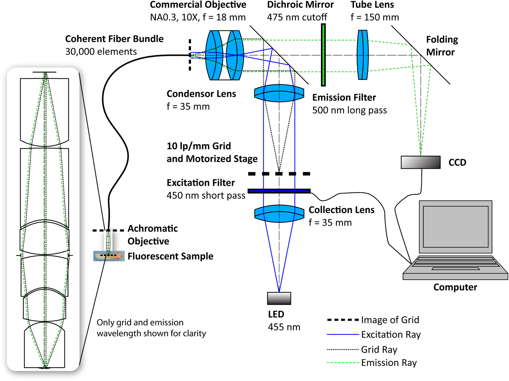
2.3.Specifications for the SI-HRMEFigure 3 shows a schematic for the endomicroscope. The excitation light is generated by a blue LED (M455L2, Thorlabs, Newton, New Jersey) at 455 nm and passes through a grid (59–545, Edmund Optics Inc., Barrington, New Jersey) on a motorized stage (T-LS28E, Zaber Technologies Inc., Vancouver, British Colombia, Canada). An image of the grid is focused onto the proximal face of a fiber bundle (FTIFHR800S, F & T Fibers and Technology GmbH, Berlin, Germany) with an NA0.3 commercial objective (RMS10X-PF, Thorlabs). The grid’s image is relayed through the fiber bundle and focused onto the fluorescent sample by the integrated objective. The modulated emission light returns through the system and is imaged onto a charge-coupled device camera (GRAS-14S5M, Point Grey Research, Inc., Richmond, British Colombia, Canada), where it is reconstructed into an optically sectioned image. When the grid is outside the path of the excitation light, the system is functionally identical to a conventional HRME. The SI-HRME can take advantage of this by using the motorized stage to translate the grid out of the light path; this allows conventional HRME images to be compared with SI-HRME images with identical FOVs without the need for a separate imaging system. 3.Fabrication of the EndomicroscopeBecause the plastic lenses were fabricated via SPDT, the optical surfaces and alignment features can be produced at the same time allowing tight manufacturing tolerances to be maintained.14,17 A CAD model based on the optical design was made in SolidWorks (Dassault Systèmes SolidWorks Corp., Waltham, Massachusetts) [Figs. 4(a) and 4(b)]. The OD of the lenses and optomechanics in Fig. 4 is 2.1 mm, which matches the OD of 14-gauge core biopsy needles. Fig. 4(a) SolidWorks cutaway of the achromatic objective with built-in alignment features. (b) Inset of (a). The alignment features at the edges define the position of the lenses. (c) SolidWorks model of the achromatic objective and the fiber coupler used to attach the objective to the fiber bundle. 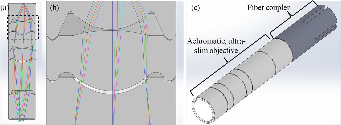 The circular ridges and rounded V grooves visible at the edges of Fig. 4(b) allow the lenses to be assembled with no alignment necessary (a zero alignment technique14,17,19). The alignment features uniquely define the position of the lenses laterally and axially, allowing them to be stacked one atop the other and glued in place. To create the doublet lenses, a small drop of NOA61 is added to the concave optical surface before the two singlets are stacked. Once both lenses are in place, the adhesive is cured via UV exposure. The remaining lenses are stacked without adding adhesive. Once the alignment features are mated, the lenses are held in place and a small amount of cyanoacrylate is added to the outer edge of the alignment features and allowed to set. This procedure creates a strong, water-tight bond. To integrate the objective and the fiber bundle, a custom fiber coupler was also designed in SolidWorks and is shown mated with the achromatic objective in Fig. 4(c). The fiber coupler is a hollow, optomechanical part which was fabricated in plastic with a three-dimensional printer (Pro Jet SD 3000, 3D Systems, Inc., Rock Hill, South Carolina) and has the same OD as the achromatic objective. The inner diameter matches the diameter of the fiber bundle. A rounded V groove, matching those in Fig. 4(b), was cut into the distal face via SPDT, allowing the achromatic objective to be attached to the fiber coupler using cyanoacrylate as described above. To position the fiber bundle face at the image plane of the achromatic objective, the fiber bundle was translated along the optical axis, while the achromatic objective imaged a resolution target; at the best focal position, the fiber coupler was set in place with epoxy, creating an integrated imaging system. 3.1.Measuring the Tilt and Decenter of Ultra-Slim Doublet LensesBefore assembling a complete objective, five sample doublet lenses were made to validate the custom alignment features’ abilities to create systems which meet the given tolerances. Each doublet was fabricated as described above, using flat optical surfaces to facilitate tilt and decenter measurements. To measure tilt, each doublet was placed on a microscope slide beneath a NewView 5020 white light interferometer (Zygo Corp., Middlefield, Connecticut) after the tilt of the stage was reduced to [Fig. 5(a)]. The tilt of each doublet was measured five times and averaged. The average tilt of the five doublets was 0.17 deg with a standard deviation of 0.07 deg. Fig. 5(a) Sample doublet undergoing tilt measurements with a Zygo white light interferometer. (b) Sample doublet undergoing decenter measurements with a Zeiss microscope. (c) Set of lenses ready for assembly, fully assembled achromatic objective, and a commercial objective, next to a ruler for scale.  To measure the decenter, each doublet was placed on a microscope slide beneath an Imager.Z1 upright microscope (Carl Zeiss, Oberkochen, Germany) [Fig. 5(b)]. Images of the first and the last surfaces were captured without adjusting the lateral position of the stage or the doublet itself. This process was repeated four more times. The decenter between each doublet was measured by using ImageJ to find the center of each surface and to calculate the displacement between pairs of surfaces. The average decenter for the set of doublets was 9.6 μm with a standard deviation of 9.0 μm. When compared with the toleranced values for tilt and decenter, 0.2 deg and 15 μm (Table 2), the measured values indicate that some, though likely not all, of the objectives built will have diffraction-limited performance. These measurements will also allow further optical designs to be more accurately toleranced. 3.2.Validation Setup of the SI-HRME with an Integrated Achromatic Ultra-Slim ObjectiveA complete set of individual lenses and an assembled achromatic objective are shown in Fig. 5(c). A layer of heat shrink tubing was added to block outside light from entering the system and to improve the objective’s durability. To reduce stray light through the system, baffles were added within the objective by applying permanent marker up to the edges of the optical surfaces [the blue surfaces in Fig. 5(c)]. An integrated achromatic objective is shown in Fig. 6(a). The fully assembled SI-HRME is shown in Fig. 6(b) and matches the schematic in Fig. 3. 4.Achromatic Objective and Integrated SI-HRME ResultsBefore incorporating the ultra-slim, achromatic objective into the SI-HRME, the objective’s performance was characterized by imaging a fluorescent resolution target and by measuring the chromatic focal shift. Next, the lateral resolution of the SI-HMRE was measured before and after integrating the achromatic objective. Finally, the integrated endomicroscope’s performance was evaluated by imaging ex vivo normal and neoplastic murine mammary tissues. 4.1.Achromatic, Ultra-Slim Objective PerformanceThe performance of the achromatic objective was characterized before incorporating it into the endomicroscope. Images from the custom objective were relayed through an Imager.Z1 upright microscope as shown in Fig. 7(a). A fluorescent 1951 USAF resolution target (38–256, Edmund Optics Inc.) was placed at the object plane of the custom objective; while in water immersion, an image of the target was relayed with a NA0.45 objective (Carl Zeiss). An example image showing good performance is displayed in Fig. 7(b). There is some loss of resolution at the edge of the FOV; this is because the objective is designed to image a curved object, and the target is flat. Adjusting the focal plane by a few microns brings the edge features into sharp focus. Fig. 7(a) Commercial Zeiss microscope objective relaying images from the custom achromatic objective. (b) Fluorescence image of a 1951 USAF resolution target imaged through the achromatic objective.  To ensure that the custom objective is achromatized, the chromatic focal shift was measured. A VariSpec liquid crystal tunable filter (Cambridge Research & Instrumentation, Inc., Hopkinton, Massachusetts) was used to provide narrowband illumination starting at 450 nm. A resolution target was brought into focus, and the objective’s position was measured. This procedure was performed in 20-nm steps up to 630 nm, and then repeated four times. The average chromatic focal shift is plotted below along with the nominal chromatic focal shift (Fig. 8). The measurements demonstrate that the objective is achromatic, though the chromatic focal shift range of 6.9 μm is slightly larger than the 6.0-μm diffraction-limited shift range. This analysis was compared with a different custom, ultra-slim NA0.55 plastic objective that conforms to the specifications in Table 1, except that it is designed for only a single wavelength; it is optimized for 515 nm, the emission peak of proflavine, and performs well at this wavelength. The nominal chromatic focal shift for the monochromatic objective is 96.7 μm, more than an order of magnitude greater than the diffraction-limited shift range. The excitation and the emission peaks of proflavine are marked on the measured achromatic objective plot () and on the nominal monochromatic objective plot (+). Note that the peaks are within the diffraction-limited range for the achromatic objective and are outside this range for the monochromatic objective. Fig. 8The diffraction limited depth of field for a , NA0.55 objective represented by the gray rectangle is 6.0 μm. The nominal shift range plotted by the solid line is 4.0 μm. The measured shift range plotted by the small dashed line is 6.9 μm. The nominal shift range of an NA0.55 monochromatic objective plotted by the large dashed line is 96.7 μm.  Achromatizing the objective keeps the contrast of the structured illumination grid pattern near the diffraction limit. The pattern, which has a frequency of in the image plane of the custom objective, has expected contrasts of approximately 0.98 at 452 nm and 0.97 at 515 nm, which leads to a high-intensity, optically sectioned image. The monochromatic objective’s expected contrast at 452 nm is also 0.98, but the contrast at 515 nm has dropped to approximately 0.70, indicating a weaker-structured illumination signal. 4.2.Performance of the Integrated SI-HRMEThe lateral resolution limit of the endomicroscope was measured before and after integrating the achromatic objective (Fig. 9). With only a bare fiber bundle, the SI-HRME is limited by the fiber spacing, and the smallest resolvable features on the USAF 1951 resolution target are group 7, element 1 [Fig. 9(a)] indicating a resolution limit of 7.8 μm. With the achromatic objective at the distal tip, the effective fiber spacing at the object is doubled due to the objective’s magnification. All features on the target are resolvable [Fig. 9(b)] indicating a resolution of at least 4.4 μm (this nearly matches the expected 3.9-μm resolution limit). Fig. 9Fluorescence images of a 1951 USAF resolution target through the HRME (a) before integrating the achromatic objective to the distal tip of the fiber bundle and (b) after integrating the objective. The lateral resolution limit improves from 7.8 μm (group 7, element 1) to 4.4 μm (group 7, element 6).  4.3.Imaging Results with the Integrated SI-HRMEThe endomicroscope’s ability to image breast tissue was evaluated using freshly resected murine mammary tissue. A non-neoplastic murine mammary gland and a murine mammary gland bearing an invasive carcinoma lesion were sliced to a thickness of approximately 300 μm using a tissue slicer (Krumdieck MD4000, Alabama Research and Development, Munford, Alabama), stained with a 0.05% proflavine solution for 5 min before washing with PBS (Sigma-Aldrich Co., St. Louis, Missouri), and then imaged with an excitation of 488 nm using the Vivascope 2500 confocal microscope (Caliber Imaging and Diagnostics Inc., Rochester, New York). Once imaging with the confocal microscope was complete, regions of interest from the ex vivo sample were imaged with the integrated SI-HRME both with and without optical sectioning via structured illumination. Selected sites were matched, and the results are shown in Fig. 10. Each row shows images which were obtained from the same tissue slice, and attempts to match the FOV. The same region of interest is guaranteed for the conventional HRME and the SI-HRME, because the fiber bundle is held in place at a region of interest while the grid is translated into or out of the path of the excitation light. However, minor morphological changes in the tissue lead to some uncertainty when matching the FOV for images from the confocal microscope. Even when the FOV is not precisely matched, the selected features provide a viable comparison between the various modalities. Cells are visible in the images of the neoplastic mammary tissue obtained with all three systems. However, in the denser, more highly scattering tumor specimens, image contrast is degraded in the conventional HRME images, and individual cells cannot be resolved. The SI-HRME improves contrast, and individual tumor cells can clearly be resolved providing images with similar quality to those images obtained with benchtop confocal microscopy. Note that there is greater contrast improvement for the tumor images, which are dense with nuclei, than for the relatively sparse normal tissue images. 5.ConclusionsAn improved endomicroscope using structured illumination to achieve optical sectioning and which integrates a custom achromatic, ultra-slim objective was demonstrated. While the assembled lenses have the same OD as a core biopsy needle, adding heat shrink tubing causes the objective to be too wide. In the future, the OD of the optomechanical design will be reduced by 150 μm to fit within a 14-gauge (2.1 mm) hypodermic needle with an inner diameter of 1.96 mm. This would improve the strength of the integrated endomicroscope and allow the probe to pierce tissue. Although the magnification could also be increased, further improving the resolution of the system, it would also further reduce the FOV; increasing resolution is balanced with decreasing FOV for any given fiber bundle. Adding an objective to the distal tip of the fiber bundle improved the spatial resolution of the system, while structured illumination was used to reduce out-of-focus light and to improve the contrast of turbid samples. The endomicroscope was successfully demonstrated on freshly resected murine mammary tissue stained with proflavine. The SI-HRME can provide a technique for improving in vivo imaging. AcknowledgmentsFunding was provided by NIH grants R01 EB007594, R01 CA103830, and R01 CA124319 and by the Susan G. Komen Promise Grant KG091020. References, “Breast Cancer Risk in American Women,”
(2013) http://www.cancer.gov/cancertopics/factsheet/detection/probability-breast-cancer January ). 2013). Google Scholar
Y. Cuiet al.,
“Nuclear morphometric features in benign breast tissue and risk of subsequent breast cancer,”
Breast Cancer Res. Treat., 104
(1), 103
–107
(2007). http://dx.doi.org/10.1007/s10549-006-9396-4 BCTRD6 Google Scholar
L. Mariuzziet al.,
“Quantitative study of breast cancer progression: different pathways for various in situ cancers,”
Mod. Pathol., 15
(1), 18
–25
(2002). http://dx.doi.org/10.1038/modpathol.3880485 MODPEO 0893-3952 Google Scholar
K. DunbarM. Canto,
“Confocal endomicroscopy,”
Curr. Opin. Gastroenterol., 24
(5), 631
–637
(2008). http://dx.doi.org/10.1097/MOG.0b013e32830c91c7 COGAEK 0267-1379 Google Scholar
Y. Wuet al.,
“Scanning fiber-optic nonlinear endomicroscopy with miniature aspherical compound lens and multimode fiber collector,”
Opt. Lett., 34
(7), 953
–955
(2009). http://dx.doi.org/10.1364/OL.34.000953 OPLEDP 0146-9592 Google Scholar
S. Santoset al.,
“Optically sectioned fluorescence endomicroscopy with hybrid-illumination imaging through a flexible fiber bundle,”
J. Biomed. Opt., 14
(3), 030502
(2009). http://dx.doi.org/10.1117/1.3130266 JBOPFO 1083-3668 Google Scholar
M. J. Waldneret al.,
“Confocal laser endomicroscopy and narrow-band imaging-aided endoscopy for in vivo imaging of colitis and colon cancer in mice,”
Nat. Protoc., 6
(9), 1471
–1481
(2011). http://dx.doi.org/10.1038/nprot.2011.377 NPARDW 1750-2799 Google Scholar
K. B. Dunbaret al.,
“Confocal laser endomicroscopy in Barrett’s esophagus and endoscopically inapparent Barrett’s neoplasia: a prospective, randomized, double-blind, controlled, crossover trial,”
Gastrointest. Endosc., 70
(4), 645
–654
(2009). http://dx.doi.org/10.1016/j.gie.2009.02.009 GAENBQ 0016-5107 Google Scholar
M. Goetzet al.,
“Simultaneous confocal laser endomicroscopy and chromoendoscopy with topical cresyl violet,”
Gastrointest. Endosc., 70
(5), 959
–968
(2009). http://dx.doi.org/10.1016/j.gie.2009.04.016 GAENBQ 0016-5107 Google Scholar
M. C. Pierceet al.,
“Accuracy of in vivo multimodal optical imaging for detection of oral neoplasia,”
Cancer Prev. Res., 5
(6), 801
–809
(2012). http://dx.doi.org/10.1158/1940-6207.CAPR-11-0555 CPRACC 1940-6207 Google Scholar
M. H. Leeet al.,
“Advanced endoscopic imaging for Barrett’s Esophagus: current options and future directions,”
Curr. Gastroenterol. Rep., 14
(3), 216
–225
(2012). http://dx.doi.org/10.1007/s11894-012-0259-3 1522-8037 Google Scholar
M. C. Pierceet al.,
“A pilot study of low-cost, high-resolution microendoscopy as a tool for identifying women with cervical precancer,”
Cancer Prev. Res., 5
(11), 1273
–1279
(2012). http://dx.doi.org/10.1158/1940-6207.CAPR-12-0221 CPRACC 1940-6207 Google Scholar
N. Bozinovicet al.,
“Fluorescence endomicroscopy with structured illumination,”
Opt. Express, 16
(11), 8016
–8025
(2008). http://dx.doi.org/10.1364/OE.16.008016 OPEXFF 1094-4087 Google Scholar
M. KyrishT. S. Tkaczyk,
“Achromatized endomicroscope objective for optical biopsy,”
Biomed. Opt. Express, 4
(2), 287
–297
(2013). http://dx.doi.org/10.1364/BOE.4.000287 BOEICL 2156-7085 Google Scholar
M. Kyrishet al.,
“Ultra-slim plastic endomicroscope objective for non-linear microscopy,”
Opt. Express, 19
(8), 7603
–7615
(2011). http://dx.doi.org/10.1364/OE.19.007603 OPEXFF 1094-4087 Google Scholar
S. M. Landauet al.,
“Design and evaluation of an ultra-slim objective for in-vivo deep optical biopsy,”
Opt. Express, 18
(5), 4758
–4775
(2010). http://dx.doi.org/10.1364/OE.18.004758 OPEXFF 1094-4087 Google Scholar
B. McCallet al.,
“Toward a low-cost compact array microscopy platform for detection of tuberculosis,”
Tuberculosis, 91
(Suppl 1), S54
–S60
(2011). http://dx.doi.org/10.1016/j.tube.2011.10.011 Google Scholar
S. Bäumer, Handbook of Plastic Optics, John Wiley & Sons, Hoboken, New Jersey
(2011). Google Scholar
R. T. Kesteret al.,
“Low cost, high performance, self-aligning miniature optical systems,”
Appl. Opt., 48
(18), 3375
–3384
(2009). http://dx.doi.org/10.1364/AO.48.003375 APOPAI 0003-6935 Google Scholar
|