
|
|
|
In biological tissue, light is strongly scattered, which essentially prevents optical focusing beyond one optical transport mean free path ( for human skin).1 Recently, researchers have shown the turbidity of tissue and tissue-like media can be “suppressed” through phase conjugation or wavefront shaping approaches.2 To achieve dynamic optical focusing inside scattering media, a time-reversed ultrasonically encoded (TRUE) optical focusing method has been proposed and implemented.3 In this technique, a focused ultrasound beam is employed to encode those randomly scattered photons that propagate through the ultrasound focus with a shift frequency.4 The ultrasonically encoded light is collected to interfere with a reference beam and form a stationary interferogram inside a holographic material. This material also serves as a phase conjugation mirror (PCM) when a reading beam traveling along the direction opposite to that of the reference beam reads out the hologram from the material. In this way, a phase-conjugated copy of the initial encoded light can be generated. Since all encoded light originates from the ultrasound focus, this time-reversed wavefront eventually converges, although tortuously, back to the ultrasound focal zone, thereby forming an optical focus inside the turbid medium. In previous TRUE systems, two kinds of PCMs were adopted to time-reversed light.3,5–9 Photorefractive (PR) materials were first used as an analog PCM.3 To match their response time (normally 100 to 200 ms) for holographic recording under continuous wave (CW) illumination, long-ultrasound bursts were employed for modulation,3,5–7 which, however, led to poor focusing resolution along the acoustic axis. More recently, a digital PCM, comprising a fast CMOS camera and a spatial light modulator, was used in combination with the employment of pulsed laser illumination.8,9 The digital PCM enables the use of short ultrasound pulses to achieve tighter focusing along the acoustic axis. Nevertheless, the analog PCM still has its merits, such as higher focus-to-background ratio, faster processing speed, lower implementation cost, and reduced operational complexity.5 In this work, we propose to utilize two intersecting ultrasound beams emitted from two ultrasonic transducers to improve the TRUE optical focusing resolution. These two transducers operate at slightly different frequencies and are aligned such that the ultrasound beams emitted from them intersect at their foci. In this way, the diffuse photons modulated in the intersection zone are frequency shifted by the two ultrasound frequencies and their beat frequencies. Recording the hologram based on the beat frequency-encoded photons and then reading this hologram yields optical focusing to a shrunken volume, and consequently an improved spatial resolution. Figure 1 shows the experimental setup. A CW laser (Coherent, Santa Clara, CA, Verdi V-5) outputs a beam at (its optical frequency is denoted as ). The beam was transmitted through an electro-optic modulator (EOM) and split into two beams by a polarizing beam splitter. The transmitted beam was further split into a signal beam and a collimated reference beam . The beam was collimated as the conjugated reference beam that counter propagated as once reflected by mirror M3. The signal beam was transmitted through two acousto-optic modulators (AOMs), where its optical frequency was tuned to and incident on the tissue-mimicking phantom. Two identical immersion type focused ultrasonic transducers T1 and T2 (Olympus NDT, Waltham, MA, A381S-SU-F1.50IN-PTF) operating in long-burst mode with different frequencies were employed: one at and the other at . The acoustic axis of T1 was aligned along the axis, whereas the acoustic axis of T2 was aligned in the plane. The two ultrasound beams intersected at their foci at an angle of 45 deg, with both acoustic axes perpendicular to the optical axis of the signal beam . The TRUE signal was detected by a photodiode. During the hologram recording stage, when both transducers were used to modulate the signal beam inside the turbid sample, the two AOMs were tuned to match the beat frequency of the transducers so that . The photons initially had an electric field of . Ultrasonic modulation by the two ultrasound beams resulted in photons encoded (or tagged) with different frequency shifts. The spectral components that have frequencies of , , and are the first-order signals and will not interfere with the reference beam to form a stationary interferogram in the (BSO) crystal (Elan, Russia). Inside the intersection volume of the two ultrasound fields, the photons encoded by both ultrasound beams are the second-order signals, which have an electric field of . Some scattered second-order light was collected by two lenses and directed onto the PR crystal, where it interfered with the reference beam , forming a stationary volume hologram. Fig. 1Schematic of the experimental setup. AOM, acousto-optic modulator; BSO, ; EOM, electro-optic modulator; HWP, half-wave plate; L, lens; M, mirror; , signal light; , time-reversed signal light; PBS, polarizing beam splitter; PD, photodiode; , reference beam; , conjugated reference beam; S, shutter; T, ultrasound transducer. Coordinates: , and of T1. The pressure at the ultrasound focus was 1.0 MPa peak-to-peak. To enhance the phase conjugation efficiency, a 2.1-kHz, square waveform external electric field was applied across the BSO.  The holographic recording and reading stages were switched by two shutters, S1 and S2. The timing sequence was set the same as in the previous TRUE system with one .3 Furthermore, the polarization of the laser beam was simultaneously switched between horizontal and vertical states by the EOM to maximize the optical power for holographic recording and reading. To demonstrate the improved focusing resolution along the acoustic axis, we prepared a sandwich-structured phantom, as shown in Fig. 2(a). The dimensions of the phantom are (). A 5-mm-thick scattering layer, having a reduced scattering coefficient of and an absorption coefficient of , was sandwiched between two transparent gelatin gel layers. In the mid- plane of the scattering layer, two 1-mm-thick optical absorbers and a needle were embedded [Fig. 2(b)]. The two absorbers had the same scattering coefficient as the surrounding medium, but a greater absorption coefficient of due to the added India ink. The needle placed near the two absorbers was used to align the two ultrasonic transducers with respect to the two absorbers. Fig. 2Tissue-mimicking phantom to be imaged. (a) The dimensions of the phantom are (). A 5-mm-thick scattering layer with reduced scattering coefficient was sandwiched between two transparent gelatin gel layers. (b) In the mid- plane of the scattering layer, two optical absorbers and a needle were embedded. The two absorbers were made by infusing optically absorbing India ink. The needle was used to align the two ultrasonic transducers with respect to the two absorbers. 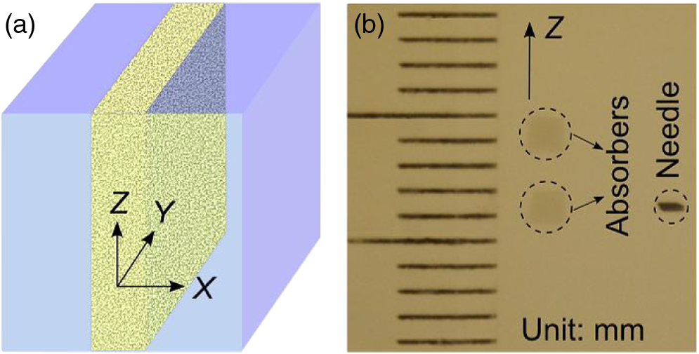 During the experiment, the phantom was scanned along the axis, and the two transducers remained stationary. At each scan position, three signals were recorded successively from the photodiode, and their normalized amplitudes were plotted as a function of the sample position along the axis. First, a time-reversed direct current (TRDC) signal3 was recorded when the AOMs and the ultrasound transducers were turned off. Without ultrasonic tagging that provides spatial resolution, the TRDC plot in Fig. 3(a) shows low image contrast and poor spatial resolution of the two absorbers along the axis as limited by light diffusion inside the turbid sample. Next, with one transducer () was turned on and the AOMs tuned to match the ultrasound frequency so that , the TRUE signal was recorded. With ultrasonic tagging that provides ultrasound resolution, the TRUE image in Fig. 3(b) shows slightly greater details of the two targets than the TRDC image, but the image contrast and the spatial resolution are still poor. Finally, the TRUE signal was recorded with both transducers ( and ) turned on and the AOMs tuned to the beat frequency so that . The TRUE image in Fig. 3(c) shows a much sharper image of the two absorbers, indicating good spatial resolution as a result of the dual ultrasonic modulation in the TRUE process. Fig. 3One-dimensional imaging results of the phantom. (a) Time-reversed direct current (TRDC) image acquired without ultrasound modulation. (b) Time-reversed ultrasonically encoded (TRUE) image acquired using single-transducer (T1) modulation. (c) TRUE image acquired using dual-transducer () modulation. The experimental data were fitted by the theoretic simulations (solid lines). The incident signal beam and the two ultrasonic transducers were stationary, while the phantom was scanned along the axis.  In general, the imaging process of a system can be modeled as1 where is the position along the axis, is the system output amplitude, is the target amplitude, denotes the point spread function (PSF), and * is the convolution operator. The normalized target function describing the two absorbers inside the tissue can be written as10 where denotes the optical absorbance of the targets, denotes the target width, and denotes the separation between the two absorbers’ centers. The square in the first line results from the double passes of light across the target plane in the imaging process. In this experiment, , , , as shown in Fig. 2(b).For TRDC imaging, the PSF represents the diffuse light profile on the target plane, which can be approximated as a Gaussian distribution, whose beam waist was : For TRUE imaging, the PSF represents the amplitude distribution of the ultrasound modulated diffuse photons at the corresponding frequency and can be derived from the equation where is the ultrasound field profile and its square is a result of the light being modulated by the ultrasound field twice in the TRUE imaging process.For single transducer modulation where the sample scans along the transducer’s acoustic axis ( axis), we have1,11 For dual-transducer modulation as configured in our experiment, we have1,11 where and are the respective ultrasound field profiles of the two transducers, , , and is the normalized radial coordinate. denotes the zeroth-order Bessel function of the first kind, denotes the numerical aperture of the transducer, denotes the ultrasonic wavelength, and denotes the angle between the ultrasound beam and the axis. For the transducers used in the experiment, , , for ultrasonic transducer T1 and for ultrasonic transducer T2.The axial resolution in TRUE imaging, defined as the full width at half maximum (FWHM) of the PSF,1 can thus be calculated using Eq. (4). For single-transducer modulation, ; for dual-transducer modulation, , an improvement of 2.4 times. To compare the experimental results with the theoretical prediction, we fitted the experimental data points in Fig. 3 with the simulated output signal curves (shown in solid lines). The optical absorbance A of the targets, determined here as a fitting parameter, turned out to be 0.25, in good agreement with our measurement. The root mean squared error between the fitted curve and the experimental data was calculated to be 0.06. The imaging results suggest that compared to single-transducer encoding, TRUE using dual-transducer modulation can focus diffuse light more tightly along the acoustic axis inside turbid media. With our experimental setup, the axial resolution is improved by a factor of 2.4. It is, however, worth noting that for the single-transducer modulation, the FWHM in our experiment was limited by the diffuse light profile, whose beam waist was 2.6 mm at the target plane, instead of the transducer’s axial resolution of 12.5 mm. So, the axial resolution could be even worse when the diffuse light has a broader spread inside the scattering medium. In comparison, for dual-transducer modulation, the FWHM was limited by the two transducers’ lateral focusing ability in our experiment and will not be affected by a broader diffuse light profile. Moreover, since the improved resolution can be attributed to the overlapping of the two ultrasound beams, an even tighter TRUE focus could be achieved by crossing the two acoustic axes at 90 deg. The signal-to-noise ratio (SNR) obtained by using dual transducers is slightly lower than that obtained by using a single transducer, as shown in Fig. 3. The main reason is the lower modulation depth at the beating frequency. The modulation depth at the beat frequency of the two ultrasound beams is approximately one fifth of that at the fundamental frequency of one ultrasound beam. To overcome the modulation depth limitation, the SNR of TRUE signal could be increased by collecting more ultrasonically encoded scattering light onto the BSO crystal to increase the efficiency of hologram recording. Although BSO does not operate within the preferred red to near infrared optical window for biological tissue imaging, other PR materials such as GaAs and do. This noninvasive method of focusing light with an improved resolution can be used in a wide range of biomedical applications, including optical imaging and photodynamic therapy in deep tissue. AcknowledgmentsThe authors thank Yan Liu for helpful discussions on resolution. We also thank Professor James Ballard for editing the manuscript. This work was conducted at Washington University in Saint Louis, and sponsored in part by National Academies Keck Futures Initiative grant IS 13, and National Institutes of Health grants DP1 EB016986 (NIH Director’s Pioneer Award) and U54 CA136398. ReferencesL. V. WangH. Wu, Biomedical Optics: Principles and Imaging, 11164284
–12169 Wiley, Hoboken, New Jersey
(2007). Google Scholar
A. P. Mosket al.,
“Controlling waves in space and time for imaging and focusing in complex media,”
Nat. Photonics, 6
(5), 283
–292
(2012). http://dx.doi.org/10.1038/nphoton.2012.88 1749-4885 Google Scholar
X. XuH. LiuL. V. Wang,
“Time-reversed ultrasonically encoded optical focusing into scattering media,”
Nat. Photonics, 5
(3), 154
–157
(2011). http://dx.doi.org/10.1038/nphoton.2010.306 1749-4885 Google Scholar
D. S. Elsonet al.,
“Ultrasound-mediated optical tomography: a review of current methods,”
Interface Focus, 1
(4), 632
–648
(2011). http://dx.doi.org/10.1098/rsfs.2011.0021 20428898 Google Scholar
P. Laiet al.,
“Focused fluorescence excitation with time-reversed ultrasonically encoded light and imaging in thick scattering media,”
Laser Phys. Lett., 10
(7), 075604
(2013). http://dx.doi.org/10.1088/1612-2011/10/7/075604 1612-2011 Google Scholar
P. Laiet al.,
“Reflection-mode time-reversed ultrasonically encoded optical focusing into turbid media,”
J. Biomed. Opt., 16
(8), 080505
(2011). http://dx.doi.org/10.1117/1.3609001 JBOPFO 1083-3668 Google Scholar
P. Laiet al.,
“Time-reversed ultrasonically encoded optical focusing in biological tissue,”
J. Biomed. Opt., 17
(3), 030506
(2012). http://dx.doi.org/10.1117/1.JBO.17.3.030506 JBOPFO 1083-3668 Google Scholar
Y. M. Wanget al.,
“Deep-tissue focal fluorescence imaging with digitally time-reversed ultrasound-encoded light,”
Nat. Commun., 3 928
(2012). http://dx.doi.org/10.1038/ncomms1925 NCAOBW 2041-1723 Google Scholar
K. SiR. FiolkaM. Cui,
“Fluorescence imaging beyond the ballistic regime by ultrasound-pulse-guide digital phase conjugation,”
Nat. Photonics, 6
(10), 657
–661
(2012). http://dx.doi.org/10.1038/nphoton.2012.205 1749-4885 Google Scholar
L. L. Zhuet al.,
“Improving the spatial resolution of ultrasound-modulated optical tomography by deconvolution algorithm,”
Proc. SPIE, 5630 819
–822
(2005). http://dx.doi.org/10.1117/12.576934 PSISDG 0277-786X Google Scholar
M. BornE. Wolf, Principles of Optics, 484
–492 Cambridge University Press, New York
(1999). Google Scholar
|


