|
|
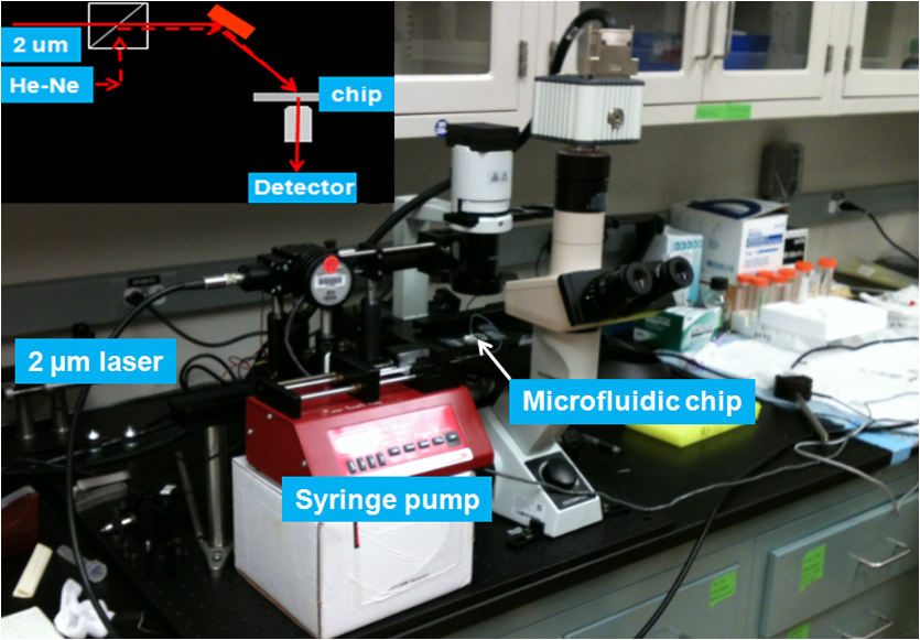
1.IntroductionOptical radiation can impart damage to tissue through a host of biophysical and chemical mechanisms: photothermal, photochemical, and photomechanical. The various forms of laser-induced damage are determined by a combination of factors including the total energy delivered to the tissue, the rate of delivery, the wavelength of light, and the optical properties of the irradiated tissue.1 In addition, it is becoming evident that these different damage mechanisms are not mutually exclusive. For example, oxidative stress has been shown to contribute to overall tissue damage within laser exposures that impart predominately photothermal damage. The complex nature of optical radiation and its ability to elicit damage via multiple mechanisms necessitate a novel approach to the study of laser-tissue interaction, one that comprehensively captures the biochemical state changes occurring in cells following laser exposure. Unfortunately, in the field of laser bioeffects, current assessment of this interaction is largely restricted to an evaluation of the overall damage outcome, whether by coarse visual quantification, microscopic histological analysis of excised tissues, estimates of “viability” using various protocols, and to a lesser extent, analysis of select analytes (e.g., heat shock protein 70) using various reporter constructs.2–5 Critically, an understanding of the cellular and molecular changes that promote well-documented effects associated with laser-tissue interaction remains insufficient. Microfluidic devices offer the possibility of using lower quantities of cells, high throughput, and detailed cellular analysis for laser bioeffects research.6,7 Some of the demonstrated applications of microfluidic systems include cell sorting, cell trapping, cell culture, and electroporation.8 Use of a microfluidic device helps gather individually and similarly treated cells for further molecular analyses. This technique overcomes the faults of the traditional method of single exposures on whole cell populations in a multiwell plate assay. In conventional bioeffect studies, where a multiwell plate is used to irradiate cells, the guassian profile of laser beam produces nonuniform irradiation on the cells. Although flat-top laser beam profiles can be achieved using beam shaper optics, the outputs of many lasers commonly found in laboratories are not powerful enough to produce a uniform beam spot over the entire area of the plate. Using microchannels of a microfluidic device, one needs a beam spot only large enough to cover the width of the channel; hence, laser power requirements are lower and uniform irradiation can be achieved. In this paper, we demonstrate the utility of a microfluidic device to expose mammalian cells to a 2-μm-wavelength laser irradiation. The 2-μm wavelength irradiation was chosen because it is strongly absorbed by water both inside and outside the cell. The result is very rapid heating of extracellular and intracellular water, which causes thermal damage to critical targets within the cell, where the photothermal damage mechanism is dominant.9 Delivery of cells to the laser irradiation spot at a constant velocity is tested. Uniformly laser-treated cells were collected for further analyses, including cell viability and heat shock gene expression. 2.Materials and Methods2.1.Microfluidic Device Design and FabricationThe schematic drawing of the microfluidic device is presented in Fig. 1. It consists of a 6-mm-diameter enclosed inlet reservoir through which cells are injected into the device channel. The injected cells pass through an eight-channel filter assembly where comparatively larger particles are blocked, followed by a bifurcation of the inlet channel leading to two 3-mm-diameter open outlet reservoirs. The dimensions of the various channels are shown in Fig. 1. The device structure is 16 μm in height. We also employed a second design consisting of a multipass filtration system, as shown in the inset of Fig. 1. Polydimethylsiloxane (PDMS, Sylgard 184, Dow Corning, Michigan) was used to make the microfluidic device because it is inexpensive, nontoxic to biological cells, optically transparent down to 230 nm, and easy to fabricate.10 Detailed procedures for fabricating PDMS microfluidic devices can be found in Duffy et al.11 Briefly, the desired design of the microstructure was drawn using a computer-aided design program and professionally printed on transparencies. This transparency was then used as a photomask in UV-photolithography to generate a master mold. A thin layer of SU-8 photoresist (a negative photoresist) was spin-coated on a silicon wafer to a thickness of desired channel height (16 μm in our case). The photoresist was exposed to UV light through the photomask. A developing reagent was used to dissolve the unexposed regions. The resulting structure served as a master mold for fabricating PDMS molds. To create the PDMS mold, the surface of the silicon/photoresist master was treated with fluorinated silanes (which prevent irreversible bonding to PDMS), and a liquid PDMS prepolymer (in a mixture of base polymer: curing agent) was poured onto the photoresist master. Bubbles in the PDMS mixture were removed using a vacuum chamber. The PDMS was cured at 70°C for 1 h and peeled off the master mold, producing the final microstructure design. The as-prepared PDMS surface is highly inert. To make it more adhesive for bonding to glass, a freshly prepared PDMS mold was exposed to oxygen plasma at atmospheric pressure for about 20 s. This breaks some crosslinks at the PDMS surface and makes it more reactive. Before irreversibly bonding the PDMS mold onto a glass slide, a 1-mm hole was punctured at the inlet reservoir and 3-mm holes were punctured at both the outlet reservoirs. Teflon tubing is connected to the inlet reservoir via the 1-mm hole and is sealed with epoxy. The other end of the tubing is attached to a syringe pump (NE-300, New Era Pump Systems Inc., New York) for the delivery of cells. The outlet reservoirs were kept open to manually collect cells using a pipettor. The prepared microfluidic device can be autoclaved to provide a sterile platform for the experiments. One of the two channels is used to expose cells to laser radiation while the other channel is used to collect nonirradiated cells for comparison. 2.2.Cell CultureCultures of Jurkat clone E6-1 (human T-lymphocytes) cells obtained from the American Type Culture Collection (ATCC, Manassas, VA) were maintained at standard growth conditions (37°C; —Air: ) in Roswell Park Memorial Institute (RPMI)-1640 medium supplemented with 10% (v:v) fetal bovine serum, 2 mM l-glutamine, penicillin, and streptomycin. To prepare cells for the microfluidic devices, the cells were harvested during the logarithmic growth phase, pelleted by centrifugation, and resuspended at a desired concentration in a fresh growth medium. 2.3.Experimental SetupThe microfluidic device was placed on the X-Y stage of an inverted microscope with an attached camera. Cells were loaded into the inlet reservoir using a 1-ml monoject syringe, which was placed in a syringe pump. Pumping rates were set at the syringe pump and adjusted to achieve the desired cell flow velocity. Videos of cell flow were recorded at regular intervals to monitor the stability of the cell flow velocity in the microchannel. The 2-μm wavelength beam from a continuous wave fiber optic laser, being invisible, was coaligned with a low power helium-neon laser so that the 2-μm beam spot could be directed without using a near-infrared viewer. The laser beam was directed such that it hit the microchannel at an angle, as shown in the inset of Fig. 2. The spot size of the laser was 0.92 mm in diameter at the surface of the PDMS chip. Once the cell flow velocity was determined to be stable, cells flowing in one of the channels were exposed to the 2-μm laser. Both exposed and unexposed cells were manually collected from the open outlets using a 0.1 to 10 μl pipettor and were stored in 2-ml microcentrifuge tubes. To evaluate cell viability, cells were stained for 10 min with a 1.5-μM solution of calcein AM and ethidium homodimer 1 (EthD-1) in Hanks balanced salt solution and then scored to evaluate the live/dead ratio. Calcein stains live cells green and does not stain dead cells, whereas EthD-1 stains dead cells red but does not stain live cells. 3.Results and DiscussionThe multipass filtration system (Fig. 1, inset) reduced the chances of completely blocking the inlet channel compared to the eight-channel filtration system. This is because the initial filter structures trapped larger particles, if there were any, within those structures, which resulted in keeping the downstream channels open. Achieving the desired cell velocity of was a challenge due to the high flow velocity of cells in the 16-μm-wide channels. Having a tapered channel consisting of varying dimensions before the bifurcation also contributed to undesired flow rates. Therefore, the channel design was modified by increasing the channel width to 150 μm while making it uniform throughout the device except at the filter area. This enabled a better control of the flow of cells. Instead of irradiating a single cell at a time, this new design allowed us to irradiate several cells at once while still achieving uniform irradiance on every cell passing through the channel under the laser beam spot. We discovered that maintaining a stable critical cell flow rate throughout the period of a particular experiment was difficult due to the sedimentation of Jurkat-T cells inside the syringe and connecting tubing. We also observed sedimentation and aggregation of cells in the inlet reservoir. It was easy to observe the cell medium flowing over the top of the sedimented suspension of cells in the inlet reservoir and into the channels, occasionally carrying a few cells. In a microenvironment created by microfluidic devices, where the Reynolds number for fluid flow is much , cell flow is dominated by diffusion. Gravitational effects are neglected in determining flow rates in the microfluidic devices but are dominated by a ratio between inertial and frictional forces.12 However, the dissertation work by Marchington13 calculated a corrected “settling” velocity, showing that a cell within a typical 100-μm microchannel is expected to fall out of suspension within 10 s because cells are denser than the surrounding medium. Various input cell densities ranging from to were evaluated. We observed that, for input cell densities lower than , there is a lack of supply of cells due to sedimentation which affects constant cell flow through channels. Even though a stable cell flow velocity of was achieved, cell throughput was not steady. Hence, each exposure run took about 30 min to collect enough cells to be useful for subsequent analysis. After multiple runs (typically 6), we observed cell lysing inside the device. Reducing the time duration of the exposure and collection of treated cells, achieving a stable cell flow rate close to the critical flow rate, and collecting enough cells to do any relevant cell-based assays were of particular interest. This was achieved by reducing the diameter of the inlet reservoir from 6 to 1 mm, thus creating a direct flow of cells into the channel. We were able to achieve steady cell flow velocities of 2.5 to for while exposing enough cells to perform post-exposure measurements. Flow velocities down to can be achieved; however, the cell collection efficiency becomes poor. Images of Jurkat cell flow are shown in Fig. 3. The camera exposure time used for Fig. 3 images is 20 ms. The velocity of the cell flow is calculated using streak length divided by exposure time. Flow rate during laser exposure was maintained constant in the microfluidic channels to obtain reliable flow velocity estimation. Exposure experiments were conducted using a cell density of and a pumping rate of 0.5 to at the syringe pump. Flow velocity estimation is independent of the concentration of cells used; however, cell concentration should be low enough to calculate accurate velocity estimates. The concentration of cells used in our experiments was low enough to find and measure individual streaks while providing sufficient cell throughput. Fig. 3Phase contrast transmission images of live Jurkat cell flow through a 150-μm channel taken at different intervals. The 2-μm laser was irradiated on the channel at this spot. Cell flow velocity was calculated from streak length and exposure time. 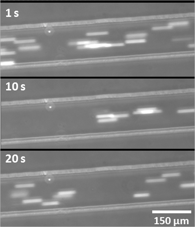 Laser fluence at the cell path is determined by measuring transmission of laser radiation through the cell suspension in the channel and also from reflection at the PDMS surface. Laser exposures were between 220 and 360 ms duration as that was the length of time for cells to transit the laser beam spot and was estimated from the flow velocity of a cell. Therefore, the output of the laser (irradiance in ) was adjusted to provide the indicated radiant exposure () during the time period of exposure. For post-exposure analyses, the initial cell suspension that passed through the channels with variable flow rate was collected and discarded continuously until a desired velocity was reached. Laser exposure was initiated only after a stable flow velocity was achieved. To remove the presence of remaining unexposed cells completely, laser exposure was continued on the cell suspension at the channel, treated/untreated cells were collected and discarded three times () from the collection wells. Viability of Jurkat-T cells following 2-μm laser irradiation in a microfluidic device was tested using calcein AM and EthD-1 viability staining kit. Equal volumes of stained cell suspension were taken in a 96-well microtiter plate for analysis. Grayscale images of stained Jurkat cells for two radiant exposures as seen under a fluorescent microscope are shown in Fig. 4. The cell viability analysis for different radiant exposure values is plotted in Fig. 5. The cell viability was scored after examining through the entire volume of 100-μl cell suspension in the well even though only a fraction of the examined cells throughout the volume is shown in Fig. 4. If at least half of the total cell population showed red staining, the population of cells was classified as not meeting the threshold for survival. In laser injury experiments, the threshold point ED-50 is cited as 50% probability of injury. Our experiments show that ED-50 for Jurkat cells is . This agrees well with recent data using this system to evaluate effects of red light on cell killing by 2-μm laser radiation.14 It should be noted that the damage threshold will be dependent on irradiance () only when photothermal damage mechanism is the dominating one.15 The same trend was observed in the current study as we used 2-μm laser that induces predominantly photothermal damage on the cells. Fig. 4Panels (a)–(h) show images of cells stained for viability after 2-μm laser exposure. Panels a, c, e, g show live cells (green fluorescence) and panels b, d, f, h show dead cells (red fluorescence). Corresponding live and dead images of each case are taken under the same imaging conditions. 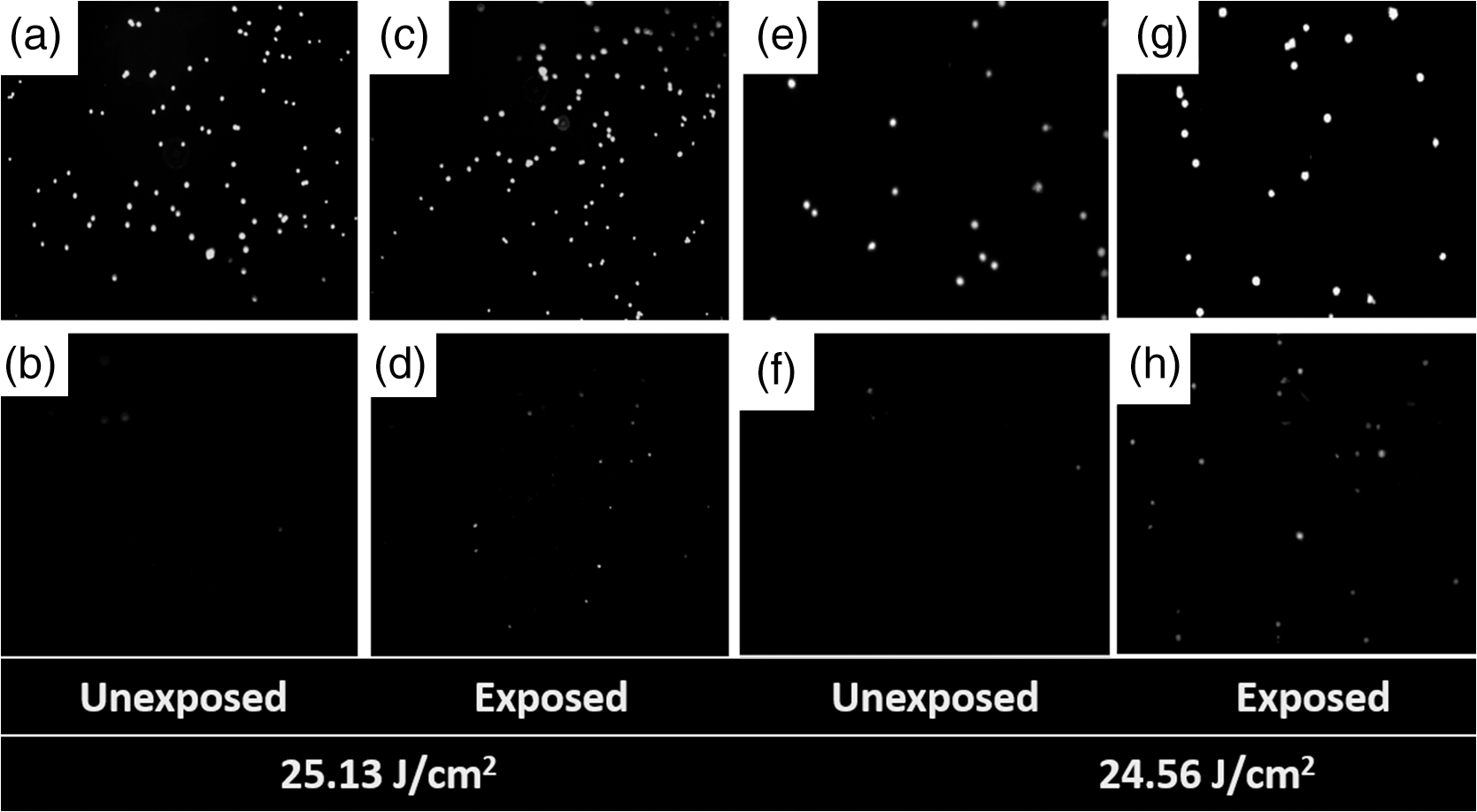 Fig. 5Cell survivability histogram of exposed Jurkat cells. Unexposed cells at all doses were determined to be alive.  Preliminary messenger ribonucleic acid (mRNA) analysis was conducted and expression levels of HSPA1A (a heat shock protein) are plotted in Fig. 6. Heat shock proteins (HSPs) were initially discovered as heat or cellular stress induced proteins. Over the last decade, research has concluded that HSPs play a role in cancer progression and the development of resistance to chemotherapeutic agents. HSPA1A is not normally present in significant amounts in nonstressed normal cells. It is upregulated in response to stress stimuli and promotes cell survival.16 HSPA1A is reported to promote survival of tumor cells through inhibition of apoptosis. HSP expression was not observed for laser fluences beyond . We suspect that the laser fluence was sufficiently high to induce necrotic rupture of the cells, thus no expression of HSPA1A. 4.ConclusionIn this paper, the development toward a microfluidic device which enables the delivery of continuous biological cell flux is presented. Steady flow rates of 2.5 to were achieved using 0.5 to of pumping rate. The cell viability analysis showed that cell survivability ceases above a laser exposure of , whereas little to no cell death was found in the control samples. Our preliminary results show a twofold increase in HSPA1A expression levels as the fluence approaches the laser damage threshold before the cells undergo necrosis. AcknowledgmentsThis work was financially supported by ASEE-SFFP program and an Air Force Office of Scientific Research (AFOSR) grant to J. C. W. Authors thank Lt. Brent Lavey, Mr. Larry Estlack, Mr. Kurt Schuster, and Mr. Corey Harbert for their technical assistance in accomplishing this project. Authors also thank Korean WCU project (R32-2009-000-20087-0). ReferencesM. A. MainsterT. J. WhiteR. G. Allen,
“Spectral dependence of retinal damage produced by intense light,”
J. Opt. Soc. Am., 60
(6), 848
–855
(1970). http://dx.doi.org/10.1364/JOSA.60.000848 JOSAAH 0030-3941 Google Scholar
J. T. Beckhamet al.,
“Assessment of cellular response to thermal laser injury through bioluminescence imaging of heat shock protein 70,”
Photochem. Photobiol., 79
(1), 76
–85
(2004). http://dx.doi.org/10.1111/j.1751-1097.2004.tb09860.x PHCBAP 0031-8655 Google Scholar
C. E. O’Connell-Rodwellet al.,
“A genetic reporter of thermal stress defines physiologic zones over a defined temperature range,”
FASEB J., 18
(2), 264
–271
(2004). http://dx.doi.org/10.1096/fj.03-0585com FAJOEC 0892-6638 Google Scholar
S. Wanget al.,
“HSP70 kinetics study by continuous observation of HSP-GFP fusion protein expression on a perfusion heating stage,”
Biotechnol. Bioeng., 99 146
–154
(2008). http://dx.doi.org/10.1002/(ISSN)1097-0290 BIBIAU 0006-3592 Google Scholar
G. J. Wilminket al.,
“Assessing laser-tissue damage with bioluminescent imaging,”
J. Biomed. Opt., 11
(4), 041114
(2006). http://dx.doi.org/10.1117/1.2339012 JBOPFO 1083-3668 Google Scholar
J. Komenet al.,
“Viabilty analysis and apoptosis induction of breast cancer cells in a microfluidic device:effect of cytostatic drugs,”
Biomed. Microdevices, 10
(5), 727
–737
(2008). http://dx.doi.org/10.1007/s10544-008-9184-5 BMICFC 1387-2176 Google Scholar
B. H. AnderssonA. van den Berg,
“Microtechnologies and nanotechnologies for single-cell analysis,”
Curr. Opin. Biotechnol., 15
(1), 44
–49
(2004). http://dx.doi.org/10.1016/j.copbio.2004.01.004 CUOBE3 0958-1669 Google Scholar
X. Fenget al.,
“Microfluidic chip: next-generation platform for systems biology,”
Anal. Chim. Acta, 650
(1), 83
–97
(2009). http://dx.doi.org/10.1016/j.aca.2009.04.051 ACACAM 0003-2670 Google Scholar
M. L. Dentonet al.,
“Damage thresholds for exposure NIR and blue lasers in an in vitro RPE cell system,”
Investig. Ophthalmol. Visual Sci., 47
(7), 3065
–3073
(2006). http://dx.doi.org/10.1167/iovs.05-1066 IOVSDA 0146-0404 Google Scholar
S. K. SiaG. M. Whitesides,
“Microfluidic devices fabricated in poly(dimethylsiloxane) for biological studies,”
Electrophoresis, 24
(21), 3563
–3576
(2003). http://dx.doi.org/10.1002/(ISSN)1522-2683 ELCTDN 0173-0835 Google Scholar
D.C. Duffyet al.,
“Rapid prototyping of microfluidic systems in poly(dimethylsiloxane),”
Anal. Chem., 70
(23), 4974
–4984
(1998). http://dx.doi.org/10.1021/ac980656z ANCHAM 0003-2700 Google Scholar
J. Wu, Thermofluid Engineering and Microsystems, The University of Tennessee, Knoxville, TN
(2008). Google Scholar
R. F. Marchington,
“Fluid flow at the micrometre scale,”
Applications of Microfluidic Chips in Optical Manipulation and Photoporation (Doctoral Dissertation), 41
–42 2010). Google Scholar
K.J. SchusterL.E. EstlackJ.C. Wigle,
“Exposing human retinal pigmented epithelial cells to red light in viro elicits an adaptive response to a subsequent 2-μm laser challenge,”
Proc. SPIE, 8569 856908
(2013). http://dx.doi.org/10.1117/12.2001646 PSISDG 0277-786X Google Scholar
M. L. Dentonet al.,
“In-vitro retinal model reveals a sharp transition between laser damage mechanisms,”
JBO Lett., 15
(3), 030512
(2010). http://dx.doi.org/10.1117/1.3449107 JBOPFO 1083-3668 Google Scholar
N. C. Dempsey-HibbertC. HoyleJ. H. H. Williams,
“Heat shock proteins in chronic lymphocytic leukaemia,”
Chronic Lymphocytic Leukemia, 399
–430 InTech, Rijeka, Croatia
(2012). Google Scholar
|