
|
|
1.IntroductionThermal therapy is gaining interest as a less invasive approach to tumor eradication compared to open surgery.1 The method aspires to destroy malignant tissues by means of a localized thermal effect without affecting the surrounding healthy environment. Various energy forms in different techniques have been investigated to create localized thermal sources generating temperatures between 41°C and 45°C for hyperthermia and for thermal ablation.2 Minimally invasive techniques use, for example, radio-frequency electric currents applied via needle electrodes to generate localized high temperatures to ablate liver and kidney tumors,3 or high intensity light via optical fibers in laser interstitial thermal therapy for the treatment of head and neck tumors.4 Of late, noninvasive thermal treatment is becoming a clinical possibility in the form of high intensity focused ultrasound (US),1 where high acoustic pressures are applied to cause precision thermal damage at the focal zone. A method which shows much potential in preclinical research settings is photothermal therapy. The technique relies on the use of laser light mediated by intense photoabsorbers passively or actively targeted to cancerous cells, to cause localized heating to selectively kill tumors.5 In order to ensure efficacy of the thermal therapy in destroying tumors while sparing normal tissue, it is crucial to monitor the temperature both spatially and temporally, while also imaging the region of interest to identify location and extent of the lesion. Physical temperature sensors, such as thermocouples, require minimally invasive placement at the target regions and are not desirable. Magnetic resonance (MR) imaging is noninvasive and can develop accurate temperature maps based on various temperature-sensitive tissue parameters such as proton resonance frequency and relaxation times.6 However, the cost of MR imaging limits widespread access to the technique. US imaging is inexpensive and noninvasive, with the ability to reliably quantify temperature rise based on the temperature dependence of backscattered power or pulse–echo time shift.7 However, the technique has poor lesion visualization and suffers from operator dependence and lack of standardization. The photoacoustic (PA) principle,8,9 which has the potential to image malignancies with high contrast,10,11 has been proposed to combine both imaging and temperature monitoring.12,13,14 The quantification of temperature rise is based on monitoring the PA signal amplitude, which changes due to the temperature dependence of the Grüneisen coefficient, a tissue parameter. The method, however, requires assumptions such as linear temperature dependence of the Grüneisen coefficient and invariance of the optical properties of the tissue under treatment that may be invalid. In this work, we use an approach based on speed-of-sound (SOS) tomography in a photoacoustic (CT) imager15 to image and monitor spatiotemporal evolution of temperature without recourse to the Grüneisen coefficient. We make use of the known temperature sensitivity of the SOS.16 In our method called “passive element” enriched PA CT, in a conventional PA imager, we placed passive absorbers with a small cross-section in the laser light path that illuminates the object under PA examination. These passive elements create laser-induced US, which propagates through the object allowing US transmission CT to be performed. Simultaneously, a large fraction of the incident light, which does not interact with the finite number of passive elements, illuminates the object permitting conventional PA CT. From the SOS tomograms, we derive two-dimensional (2-D) temperature maps estimated from the relationship between the temperature and the SOS of water. Proof-of-principle is demonstrated in a tissue-mimicking agar-based test object embedded with sodium alginate beads carrying gold nanospheres, with the imaging system modified to include a 532-nm continuous wave (CW) laser for the photothermal experiments. The experimental results were validated using Monte Carlo modeling of light propagation through a turbid medium, combined with heat diffusion modeling for spatial temperature distribution. 2.Materials and Methods2.1.Experimental SetupFigure 1 shows the schematic of the experiment in top and side view. A 532-nm Q-switched Nd:YAG laser, delivering 6-ns pulses with a 10-Hz repetition rate, was used for PA excitation to generate laser-induced US from the passive elements and PA signals in the test object. The pulse energy was 40 mJ with a beam diameter of 16 mm in a Gaussian beam profile. As passive elements, we used eight horsetail hairs with a diameter of 200 to 250 μm positioned in such a way that the object lies completely within the fanbeam traced by the line of sight from the passive element to the edge detector elements for all projections, as discussed in Ref. 15. The signal detected from the passive element of 200 to 250 μm is typically dominated by the detector center frequency and bandwidth. The test object, whose details are provided further, is mounted in a rotary stage and immersed in water in the imaging tank. The PA signals and US transmission signals are detected using a curvilinear array (Imasonic, Besançon, France) composed of 32 piezoelements (), with a central frequency of 6.25 MHz and 80% bandwidth. A 32-channel pulse-receiver system (Lecoeur Electronique, Chuelles, France) was used for data acquisition at a sampling rate of 80 MHz and 60 dB gain. With this system, 2-D PA tomograms can be developed with an in-plane resolution of 0.125 mm and an elevation resolution of 1.5 mm; SOS tomograms can be developed with an in-plane resolution of roughly 1 mm and elevation resolution of 5 mm.17 A 532-nm CW laser (Verdi V6) was used for photothermal excitation in the test object by illumination from beneath along the axis. Fig. 1A schematic of the setup using the passive-element approach. Pulsed laser light at 532 nm illuminates the fixed passive elements and a test object mounted on a rotary stage. Laser-induced ultrasound from the passive elements (horsetail hairs) and photoacoustic signals from the object are detected using a curvilinear array. A continuous wave (CW) laser (Verdi, 532 nm) photothermally heats the object from the bottom side ( direction).  2.2.Sample PreparationThe test object consisted of a cylinder with a diameter of 26 mm made out of 2% () agar and 3% () (dilution) of 20% stock Intralipid® with a tissue-mimicking reduced scattering coefficient () of and carrying three spherical sodium-alginate beads. The 4-mm-diameter beads were embedded in the imaging plane, positioned 5 mm away from the radial surface [Fig. 2(a)] and 10 mm distant from the CW illuminating at the bottom surface. Two of the alginate beads had different concentrations of 50-nm diameter gold nanospheres (AuNS)18 dispersed in them, while the third bead was a control with undiluted 20% stock Intralipid®. We used AuNS for this first study in preference to the more popular gold nanorods (AuNR) since spheres are simpler to synthesize, are not susceptible to pulsed laser-induced optical property changes, and do not require special treatments.18 Figure 2(a) shows the photograph of the object with the beads still visible during the fabrication of the test object. Figure 2(b) shows the optical absorption spectrum obtained from suspensions of AuNS at concentrations and (particles/ml) leading, respectively, to absorption coefficients () of 2.5 and at 532 nm. Fig. 2(a) Photograph of top-view of the agar test object during fabrication showing the three alginate beads. Two of these beads contain different concentrations ( and ) of gold nanospheres (AuNS) and the third bead was made from 20% stock Intralipid. (b) Absorption spectra of the used AuNS concentrations, (c) photoacoustic slice image shows the two absorbing beads with different contrasts, (d) the speed-of-sound (SOS) image shows the bead with Intralipid having a lower sound velocity than agar. The alginate beads with AuNS are not visualized. 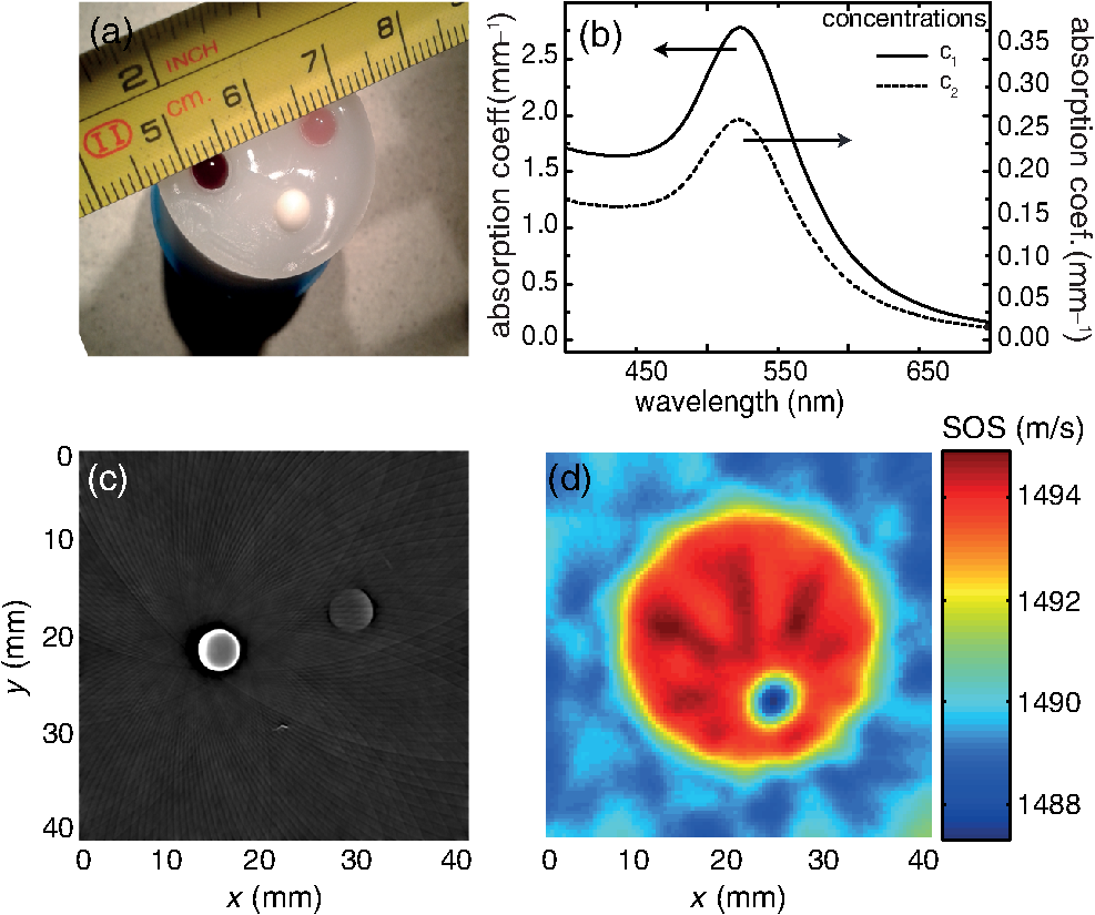 2.3.Measurement and Reconstruction ProceduresThe experiments were performed at a room temperature of 25°C. A reference measurement is first made of the time-of-flight (TOF) of the passive element signals through water without the object. When the object is introduced, 10 projections around 360 deg are acquired, with 10 averages per projection: data for one 2-D image is acquired every 30 s. The object is imaged before CW illumination, and the PA and SOS maps are reconstructed off-line. The PA map is reconstructed using filtered backprojection. For the SOS images, the integrated TOF measurements are estimated when the sample is present for every passive element, at every detector element and every view. This is obtained by first calculating a reference template signal by averaging the received passive element signals of the reference measurement in water from all detection elements. Using a matched filter, the passive element signals of the object at each element for every view are correlated with the reference template. This results in TOF values, accurate up to the sampling period of the time signal, which gives an initial guess of TOF. Subsequently, we obtain subsample accuracy using a maximum likelihood estimator discussed in Ref. 19. From the TOF data, the SOS map is reconstructed using a ray-driven discretized measurement model. This is discussed in detail in Refs. 17 and 19. We then performed photothermal heating of the AuNS-embedded beads by irradiating the object from below using the CW beam expanded to a diameter of 1 cm. The sequence is as follows: the injected power is increased from 1 to 3.3 W in steps of 0.5 W at intervals of 6 min except for the last increase, which was around 0.8 W; the power is then lowered to 1.5 W for 11 min, after which the illumination is switched off. The heating and cooling down sequence is completed within 40 min. Meanwhile, we continuously performed hybrid imaging of PA and SOS. The SOS tomogram images are converted to temperature maps using the relationship between SOS in water and temperature,20 which is a valid first approximation since the objects and beads are composed of 98% water. 2.4.ModelingTo support the experimental results, we modeled the experimental situation to verify the observed temperature evolution. Monte Carlo simulation21 was first used to estimate the absorbed energy at each bead position. The known optical properties of the object were used in the model, with the beads having a 4-mm diameter, positioned 10-mm deep from the illuminating surface. To reproduce the illumination conditions of the experiment, we have modified the illumination profile from the point source to a Gaussian profile by using inverse cumulative distribution function, which provides a photon injection position with a Gaussian probability distribution. The increase of irradiating power over time was described using a piecewise polynomial. The obtained absorbed energy density over time is then included as source in the heat-diffusion equation: where represents the temperature distribution, the specific heat capacity, is mass density, and is the thermal conductivity, while is the heating source corresponding to the absorbed energy density. The three-dimensional equation was solved numerically using Mathematica with Dirichlet boundary conditions, using the thermal properties and density of water.3.Results3.1.PA and SOS ImagingThe US and PA images of the phantom are presented in Fig. 2. In the PA map of the object [Fig. 2(c)], we see the presence of two spheres with different contrasts, due to the difference in AuNS concentrations. The third sphere is not visible since it does not contain any absorbers. The SOS map [Fig. 2(d)], however, clearly shows the third bead with lower SOS than the surrounding area; the contrast arises due to the higher concentration of lipids in the bead than in agar. The other inclusions are not visible, suggesting that the used AuNS concentrations have few effects on the SOS. The differences in SOS between agar and water are also clearly visible. 3.2.Temperature MonitoringFigures 3(a) and 3(b) represent the SOS maps covering at two different power levels. The images show the presence of confined SOS increase at the locations of the AuNS-embedded beads, whereas the SOS of the control bead and the surrounding agar remains unchanged. The SOS changes are due to the temperature rise in the beads and their immediate vicinity due to the photothermal heating and heat diffusion. The SOS maps are converted into temperature maps after subtracting the reference image before irradiation. Figure 3(c) shows a graph of the temperature increase sampled at three different locations in the temperature maps: the center of the bead, the center of the bead, and the center of the test object. A progressively step-wise increase in temperature is observed at the beads that follows the sequence of increasing optical power delivered. Within each step, a sharp rise in temperature is observed before a slow down to saturation after a few minutes of irradiation. This saturation is a consequence of the competition between the accumulated absorbed energy in the bead and heat diffusion to the surrounding medium. During the temperature increase sequence, the center of the object shows a 3°C increase due to heat diffusion from beads. When the optical power is reduced to 1.5 W, the temperatures at all locations drop to the same level observed during the rising sequence. When the laser is switched off, the temperatures return toward the initial baseline values. Fig. 3(a) and (b) SOS maps at two different levels of irradiation, (c) temperature evolution at three locations in the temperature maps estimated from the SOS tomograms: at center of bead with AuNS concentration (), at center of bead with concentration (), and at center of test object. The continuous (red) lines are obtained from simulation combining Monte Carlo and the heat diffusion equation.  Modeling was done based on a combination of Monte Carlo simulations for light propagation and absorption and solving of the heat diffusion equation for thermal propagation from the sites of optical absorption. The results are shown in Fig. 3(c) (red curves): we observe that the simulated temperature evolution corresponds well with the experiment for the bead with lower concentration. The experimentally derived temperatures for the bead with higher concentration are slightly lower than in the simulation, especially at higher powers. The deviations may be due to the inaccuracies in defining parameters related to illumination conditions, optical and thermal properties of the object and beads, and the exact depth. A faster temperature increase is also observed in the simulation compared to experiment. This is likely due to the experimentally slow acquisition time compared to the simulation. 4.Discussion and ConclusionWe have demonstrated acquisition of temperature maps via SOS images while simultaneously performing PA imaging without the requirement for additional measurements or instruments. The method is based on the multiple passive element enriched PA CT approach, which can achieve hybrid imaging of PA and SOS tomograms. Since the method uses externally generated US to interrogate the temperature-dependent SOS of the region-of-interest (ROI), it is robust, in contrast with PA methods that use signal intensities from the ROI itself as a measure of the temperature via the Grüneisen coefficient. In these latter methods, it cannot be excluded that the optical properties of the ROI change during the treatment, therefore affecting the accuracy of temperature estimation. Furthermore, no calibration procedures are required in our approach in contrast with the previously presented Gruneisen coefficient–dependent methods. There is an advantage over US CT, which can also image SOS and temperature,16 since the PA part of our approach also permits visualization of lesions with high contrast.10 Finally, our method allows for the measurement of temperature profiles deep inside highly scattering media with good spatial resolution, while commonly available thermal imaging techniques that use infrared cameras can only measure superficial temperatures with accuracy due to the limited penetration of infrared energy in water-rich tissues. Although the method is not restricted to photothermal treatments, being applicable to all other thermal therapies, it does have the ability to be able to locate photoabsorbers used in the light-based methods. However, there is yet much room for improvement: in the current implementation, acquisition of a SOS and temperature tomogram requires 30 s. Faster imaging can be realized by adding more passive elements to minimize the minimum required number of views around the object.22 Although the proof-of-principle on a test object using 2-D imaging has been demonstrated here, the most important step remains systematic in vivo evaluation of the approach. However, certain issues still need to be investigated before moving toward in vivo measurements. An important aspect is the temperature dependence of SOS on tissue type. A further complication in this respect is that the acoustic velocity change with temperature in lipid-rich tissue is opposite in direction compared to water-rich tissues. Thorough investigations are required to measure these variations in various reference tissues. The availability of such a knowledgebase of SOS behaviors combined with the ability of the PA imaging modality of our technique to identify various tissue types may help to improve the robustness and accuracy of the temperature estimation in vivo. Another aspect is the acoustic attenuation; for the proposed experiments, this effect is negligible since the phantom was made from 98% of water and thickness. However, this may affect the accuracy of the estimation in real-tissue measurements and should therefore be taken into account. The passive element technique also allows, besides SOS mapping, recovering the acoustic attenuation inside the object,18 and this information will be used to correct for PA imaging, especially in highly attenuating media.23 For higher temperatures in excess of 55°C, protein coagulation will also occur, which may have complex effects on the SOS making the estimation of temperature by our method inaccurate. For use of the method in this situation, the relationship between SOS and temperature during coagulation should be investigated. Since our method allows hybrid imaging, as mentioned earlier, we can use PAs to monitor changes in tissue optical properties caused by coagulation24,25 and then use the SOS–temperature relations that apply in this regime. Finally, from the perspective of preclinical and clinical measurements, the proposed method is suited for objects, which lend themselves to the acquisition of multiple PA projections in a tomographic geometry. The logical application of the method will thus be in investigations in small animals such as mouse models of disease. In the clinic, imaging of the breast pendant in water as coupling medium is the most suitable application. An implementation can take the form of the preclinical designs allowing three-dimensional PA and ultrasound transmission imaging presented by Ermilov et al.22 Anis et al.,26 and Wurzinger et al.27 AcknowledgmentsFinancial support from the Technology Foundation in the Netherlands (STW) under Vici-grant 10831; by Agentschap NL under Eureka grant E!4993; Netherlands Organization for Health Research and Development (ZonMw) under the program New Medical Devices for Affordable Health; and RAPACT High-Tech Health Farm (OCRI). ReferencesJ. E. Kennedy,
“High-intensity focused ultrasound in the treatment of solid tumours,”
Nat. Rev. Cancer, 5
(4), 321
–327
(2005). http://dx.doi.org/10.1038/nrc1591 NRCAC4 1474-175X Google Scholar
S. S. MambulaS. K. Calderwood,
“Heat induced release of Hsp70 from prostate carcinoma cells involves both active secretion and passive release from necrotic cells,”
Int. J. Hyperther., 22
(7), 575
–585
(2006). http://dx.doi.org/10.1080/02656730600976042 IJHYEQ 0265-6736 Google Scholar
S. N. Goldberg,
“Radiofrequency tumor ablation: principles and techniques,”
Eur. J. Ultrasound, 13
(2), 129
–147
(2001). http://dx.doi.org/10.1016/S0929-8266(01)00126-4 0929-8266 Google Scholar
J. Feyhet al.,
“MRI-guided laser interstitial thermal therapy (LITT) of head and neck tumors: progress with a new method,”
J. Clin. Laser Med. Surg., 14
(6), 361
–366
(1996). Google Scholar
L. R. Hirschet al.,
“Nanoshell-mediated near-infrared thermal therapy of tumors under magnetic resonance guidance,”
Proc. Natl. Acad. Sci. U. S. A., 100
(23), 13549
–13554
(2003). http://dx.doi.org/10.1073/pnas.2232479100 PNASA6 0027-8424 Google Scholar
J. De Poorteret al.,
“Noninvasive MRI thermometry with the proton resonance frequency (PRF) method: in vivo results in human muscle,”
Magn. Reson. Med., 33
(1), 74
–81
(1995). http://dx.doi.org/10.1002/(ISSN)1522-2594 MRMEEN 0740-3194 Google Scholar
R. M. Arthuret al.,
“Non-invasive estimation of hyperthermia temperatures with ultrasound,”
Int. J. Hyperther., 21
(6), 589
–600
(2005). http://dx.doi.org/10.1080/02656730500159103 IJHYEQ 0265-6736 Google Scholar
C. LutzweilerD. Razansky,
“Optoacoustic imaging and tomography: reconstruction approaches and outstanding challenges in image performance and quantification,”
Sensors (Basel), 13
(6), 7345
–7384
(2013). http://dx.doi.org/10.3390/s130607345 SNSRES 0746-9462 Google Scholar
L. H. V. WangS. Hu,
“Photoacoustic tomography: in vivo imaging from organelles to organs,”
Science, 335
(6075), 1458
–1462
(2012). http://dx.doi.org/10.1126/science.1216210 SCIEAS 0036-8075 Google Scholar
M. Heijblomet al.,
“Visualizing breast cancer using the Twente photoacoustic mammoscope: what do we learn from twelve new patient measurements?,”
Opt. Express, 20
(11), 11582
–11597
(2012). http://dx.doi.org/10.1364/OE.20.011582 OPEXFF 1094-4087 Google Scholar
S. A. Ermilovet al.,
“Laser optoacoustic imaging system for detection of breast cancer,”
J. Biomed. Opt., 14
(2), 024007
(2009). http://dx.doi.org/10.1117/1.3086616 JBOPFO 1083-3668 Google Scholar
G. Schuleet al.,
“Noninvasive optoacoustic temperature determination at the fundus of the eye during laser irradiation,”
J. Biomed. Opt., 9
(1), 173
–179
(2004). http://dx.doi.org/10.1117/1.1627338 JBOPFO 1083-3668 Google Scholar
J. Shahet al.,
“Photoacoustic imaging and temperature measurement for photothermal cancer therapy,”
J. Biomed. Opt., 13
(3), 034024
(2008). http://dx.doi.org/10.1117/1.2940362 JBOPFO 1083-3668 Google Scholar
E. Petrovaet al.,
“Using optoacoustic imaging for measuring the temperature dependence of Grüneisen parameter in optically absorbing solutions,”
Opt. Express, 21 25077
–25090
(2013). Google Scholar
S. Resinket al.,
“Multiple passive element enriched photoacoustic computed tomography,”
Opt. Lett., 36
(15), 2809
–2811
(2011). http://dx.doi.org/10.1364/OL.36.002809 OPLEDP 0146-9592 Google Scholar
S. A. Johnsonet al.,
“Non-intrusive measurement of microwave and ultrasound-induced hyperthermia by acoustic temperature tomography,”
977
–982
(1977). Google Scholar
J. Joseet al.,
“Speed-of-sound compensated photoacoustic tomography for accurate imaging,”
Med. Phys., 39
(12), 7262
–7271
(2012). http://dx.doi.org/10.1118/1.4764911 MPHYA6 0094-2405 Google Scholar
S. ManoharC. UngureanuT. G. Van Leeuwen,
“Gold nanorods as molecular contrast agents in photoacoustic imaging: the promises and the caveats,”
Contrast Media Mol. I, 6
(5), 389
–400
(2011). http://dx.doi.org/10.1002/cmmi.454 CMMICO 1555-4309 Google Scholar
J. Joseet al.,
“Passive element enriched photoacoustic computed tomography (PER PACT) for simultaneous imaging of acoustic propagation properties and light absorption,”
Opt. Express, 19
(3), 2093
–2104
(2011). http://dx.doi.org/10.1364/OE.19.002093 OPEXFF 1094-4087 Google Scholar
W. Marczak,
“Water as a standard in the measurements of speed of sound in liquids,”
J. Acoust. Soc. Am., 102
(5), 2776
–2779
(1997). http://dx.doi.org/10.1121/1.420332 JASMAN 0001-4966 Google Scholar
L. WangS. L. JacquesL. Zheng,
“MCML—Monte Carlo modeling of light transport in multi-layered tissues,”
Comput. Methods Programs Biomed., 47
(2), 131
–146
(1995). http://dx.doi.org/10.1016/0169-2607(95)01640-F CMPBEK 0169-2607 Google Scholar
S. A. Ermilovet al.,
“3D laser optoacoustic ultrasonic imaging system for preclinical research,”
Proc. SPIE, 8581 85810N
(2013). http://dx.doi.org/10.1117/12.2008811 PSISDG 0277-786X Google Scholar
C. Huanget al.,
“Photoacoustic computed tomography correcting for heterogeneity and attenuation,”
J. Biomed. Opt., 17
(6), 061211
(2012). http://dx.doi.org/10.1117/1.JBO.17.6.061211 JBOPFO 1083-3668 Google Scholar
K. V. LarinI. V. LarinaR. O. Esenaliev,
“Monitoring of tissue coagulation during thermotherapy using optoacoustic technique,”
J. Phys. D Appl. Phys., 38
(15), 2645
–2653
(2005). http://dx.doi.org/10.1088/0022-3727/38/15/017 JPAPBE 0022-3727 Google Scholar
Y. S. HsiaoX. D. WangC. X. Deng,
“Dual-wavelength photoacoustic technique for monitoring tissue status during thermal treatments,”
J. Biomed. Opt., 18
(6), 067003
(2013). http://dx.doi.org/10.1117/1.JBO.18.6.067003 JBOPFO 1083-3668 Google Scholar
F. Aniset al.,
“Image reconstruction and system optimization for three-dimensional speed of sound tomography using laser-induced ultrasound,”
Proc. SPIE, 8581 85814T
(2013). http://dx.doi.org/10.1117/12.2008813 PSISDG 0277-786X Google Scholar
G. Wurzingeret al.,
“Simultaneous three-dimensional photoacoustic and laser-ultrasound tomography,”
Biomed. Opt. Express, 4
(8), 1380
–1389
(2013). http://dx.doi.org/10.1364/BOE.4.001380 BOEICL 2156-7085 Google Scholar
|


