
|
|
1.IntroductionPhotoacoustic tomography (PAT) provides high-resolution biomedical images beyond the optical diffusion limit by combining optical absorption contrast and ultrasonic spatial resolution.1 To obtain high-quality images, specialized full-ring transducer arrays2,3 are used for full-view detection, but they are more expensive than linear arrays and cannot be easily integrated with ultrasound systems. While commercial linear arrays are readily available, they often suffer from limited-view problems,4 and the detectable structure highly depends on the orientations and positions of the probes.5 To overcome this problem, many methods have been proposed. For instance, both Yang et al.6 and Gateau et al.7 circularly or semicircularly scanned a linear array to achieve full-view or half-view PAT. However, these methods require time-consuming mechanical scanning. Wu et al.8 proposed to use speckle noise to derive PAT. This method requires solution of Green’s function and was demonstrated only in simulations. Another method is to utilize artificial backscatters as virtual transducers.9 However, their system is still based on circular scanning with a single-element transducer, and modeling the backscattered signals is complicated. Limited-view problems can also be ameliorated by advanced reconstruction algorithms; however, they are normally computationally intensive and time-consuming.10–12 In addition, Cox et al.13 proposed to use acoustic reflectors at either end of, and perpendicular to, an array to generate an infinitely wide virtual array, but this method was also demonstrated only in simulations. In this letter, we propose a simple and direct approach to double the detection view of a linear array photoacoustic (PA) imaging system. Our method utilizes a 45-deg acoustic reflector to form a virtual array, whose signals are used in image reconstruction to overcome the limited-view problem.14 2.Experimental Setup and ResultsFigure 1 shows the experimental setup in a water tank in top view. Compared to conventional linear array imaging systems, a quarter-inch thick borosilicate glass plate (8476K72, McMaster-Carr, Los Angeles, California) was added as the acoustic reflector to form a virtual array. The glass plate has a sound speed of for longitudinal waves and for shear waves. When the angle of incidence is (the critical angle for Rayleigh surface waves), the incident PA waves will be completely reflected without distortion. For angles of incidence between 0 deg (normal incidence) and a longitudinal critical angle of 14 deg, of the incident pressure will be reflected with no phase change,14 but it will have multiple delayed reflections due to reverberation. Reflection for the angular range between 14 and 26 deg is even more complicated by amplitude and phase changes with the angle. Here, however, we did not take it into account in reconstruction. This problem can be overcome by using a reflector made of a material with a higher shear modulus, such as sapphire, in which the critical angle for Rayleigh surface waves can be as small as 12 deg. Fig. 1Top view of the experimental setup. RB, reflected beam; RE, physical receiving element; RE’, virtual receiving element. The commercial Philips array operated in B-mode to collect photoacoustic signals, a 45-deg acoustic reflector (glass) formed a virtual array, and a laser illuminated light orthogonally to the drawing from the top (not shown in the figure). 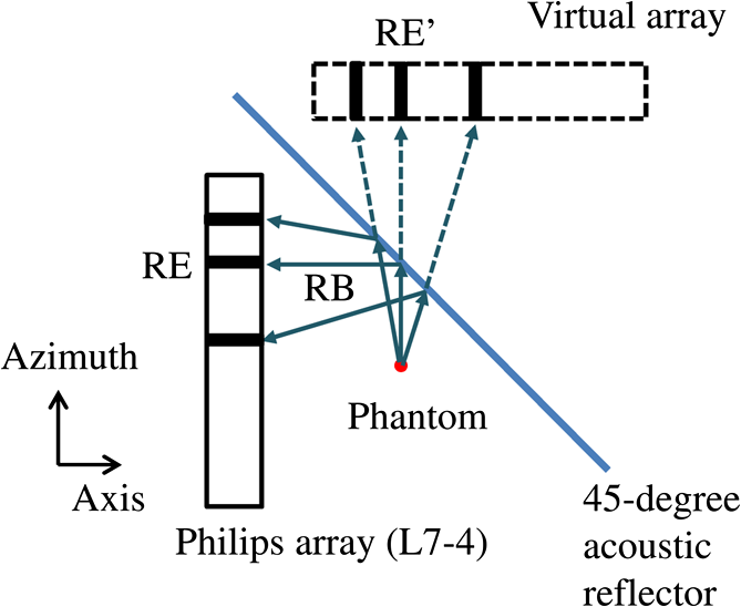 As illustrated in Fig. 1, some PA waves will be reflected by the acoustic reflector and detected by receiving elements (RE) of the physical array. According to the method of image that is used to satisfy the boundary condition imposed by the reflector, the same waves can be considered being detected by the elements of a virtual array situated in an acoustic homogeneous medium without the reflector.14 Therefore, the system functionally consists of two linear arrays that are perpendicular to each other. The linear array (L7-4, Philips Healthcare, Andover, Massachusetts) has 128 elements with a center frequency of 5.0 MHz, a receiving bandwidth of , a pitch of 0.3 mm, and an elevational height of 6 mm. It is cylindrically focused in the elevation, with a focal length of 25 mm. The PA signals received by the array were multiplexed and digitalized by a 64-channel commercial ultrasound system (V-1, Verasonics Inc., Redmond, Washington) with a sampling rate of 60 MHz. The hard boundary condition formed by the reflector was satisfied by directly assigning the received PA signals to the virtual array.14 The image was then reconstructed using the conventional filtered back-projection algorithm for an infinite medium without boundaries. To increase the signal-to-noise ratio, each image was averaged by 64 times, so it took to acquire an image. For simplicity, top illumination was provided by a Q-switched Nd:YAG laser (LS-2137/2, LOTIS TII, Minsk, Belarus) with a pulse duration and a pulse repetition rate of 10 Hz. The 532-nm laser light was homogenized by an optical diffuser (EDC-5, RPC Photonics, Rochester, New York), and the incident laser beam on the phantom/tissue surface was controlled to be less than the maximum permissible exposure set by the American National Standards Institute ().15 During experiment, we used a 45-deg angle ruler to align the array and the reflector. During reconstruction, we numerically adjusted the position of the virtual array for the sharpest image. The axial, lateral, and elevational resolutions of the system were , 0.3, and 1.6 mm, respectively, found by measuring the point spread function from the cross-sectional images of human hairs. To experimentally validate the proposed technique, we imaged a phantom consisting of four human hairs at different angles on the azimuth-axis plane [Fig. 2(a)] and reconstructed the image under different conditions. Figure 2(b) is an image acquired without the presence of the acoustic reflector. Figure 2(c) is an image acquired with the presence of the reflector—as indicated by the dashed line—but reconstructed without incorporating the virtual array. From these two images, we can see that the linear array cannot detect the horizontal hair because the cylindrical PA wavefront from that hair propagates in the azimuth (vertical) direction and hence misses the physical array unless it is bounced by the reflector. By contrast, the reconstruction incorporating data from the virtual array successfully overcomes this problem [Fig. 2(d)] and all the hairs can be visualized. While the vertical hair is imaged directly by the physical array, the horizontal one is imaged by the virtual array. However, because of the limited acceptance angle of the array, the hairs at [marked with solid arrows in Figs. 2(b) to 2(d)] appear blurrier and weaker than the two orthogonal hairs. Based on the Field II ultrasound simulation program,16 the acceptance angle (3 dB drop in one-way pressure profile at the distance of the elevational focus) of each element in the array is . Therefore, PA signals traveling at a 45-deg angle of incidence from the hair are less detectable by the array. For simplicity, only the real images are shown in the rest of the figures. Fig. 2Photoacoustic tomography (PAT) images of a hair phantom. (a) Diagram of the hair phantom; the gray rectangle indicates the approximate field of view. (b) Image of the hair phantom acquired without the presence of the acoustic reflector. (c) Image of the phantom acquired with the presence of the reflector but reconstructed without incorporating data from the virtual array. (d) Image of the phantom acquired with the presence of the reflector and reconstructed with data from the virtual array incorporated. The dashed line indicates the position of the acoustic reflector.  A more complicated phantom, consisting of a leaf skeleton embedded in agar [Fig. 3(a)], was also used to experimentally validate the proposed method. Agar has acoustic properties similar to those of the coupling water. Figures 3(b) to 3(d) show two-dimensional (2-D) images acquired and reconstructed under different conditions. Figure 3(b) is an image acquired without the presence of the reflector, and Fig. 3(c) is an image acquired with the presence of the acoustic reflector but reconstructed without incorporating the virtual array. In both images, the major skeletons on the lower-right side of the leaf were missing due to limited view. By incorporating the virtual array, those missing skeletons were clearly recovered, as indicated by the arrows in Fig. 3(d). The major skeleton of 45-deg orientation [marked with solid arrows in Figs. 3(b) to 3(c)] is more blurred, maybe due to the limited acceptance angle of the array. The streaking artifacts in Fig. 3(d) (indicated by white dashed arrows) may be attributed to insufficient view angle coverage. Fig. 3PAT images of a leaf skeleton phantom. (a) Photo of the phantom. (b) Image of the leaf skeleton phantom acquired without the presence of the acoustic reflector. (c) Image of the phantom acquired with the presence of the reflector but reconstructed without incorporating data from the virtual array. (d) Image of the phantom acquired with the presence of the acoustic reflector and reconstructed with data from the virtual array incorporated.  The efficacy of the proposed method was also evaluated by imaging an ear of an euthanatized C57BL/6 mouse (Fig. 4). The mouse ear was supported by an agar cylinder to make it as flat as possible in the azimuth-axis plane. The center of the ear was located approximately at the elevational focus of the array. Because of the strong blood absorption at 532 nm, major vasculature across the ear is visible. Again, without considering the virtual array, the presence of the acoustic reflector barely changes the 2-D images [Fig. 4(b) versus Fig. 4(c)], where two major vessels at small angles to the axial direction are missing due to limited view. When the reconstruction includes data from the virtual array, these two vessels can be visualized, as indicated by arrows in Fig. 4(d). The advantages of the acoustic reflector and the increased detection view are well demonstrated in this ex vivo experiment. The small vertical artifacts in Figs. 4(b) to 4(c) may be caused by streaking artifacts from insufficient views of small structures (such as tiny hairs, melanin, and small vessels) on the mouse ear. Similar artifacts appear horizontal when the virtual array is incorporated in the reconstruction [Fig. 4(d)]. Also, the curvature of the mouse ear may have caused some blurring artifacts. Fig. 4Ex vivo PAT images of a mouse ear. (a) Photo of the mouse ear. (b) Image of the mouse ear acquired without the presence of the acoustic reflector. (c) Image of the mouse ear acquired with the presence of the reflector but reconstructed without incorporating data from the virtual array. (d) Image of the mouse ear acquired with the presence of the acoustic reflector and reconstructed with data from the virtual array incorporated. 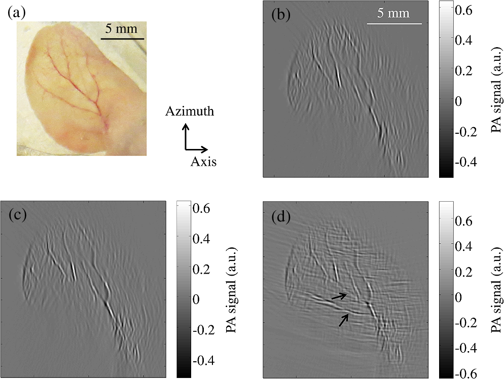 3.Discussion and SummaryBy using an acoustic reflector, we successfully doubled the detection view of a linear array PAT system. The concept is widely applicable to other commercial arrays. Even though the same effect can be achieved by shifting and rotating (by 90 deg) the physical array, our approach has distinct advantages. First, our system does not require any mechanical scanning, shortening the imaging time. Second, the reflector is optically transparent, thereby allowing more flexible light illumination schemes. While a 45-deg reflector was utilized in the study, the array and acoustic reflector orientations can be flexibly designed for other applications. The current setup did not achieve a detection angle because each element in the array has a divergence angle of . This problem can be eliminated by using either an array with a larger acceptance angle or multiple reflectors. Our method is designed initially for small animal imaging. The acoustic reflector can be implemented as the boundary of the immersion tank. In this case, the real and virtual arrays will form a half-enclosed space for the object, which should improve the image quality substantially. For very large objects, we can translate the array one or multiple steps in the azimuthal direction with a step size equal to the length of the array, and the imaging region will be enlarged accordingly. In summary, both phantom and ex vivo images demonstrate that the acoustic reflector provides a simple and easy approach to increase the detection view of linear-array-based PAT, yielding higher-quality PA images. AcknowledgmentsThe authors would like to thank Professor Ballard James for reading the manuscript. The authors would also like to thank Dr. Mohammadreza Nasiriavanaki, Mr. Guo Li, and Mr. Wenxin Xing for useful discussions and experimental assistance. This work was sponsored in part by the National Institutes of Health grants DP1 EB016986 (NIH Director’s Pioneer Award), R01 EB016963, R01 EB008085, R01 CA134539, U54 CA136398, R01 EB010049, R01 CA157277, and R01 CA159959. L. W. has a financial interest in Microphotoacoustics Inc. and Endra Inc., and K. M. has a financial interest in Microphotoacoustics Inc., neither of which supported this work. ReferencesL. V. Wang,
“Multiscale photoacoustic microscopy and computed tomography,”
Nat. Photonics, 3
(9), 503
–509
(2009). http://dx.doi.org/10.1038/nphoton.2009.157 1749-4885 Google Scholar
J. Xiaet al.,
“Three-dimensional photoacoustic tomography based on the focal-line concept,”
J. Biomed. Opt., 16
(9), 090505
(2011). http://dx.doi.org/10.1117/1.3625576 JBOPFO 1083-3668 Google Scholar
J. Xiaet al.,
“Whole-body ring-shaped confocal photoacoustic computed tomography of small animals in vivo,”
J. Biomed. Opt., 17
(5), 050506
(2012). http://dx.doi.org/10.1117/1.JBO.17.5.050506 JBOPFO 1083-3668 Google Scholar
Y. Xuet al.,
“Reconstructions in limited-view thermoacoustic tomography,”
Med. Phys., 31
(4), 724
–733
(2004). http://dx.doi.org/10.1118/1.1644531 MPHYA6 0094-2405 Google Scholar
S. Preisseret al.,
“Vessel orientation-dependent sensitivity of optoacoustic imaging using a linear array transducer,”
J. Biomed. Opt., 18
(2), 026011
(2013). http://dx.doi.org/10.1117/1.JBO.18.2.026011 JBOPFO 1083-3668 Google Scholar
D. W. Yanget al.,
“Fast full-view photoacoustic imaging by combined scanning with a linear transducer array,”
Opt. Express, 15
(23), 15566
–15575
(2007). http://dx.doi.org/10.1364/OE.15.015566 OPEXFF 1094-4087 Google Scholar
J. Gateauet al.,
“Three-dimensional optoacoustic tomography using a conventional ultrasound linear detector array: whole-body tomographic system for small animals,”
Med. Phys., 40
(1), 013302
–013311
(2013). http://dx.doi.org/10.1118/1.4770292 MPHYA6 0094-2405 Google Scholar
D. WuC. TaoX. Liu,
“Photoacoustic tomography extracted from speckle noise in acoustically inhomogeneous tissue,”
Opt. Express, 21
(15), 18061
–18067
(2013). http://dx.doi.org/10.1364/OE.21.018061 OPEXFF 1094-4087 Google Scholar
D. Wuet al.,
“Limited-view photoacoustic tomography utilizing backscatterers as virtual transducers,”
Appl. Phys. Lett., 99
(24), 244102
–244103
(2011). http://dx.doi.org/10.1063/1.3669512 APPLAB 0003-6951 Google Scholar
L. NieD. XingS. Yang,
“In vivo detection and imaging of low-density foreign body with microwave-induced thermoacoustic tomography,”
Med. Phys., 36
(8), 3429
–3437
(2009). http://dx.doi.org/10.1118/1.3157204 MPHYA6 0094-2405 Google Scholar
L. Nieet al.,
“Thermoacoustic molecular tomography with magnetic nanoparticle contrast agents for targeted tumor detection,”
Med. Phys., 37
(8), 4193
–4200
(2010). http://dx.doi.org/10.1118/1.3466696 MPHYA6 0094-2405 Google Scholar
S. MaS. YangH. Guo,
“Limited-view photoacoustic imaging based on linear-array detection and filtered mean-backprojection-iterative reconstruction,”
J. Appl. Phys., 106
(12), 123104
–123106
(2009). http://dx.doi.org/10.1063/1.3273322 JAPIAU 0021-8979 Google Scholar
B. T. CoxS. R. ArridgeP. C. Beard,
“Photoacoustic tomography with a limited-aperture planar sensor and a reverberant cavity,”
Inverse Probl., 23
(6), S95
(2007). http://dx.doi.org/10.1088/0266-5611/23/6/S08 INPEEY 0266-5611 Google Scholar
L. V. WangX. Yang,
“Boundary conditions in photoacoustic tomography and image reconstruction,”
J. Biomed. Opt., 12
(1), 014027
(2007). http://dx.doi.org/10.1117/1.2709861 JBOPFO 1083-3668 Google Scholar
American National Standard for Safe Use of Lasers ANSI Z136.1-2000, Laser Institute of America, American National Standards Institute Inc., New York, NY
(2000). Google Scholar
J. A. Jensen,
“FIELD: a program for simulating ultrasound systems,”
Med. Biol. Eng. Comput., 34
(Suppl 1), 351
–353
(1996). http://dx.doi.org/10.1007/BF02520003 MBECDY 0140-0118 Google Scholar
|


