
|
|
1.IntroductionIn the last decade, considerable attention has been given to the investigation of biological tissue by using novel photonic-based imaging and diagnostic modalities.1 Optical techniques offer a strong advantage given that diagnostic procedures can be performed noninvasively on biotissues in situ. Optical diagnostic systems illuminate biological tissues with UV, visible, or infrared light and attempt to analyze the resulting reflectance, fluorescence emission, or Raman spectra.2 Recently, for the same purpose, the polarization of light scattered in biological tissues has gained much attention.3 Various aspects of polarized light scattered in tissues as well as in other tissue-like scattering media have been extensively studied in the past.3–6 Nevertheless, the development and practical implementation of polarization-based optical systems for day-to-day diagnostic routines, as well as interpretation and quantitative analysis of the experimental results, require an accurate description of polarized light propagation in biological tissues. Due to the complex structure of biological tissues and high scattering of light therein, the analytical approaches describing radiative transfer are impractical and cannot be applied. Stochastic alternatives, such as Monte Carlo (MC) methods,7 are ideally suited for modeling of optical radiation propagation in complex scattering media. The conventional MC approach is comprehensively described elsewhere (see, e.g., Refs. 8 and 9), and is based on the modeling of energy or intensity transfer through the medium. It does not take into account the wave nature of light, i.e., polarization, coherence, phase retardation, interference, and associated wave phenomena. Recently, a new generation of stochastic MC techniques has been developed and widely employed in the studies of coherent effects of multiple scattering, such as enhancement of coherent backscattering (CBS) and decay of the temporal correlation function of scattered light.10,11 MC has been used to study the depolarization of the backscattered electromagnetic field12 and for calculation of low-coherence enhanced backscattering.13 The amplitude scattering matrix for CBS has been computed with the electric field MC,14 and by using the Jones -matrix formalism, the implementation of birefringent properties of the medium has been performed.15 MC approach has been extended and extensively used for imitation of two-dimensional images of human skin obtained by optical coherence tomography.16–19 In the current report, we present further development of the unified MC approach20 for modeling of coherent polarized light propagation in a complex multiple scattering medium. The developed model utilizes Jones formalism specially adapted for the online object oriented MC (O3MC) approach developed earlier.20,21 The model takes into account the wave properties of light, including temporal coherence, polarization, interference, and reflection/refraction at the medium boundary, as well as the helicity flip of the backscattered circularly and/or elliptically polarized light. 2.GPU Accelerated MC Modeling of Photon Migration in Scattering MediaThe conventional MC model of photon migration in a random scattering medium8,9 is based on simulation of a large number of photon packet trajectories ( to ) consisting of scattering events . Typically, MC is used to simulate diffuse reflectance, fluence rate distribution, sampling volume, reflectance spectra, etc.7 Depending on the computational performance of available facilities, this procedure can be extremely time-consuming (in a range from hours to several days). Recently, it has been demonstrated that MC approach can be effectively sped up, allowing the results of simulations to be achieved in near real-time.20,21 The developed O3MC code utilizes the compute unified device architecture (CUDA) parallel computing platform (recently introduced by NVIDIA Corporation, Santa Clara, California) that allows simultaneous execution of thousands of lightweight parallel threads.22 Each thread is responsible for simulating the propagation of one photon packet in the scattering medium. The block diagram showing the memory allocation scheme for storing photon packet trajectories is presented in Fig. 1. Fig. 1Schematic presentation of the online object oriented Monte Carlo (O3MC) graphics processing unit (GPU) memory allocation for storing the photon packet trajectories.  Each photon trajectory (Fig. 2) is represented by a one-dimensional (1-D) array of structures and is stored in the GPU’s global memory (see Fig. 1). Each structure consists of three floating point numbers corresponding to the ’th scattering event. The length of the trajectory is limited by the maximum number of scattering events , which is in our case , and depending on the particular task can be extended to to . Tesla M2090 graphics processing unit (GPU) supports simultaneous execution of a maximum 24,576 resident threads per GPU cycle. The memory required for storing these generated trajectories is in the case of single floating point performance (FPP), and for double FPP. Thus, the storage of photon trajectories to obtain good statistics requires an allocation of of global memory, that is, obviously beyond current hardware capabilities. Fig. 2Stochastic trajectory of a photon packet traveling from the point of incidence (source) to the point of detection (detector); and are the and the scattering events, and is the photon packet’s pathlength at the scattering event.  To achieve optimal memory allocation, we use a data structure that contains only the parameters of each photon packet that are absolutely necessary for computation of particular quantities of the detected light intensity, e.g., the number of scattering events , total path length , state of polarization, number of helicity flips, etc. Note the state of polarization and total pathlength are floating point numbers, whereas the scattering orders and the number of helicity flips are integers. The minimal amount of memory required to store the state of polarization, total pathlength, and number of helicity flips requires 24 bytes for single or 44 bytes for double floating point precision. In order to calculate interference of a large number of photon packets (in our case and larger) the allocated memory is approximately 20 GB () and 40 GB () for single and double FPP, respectively. It is obvious that with the current developments of CUDA technology, it is impossible to allocate such an amount of GPU memory. The most recent generation of professional GPUs supporting CUDA, which are based on the NVIDIA Kepler architecture (e.g., Tesla , , ), provides a maximum of 8 GB of fast onboard GDDR5 memory. This is still less than the above requirements. A number of approaches, such as tiling and cutoff,22 have been employed to effectively deal with the large data sets and avoid memory bandwidth limitations. For the same reason, in the framework of the current model, we apply another type of memory called page-locked or pinned memory offered by CUDA.22 THE page-locked memory is a specifically allocated RAM that is mapped to the GPU. The main advantage of this special type of memory is the concurrent access between RAM and the GPU’s global memory during a kernel execution. This allows the organization of a so-called memory conveyor.23 Thus, the GPU thread performs computations over a chunk of data, while the rest is synchronized.22 In addition, the data structure alignment strategy has been utilized to eliminate the negative impact of random memory access across multiple threads, and to ensure that the GPU coalescence of multiple memory loads and stores is effectively working.22 In older GPUs (i.e., compute capability), the memory transactions are coalesced within half warps of 16 threads. Since then GPUs have a large cache in each multiprocessor with a 128-byte line size, and memory transactions for whole warps of 32 threads are coalesced (e.g., Tesla M2090).24 Thus, access to the global memory has been significantly improved, as well as the memory bandwidth. For instance, Tesla M2090s global memory is GDDR5 and its bandwidth is up to compared to GeForce 6800 with , i.e., nearly six times faster. Thus, these new advances in hardware development have been employed to implement the two-step MC simulation of photon packet propagation in scattering medium. In the first step, the MC code generates 24,576 trajectories satisfying the detection conditions. These trajectories are stored in the GPU’s global/page-locked memory and used in the second step to calculate the resulting intensity of scattered light, as presented in Fig. 3. The generation of photon trajectories repeats until the desired number of photons has reached each pixel of the detector (typically, or more). These pixels are arranged a three-dimensional (3-D) dynamic array consisting of the data structures to mimic a real detector (e.g., CCD camera). The and are the indices of the array corresponding to an individual pixel (output coordinates of the photon packet trajectory) at the detecting area, is the total number of detected photon packets that defines the number of the data structures/trajectories preserved at the pixel for further calculation. For the detector pixels with the pixel size 10 μm, the maximum memory required to store the array of structures (or to trajectories) is for the single FPP and for the double FPP. The current version of CUDA provides support only for 1-D arrays, so the standard multidimensional array linearization procedure has been employed to represent the 3-D array in the 1-D memory space.22 Fig. 3The block-diagram presents the principles of O3MC GPU-based computations of the resulting intensity of scattered light and its spatial distribution at the detector area. Each pixel at the detection area is associated with coordinates and containes photon trajectories.  Thus, calculation of the resulting intensity at each pixel is governed by a single GPU thread according to a particular problem and associated mathematical expression discussed below. This two-step MC approach permits the reuse of the same trajectories for calculating various quantities of light scattered in the medium (i.e., intensities of linearly and elliptically polarizations, intensity fluctuations, correlation of scattered light, etc.). This avoids the need to regenerate photon packets’ trajectories which is the most time-consuming part of MC modeling. 3.Model of Coherent Polarized Light Propagation in Scattering MediaPolarization and coherence are the fundamental properties of light with respect to its wave nature.25 Polarization is defined by the electric vector lying in the plane perpendicular to the direction of the light wave propagation. Coherence is a quantitative measure of the degree of phase correlation of the light wave. Various MC models have been developed in the past to simulate the propagation of polarized light in scattering media.12,14,15,26–29 To describe and track the polarization changes, recently developed MC approaches typically utilize Jones30,31 and/or Stokes-Mueller32,33 formalisms, but struggle with the limitations when modeling of coherent polarized light propagation in highly scattering media is required. In this paper, in the framework of further development of the unified MC model for the needs of biomedical optics,20,21 we adapt the Jones-based formalism to handle linear or circular polarization of coherent light traveling through a random turbid medium. 3.1.Linearly Polarized LightIn the Jones approach, linearly polarized light is presented as follows:34 where and are the instantaneous and amplitudes of the wave propagating in the -direction, and coincident with and polarizations ( and , respectively), is the imaginary unit, and is the phase. The propagation of a wave through the medium is then described by a matrix:33 where is the Jones matrix, and and define, respectively, the polarization of incident beam and the beam emerging from a polarizing element that changes the state of polarization. If the polarized light propagates through multiple polarizing elements, the resulting Jones matrix is given by the product of each element (i.e., by multiple matrix multiplications35). An application of the alternative Stokes-Mueller formalism for the same problem requires multiplication of matrices. The implementation of these approaches into MC modeling requires considerable allocation of memory and time. For instance, to store the 16-element Mueller matrices for 24,576 photon packets sampled in the scattering medium (considering the limited number of scattering orders, ) requires an allocation of of the GPU’s global memory. The modeling of photon packets would require an allocation of of global memory. To the authors’ knowledge, no currently available GPUs provide that much memory.In the MC code, presented here, the propagation of linear polarized light in a scattering medium is modeled an analogy to the iterative procedure of the solution of Bethe-Salpeter equation.10 The incident light polarized along the -axis is defined by the unit vector . The output vector is determined at the end of each photon trajectory by the sequential transformations of the initial polarization:10–11 where is the unit forth-rank tensor and indicates a direct product of two vectors (see Fig. 2). Finally, the corresponding Jones vector components and are defined as where is the statistical weight of ’th photon packet (the initial weight of the photon packet is ), and is the Rayleigh factor. This relationship is based on the optical theorem,36,37 which relates the scattering cross section and the scattering pathlength .Total internal reflection and/or refraction at the medium boundary are taken into account by splitting the photon packet into the transmitted and reflected parts.38 Thus, the statistical weight of the detected ’th photon packet that experienced number of reflections/refractions at the medium boundary is defined as where and are the Fresnel reflection coefficients at the medium/air boundary for the photon packets entering and leaving the medium, respectively; is the Fresnel reflection coefficient that accounts for all other reflections at the surface of the medium. The Fresnel reflection coefficients (Fig. 4) are defined for and polarizations as39 Here, and are the angles of incidence and transmittance of the photon packet at the surface of the medium, respectively, and are the refractive indices.Fig. 4Fresnel reflection coefficients (circles) and (triangles) for light traveling: (a) from air () to the medium (), and (b) from the medium () to air ().  Absorption is taken into account according to the microscopic Beer-Lambert law38 by attenuating the statistical weight of the photon packet by the factor , where is the absorption coefficient and is the photon packet pathlength. Finally, for the detected photon packets (typically, ), taking into account the interference and the coherent properties of light, the resulting intensities of polarized and depolarized light are defined as where and are the individual total pathlengths of ’th and ’th photon packets, respectively; is the number of displacements of giving a correct representation of the nodality40 for the ’th and ’th photon packets, is the temporal coherence length of the incident radiation, and is the wavelength of the incident light.3.2.Circularly Polarized LightA similar approach can be applied for modeling of circularly and/or elliptically polarized light propagation in turbid scattering media. Circularly polarized light is characterized by two orthogonal vectors, i.e., for the incident light with right-handed circular polarization (RCP) each photon packet injected into the medium is assigned with two orthogonal vectors and with a phase shift . Thus, the resulting components of RCP and left-handed circular polarization (LCP) at the end of each photon trajectory are, respectively, defined as follows: It should also be pointed out here that when circularly or elliptically polarized light is reflected at the medium surface, the state of polarization undergoes a helicity flip.41 The same goes for backscattered light (Fig. 5); i.e., if the photon packet is scattered backwards [where , is the angle between the incident and scattered wave vectors (), see Fig. 5], this results in an RCP photon packet changing to LCP; if the photon packet scatters forward (), the helicity remains the same. This helicity flip phenomenon is of fundamental importance.42 Linear polarization possesses no such sense of the direction in which it travels. Fig. 5Schematic presentation of forward and backscattering for circularly polarized light. When right-handed circular polarization (RCP) light is scattered in forward direction () its helicity is preserved, whereas for backscattered light (), the phase shift between and is reversed, causing the light to change from RCP to left-handed circular polarization (LCP). 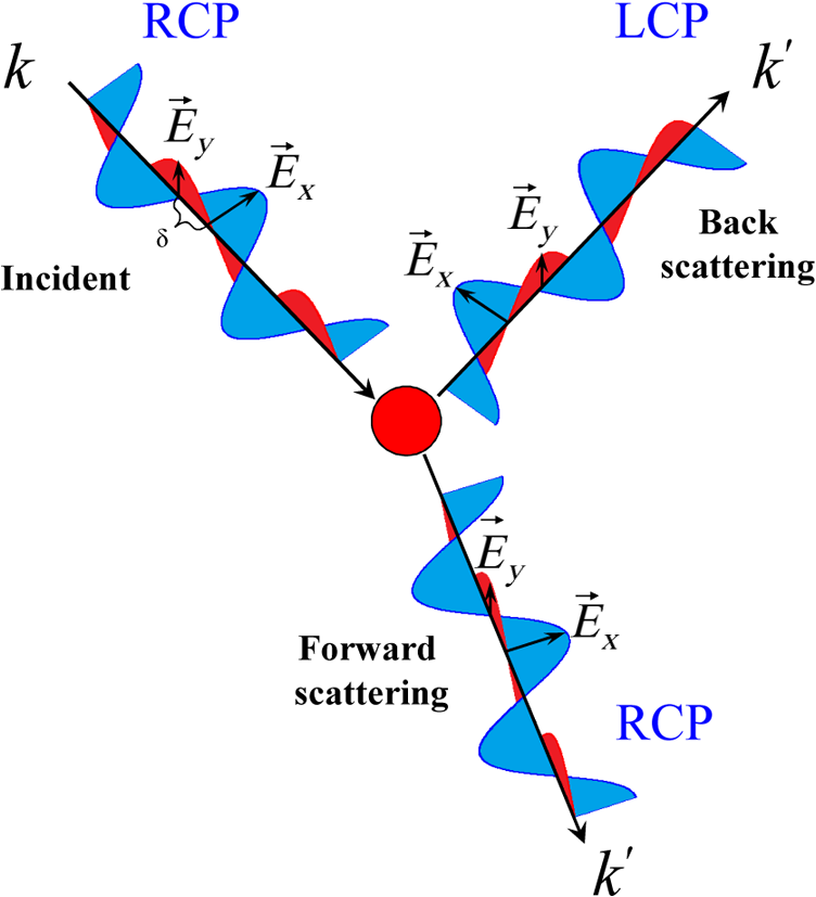 Therefore, considering the propagation of circularly polarized light through a turbid medium where multiple scattering events occur, the photon packets that have backscattered an odd number of times will correspond to a reversal in helicity, and thus, contribute the cross-polarized portion of the detected signal (). Correspondingly, the photon packets that have experienced an even number of backscattering events contribute to the copolarized signal () and the handedness of light is unchanged with respect to the incident polarization. Thus, for total number of helicity flips, either due to reflections on the medium boundary or backscattering events (), and taking into account interference, the copolarized light (that has preserved its helicity) is given by Similar equations can be written for depolarized light, defined by and , respectively. 4.Results and DiscussionFigure 5 presents the results of simulation of spatial distribution of , , and the depolarization ratio at the surface of the medium with various values of scattering anisotropy. These results both quantitatively and qualitatively are well agreed with the results of semianalytic MC model,15 a comparison of two MC models presented in Ref. 43. It can be clearly seen from Fig. 6 that significantly prevails over the intensity of the depolarized light . These results are in good agreement with the results of an analytical solution and other models (Table 1). The exact Milne solution for the Rayleigh noncoherent scattering gives 44–47 and ,44–47 while the results of MC modeling suggests and ; a similar value of has been obtained elsewhere.12 Fig. 6Surface distributions of , , and depolarization ratios of backscattered linearly polarized light for various values of scattering anisotropy: from the top , 0.5, 0.9 and 0.98. MC simulations were performed with noncoherent light () normally incident on the semi-infinite scattering medium with , , and detected over entire medium surface.  Table 1Comparison of the results of MC simulation with the exact solution by Milne and the results of alternative modeling (Refs. 44–47) Here, I∥ and I⊥ are counted as total intensity of I∥(x,y) and I⊥(x,y) profiles presented in Fig. 6.
Correspondingly, Fig. 7 presents the effective probing depth distribution (sampling volume) for , , and their difference, counted by analogy to the depolarization ratio. As one can see for the medium with high anisotropy of scattering () the effective probing depth of the linearly polarized component exceeds the propagation depth for the depolarized one . Therefore, with a significant increase of the photon packets’ pathlengths within the medium, the residual polarization in the backscattered light becomes preserved due to a large relative contribution of the photon packets’ trajectories with low orders of scattering (see Fig. 6). Fig. 7Corresponding sampling volumes for and , and the spatial distributions of the depolarization ratio DR simulated for the same parameters as in Fig. 5. 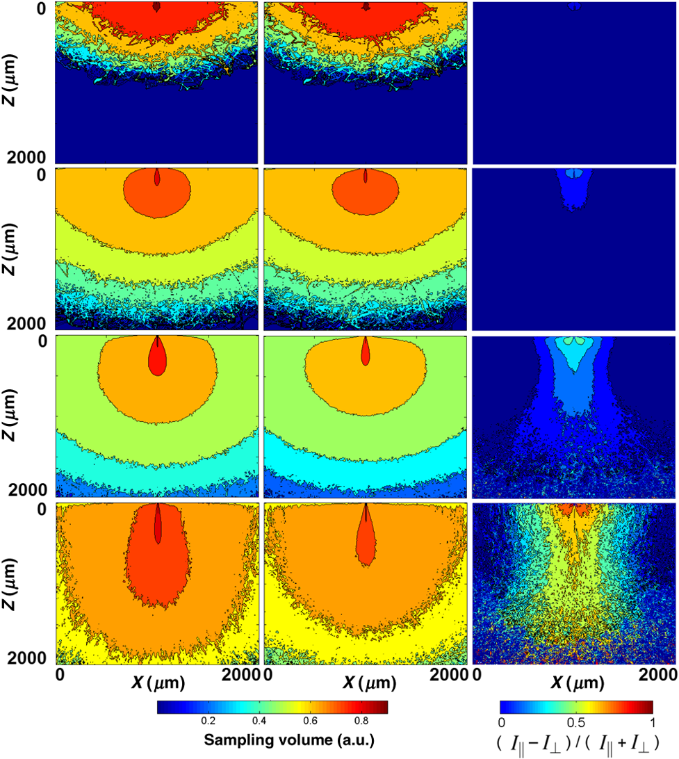 Figure 8 presents the surface distribution of , , and for backscattered linearly polarized light with various coherence lengths. The mutual interference between individual photon packets results in the formation of speckle patterns. Fig. 8Intensity distributions of and the depolarization ratios DR at the surface of the medium for backscattered linearly polarized light of various coherence lengths , from top: , 0.1 mm, 1 mm, 1 m, counted for a highly anisotropic scattering medium with , , .  Figure 9 shows the surface distribution of the portions of copolarized (RCP) and cross-polarized (LCP) intensities of backscattered light, and the helicity flip is clearly observed. Fig. 9Surface distributions of (top) and (bottom) polarized components of backscattered circularly polarized light, is the distance at the surface, ; counted for a semi-infinite scattering medium (, , , and ).  The results of simulation are in a good agreement with the analytical results and the results of alternative modeling; see Table 2 for details. Table 2Comparison of the results of MC simulation with the results of Milne’s solution and the results of alternative modeling (Refs. 44–47).
The model has been compiled, tested, and proven to work on Windows 8.1/Ubuntu GNU Linux 13.10 platforms. The time required to simulate photon packet trajectories is dependent on the parameters of the scattering medium and source-detector configuration. For instance, computing the surface distribution for the abovementioned detector parameters for a semi-infinite scattering medium (, , and ), illuminated by noncoherent light with , takes , and for coherent polarized light () with the same medium parameters. 5.ConclusionsIn the current report, we have introduced the electric field MC approach specifically developed for fast modeling of linearly and circularly polarized light propagation in highly scattering media. The model takes into account the coherent properties of light, the influence of total reflection and refraction at the medium boundary, helicity flip of circularly polarized light and interference. The results of modeling for both linearly and circularly polarized light are in good agreement with the results of the exact analytical solution by Milne and the results of alternative modeling. The developed MC approach is extremely flexible to operate with different optical properties of the medium, including scattering, absorption, refractive index, anisotropy of scattering, etc. The presented MC approach is a part of the O3MC model20 and can be easily extended to model light propagation in optically active and/or birefringent scattering media, as well as for scattering of complex vector laser beams in turbid tissue-like media. AcknowledgmentsAuthors acknowledge partial support provided by New Zealand Ministry of Business, Innovation, and Employment. ReferencesHandbook of Optical Biomedical Diagnostics, SPIE Press, Bellingham, WA
(2002). Google Scholar
D. J. Everset al.,
“Optical spectroscopy: current advances and future applications in cancer diagnostics and therapy,”
Future Oncol., 8
(3), 307
–320
(2012). http://dx.doi.org/10.2217/fon.12.15 FOUNBN 1479-6694 Google Scholar
N. GhoshI. A. Vitkin,
“Tissue polarimetry: concepts, challenges, applications, and outlook,”
J. Biomed. Opt., 16
(11), 110801
(2011). http://dx.doi.org/10.1117/1.3652896 JBOPFO 1083-3668 Google Scholar
V. V. TuchinL. V. WangD. A. Zimnyakov, Optical Polarization in Biomedical Applications, Springer-Verlag, Berlin, Heidelberg
(2006). Google Scholar
V. V. Tuchin, Handbook of Coherent-Domain Optical Methods. Biomedical Diagnostics, Environmental Monitoring, and Material Science, Springer, New York
(2013). Google Scholar
S. Svaenkov, Mueller Matrix Characterization of Biological Tissues, 437
–472 Springer, Dordrecht
(2011). Google Scholar
C. ZhuQ. Liu,
“Review of Monte Carlo modeling of light transport in tissues,”
J. Biomed. Opt., 18
(5), 050902
(2013). http://dx.doi.org/10.1117/1.JBO.18.5.050902 JBOPFO 1083-3668 Google Scholar
S. A. Prahlet al.,
“A Monte Carlo model of light propagation in tissue,”
Dosimetry of Laser Radiation in Medicine and Biology, 102
–111 SPIE Press, Bellingham, WA
(1989). Google Scholar
S. L. JacquesL. V. Wang,
“Monte Carlo modeling of light transport in tissues,”
Optical Thermal Response of Laser Irradiated Tissue, 73
–100 Plenum, New York
(1995). Google Scholar
V. KuzminI. Meglinski,
“Coherent effects of multiple scattering for scalar and electromagnetic fields: Monte-Carlo simulation and Milne-like solutions,”
Opt. Commun., 273
(2), 307
–310
(2007). http://dx.doi.org/10.1016/j.optcom.2007.01.025 OPCOB8 0030-4018 Google Scholar
V. KuzminI. Meglinski,
“Numerical simulation of coherent back-scattering and temporal intensity correlations in random media (overview),”
Quantum Electron., 36
(11), 990
–1002
(2006). http://dx.doi.org/10.1070/QE2006v036n11ABEH013338 QUELEZ 1063-7818 Google Scholar
L. Rojas-Ochoaet al.,
“Depolarization of backscattered linearly polarized light,”
J. Opt. Soc. Am. A, 21
(9), 1799
–1804
(2004). http://dx.doi.org/10.1364/JOSAA.21.001799 JOAOD6 0740-3232 Google Scholar
H. Subramanianet al.,
“Modeling low-coherence enhanced backscattering using Monte Carlo simulation,”
Appl. Opt., 45
(24), 6292
–6300
(2006). http://dx.doi.org/10.1364/AO.45.006292 APOPAI 0003-6935 Google Scholar
J. SawickiN. KastorM. Xu,
“Electric field Monte Carlo simulation of coherent backscattering of polarized light by a turbid medium containing Mie scatterers,”
Opt. Express, 16
(8), 5728
–5738
(2008). http://dx.doi.org/10.1364/OE.16.005728 OPEXFF 1094-4087 Google Scholar
A. Radosevichet al.,
“Open source software for electric field Monte Carlo simulation of coherent backscattering in biological media containing birefringence,”
J. Biomed. Opt., 17
(11), 115001
(2012). http://dx.doi.org/10.1117/1.JBO.17.11.115001 JBOPFO 1083-3668 Google Scholar
I. Meglinskiet al.,
“Simulation of polarization-sensitive optical coherence tomography images by a Monte Carlo method,”
Opt. Lett., 33
(14), 1581
–1583
(2008). http://dx.doi.org/10.1364/OL.33.001581 OPLEDP 0146-9592 Google Scholar
M. Y. Kirillinet al.,
“Effect of photons of different scattering orders on the formation of a signal in optical low-coherence tomography of highly scattering media,”
Quantum Electron., 36
(11), 990
–1002
(2006). http://dx.doi.org/10.1070/QE2006v036n11ABEH013338 QUELEZ 1063-7818 Google Scholar
M. Kirillinet al.,
“Contrasting properties of gold nanoshells and titanium dioxide nanoparticles for optical coherence tomography imaging of skin: Monte Carlo simulations and in vivo study,”
J. Biomed. Opt., 14
(2), 021017
(2009). http://dx.doi.org/10.1117/1.3122373 JBOPFO 1083-3668 Google Scholar
M. Kirillinet al.,
“Simulation of optical coherence tomography images by Monte Carlo modeling based on polarization vector approach,”
Opt. Express, 18
(21), 21714
–21724
(2010). http://dx.doi.org/10.1364/OE.18.021714 OPEXFF 1094-4087 Google Scholar
A. DoroninI. Meglinski,
“Online object oriented Monte Carlo computational tool for the needs of biomedical optics,”
Biomed. Opt. Express, 2
(9), 2461
–2469
(2011). http://dx.doi.org/10.1364/BOE.2.002461 BOEICL 2156-7085 Google Scholar
A. DoroninI. Meglinski,
“Peer-to-peer Monte Carlo simulation of photon migration in topical applications of biomedical optics,”
J. Biomed. Opt., 17
(9), 090504
(2012). http://dx.doi.org/10.1117/1.JBO.17.9.090504 JBOPFO 1083-3668 Google Scholar
D. KirkW. Hwu, Programming Massively Parallel Processors: A Hands-on Approach, Morgan Kaufmann(2010). Google Scholar
S. Schach, Object-Oriented and Classical Software Engineering, 7th Ed.McGraw-Hill, New York
(2006). Google Scholar
“CUDA C Programming Guide,”
CUDA Toolkit Documentation,
(2013). Google Scholar
E. Wolf, Introduction to the Theory of Coherence and Polarization of Light, Cambridge University, New York
(2007). Google Scholar
X. WangL. Wang,
“Propagation of polarized light in birefringent turbid media: time-resolved simulations,”
Opt. Express, 9
(5), 254
–259
(2001). http://dx.doi.org/10.1364/OE.9.000254 OPEXFF 1094-4087 Google Scholar
X. WangL. Wang,
“Propagation of polarized light in birefringent turbid media: a Monte Carlo study,”
J. Biomed. Opt., 7
(3), 279
–290
(2002). http://dx.doi.org/10.1117/1.1483315 JBOPFO 1083-3668 Google Scholar
S. GangnusS. MatcherI. Meglinski,
“Monte Carlo modeling of polarized light propagation in biological tissues,”
Laser Phys., 14
(6), 886
–891
(2004). LAPHEJ 1054-660X Google Scholar
J. Ramella-RomanS. PrahlS. Jacques,
“Three Monte Carlo programs of polarized light transport into scattering media: part I,”
Opt. Express, 13
(12), 4420
–4438
(2005). http://dx.doi.org/10.1364/OPEX.13.004420 OPEXFF 1094-4087 Google Scholar
R. C. Jones,
“A new calculus for the treatment of optical systems. I. Description and discussion of the new calculus,”
J. Opt. Soc. Am., 31
(7), 488
–493
(1941). http://dx.doi.org/10.1364/JOSA.31.000488 JOSAAH 0030-3941 Google Scholar
H. HurwitzR. C. Jones,
“A new calculus for the treatment of optical systems. II. Proof of three general equivalence theorems,”
J. Opt. Soc. Am., 31
(7), 493
–499
(1941). http://dx.doi.org/10.1364/JOSA.31.000493 JOSAAH 0030-3941 Google Scholar
A. GeraldJ. M. Burch, Introduction to Matrix Methods in Optics, 1st ed.John Wiley & Sons, London
(1975). Google Scholar
E. Collett, Field Guide to Polarization, SPIE, Bellingham, WA
(2005). Google Scholar
F. PedrottiL. PedrottiL. Pedrotti, Introduction to Optics, 3rd ed.Prentice Hall, Upper Saddle River, New Jersey
(2007). Google Scholar
P. Yeh,
“Extended Jones matrix method,”
J. Opt. Soc. Am., 72
(4), 507
–513
(1982). http://dx.doi.org/10.1364/JOSA.72.000507 JOSAAH 0030-3941 Google Scholar
R. G. Newton,
“Optical theorem and beyond,”
Am. J. Phys., 44
(7), 639
–642
(1976). http://dx.doi.org/10.1119/1.10324 AJPIAS 0002-9505 Google Scholar
P. S. CarneyE. WolfG. S. Agarwal,
“Statistical generalizations of the optical cross-section theorem with application to inverse scatter,”
J. Opt. Soc. Am. A, 14
(12), 3366
–3371
(1997). http://dx.doi.org/10.1364/JOSAA.14.003366 JOAOD6 0740-3232 Google Scholar
D. ChurmakovI. MeglinskiD. Greenhalgh,
“Influence of refractive index matching on the photon diffuse reflectance,”
Phys. Med. Biol., 47
(23), 4271
–4285
(2002). http://dx.doi.org/10.1088/0031-9155/47/23/312 PHMBA7 0031-9155 Google Scholar
D. Goldstein, Polarized Light, 2nd ed.Marcel Dekker, New York
(2007). Google Scholar
D. ClarkeJ. F. Grainger, Polarized Light and Optical Measurements, Pergamon, New York
(1971). Google Scholar
M. BornE. Wolf, Principles of Optics: Electromagnetic Theory of Propagation, Interference and Diffraction of Light, 6th ed.Pergamon, London
(1986). Google Scholar
Y. Kimet al.,
“Circular polarization memory effect in low-coherence enhanced backscattering of light,”
Opt. Lett., 31
(18), 2744
–2746
(2006). http://dx.doi.org/10.1364/OL.31.002744 OPLEDP 0146-9592 Google Scholar
A. Doroninet al.,
“Comparison of two Monte Carlo models of propagation of coherent polarized light in turbid scattering media,”
Proc. SPIE, 8952 895214
(2014). PSISDG 0277-786X Google Scholar
T. NieuwenhuizenJ. Luck,
“Skin layer of diffusive media,”
Phys. Rev. E, 48
(1), 569
–588
(1993). http://dx.doi.org/10.1103/PhysRevE.48.569 PLEEE8 1063-651X Google Scholar
E. AmicJ. LuckT. M. Nieuwenhuizen,
“Anisotropic multiple scattering in diffusive media,”
J. Phys. A Math. Gen., 29
(16), 4915
–4955
(1996). http://dx.doi.org/10.1088/0305-4470/29/16/016 JPHAC5 0305-4470 Google Scholar
V. Kuzmin,
“The Milne problem solution for the temporal correlation function of an electromagnetic field,”
Opt. Spectrosc., 93
(3), 439
–448
(2002). http://dx.doi.org/10.1134/1.1509828 OPSUA3 0030-400X Google Scholar
V. KuzminE. Aksenova,
“A generalized Milne solution for the correlation effects of multiple light scattering with polarization,”
J. Exp. Theor. Phys., 96
(5), 816
–831
(2003). http://dx.doi.org/10.1134/1.1581936 JTPHES 1063-7761 Google Scholar
BiographyAlexander Doronin is a PhD candidate working in the Biophotonics and Biomedical Imaging Research Group at the University of Otago, New Zealand. His research interests include biophotonics, light-tissue interaction, Monte Carlo computational modeling, parallel programming on GPUs using NVIDIA CUDA, optical imaging (OCT, PS-OCT, Doppler OCT, NIRS), image processing, development of high-performance computing systems, and algorithm optimization techniques for biomedical/optical diagnostic needs. Callum Macdonald is a PhD student in the Department of Physics at the University of Otago, New Zealand. His current areas of research interest include light-tissue interactions, optical coherence tomography (OCT), multiple scattering of light, and polarization sensitive imaging of biological structures. Igor Meglinski is a head of biophotonics and biomedical imaging in the Department of Physics at the University of Otago, New Zealand. His research interests lie at the interface between physics, medicine, and biological sciences, focusing on the development of new noninvasive imaging/diagnostic techniques and their application in medicine and biology, material sciences, pharmacy, food, environmental monitoring, and health care industries. He is fellow of the Institute of Physics and a fellow of SPIE. |


