
|
|
|
Confocal fluorescence endomicroscopy has shown great promise as an approach to real-time optical biopsy and has recently been successfully commercialized.1 Using fiber imaging bundles to relay light to and from the tissue allows the probes to be compact and passive, while still delivering high-resolution microscopy images at near-video rates. Fiber bundles can also be used for fluorescence endomicroscopy under widefield illumination, providing a low-cost alternative to confocal imaging for selected applications.2 A further possibility, reflectance-mode endomicroscopy, has been demonstrated on several occasions, under both confocal3,4 and widefield5,6 operation, but has so far failed to have a similar clinical impact. Reflectance imaging requires a method to efficiently reject back-reflections from the bundle end-faces, as these will otherwise tend to overwhelm the signal from the tissue.7 Simple digital subtraction, while possible, is an unattractive option which results in a low signal-to-noise ratio (SNR) and poor dynamic range.6 In confocal systems, refractive index matching at the bundle faces allows back-reflections to be shifted away from the focal plane so that they are blocked by the detector pinhole.3 Alternatively, pulsed laser illumination and time-of-flight measurements can be used to distinguish between the tissue signal and reflections from the proximal tip.8 However, neither of these approaches is suitable for reflectance endomicroscopy under widefield illumination. The problem is avoided in the technique known as endocytoscopy by placing an illumination source adjacent to the distal imaging optics.9 Light scatters from tissue behind the field-of-view to illuminate superficial tissue layers within the region of interest. This concept has been used for several prototype camera-based endocytoscopes, and we recently demonstrated a similar technique using a fiber bundle.10 However, this is not true reflectance endomicroscopy; the tissue is essentially imaged in pseudotransmission mode and the results are dependent on the layer structure of the tissue. An approach for true widefield reflection endomicroscopy was suggested by Sun et al., who used crossed polarization to reject much of the specular reflection from the proximal end of the bundle.5 This allowed them to image cultured cells and excised oral cancer tissue, albeit with relatively low SNR. In 2011, Liu et al. suggested an alternative method in which the numerical aperture of the fiber bundle is shared between illumination and collection, a technique conceptually similar to darkfield microscopy.6 Again this system was demonstrated using cell cultures with an apparently higher SNR. In this article, we present a new method to eliminate back-reflections from the proximal end of the bundle and to reduce them from the distal end. Rather than illuminating the proximal end of the bundle, we instead use a separate multimode (MM) illumination fiber to inject light into the bundle near the distal tip. Light propagates along the short remaining portion of the bundle (primarily through the cladding) to epi-illuminate the tissue without being fully guided by the cores. Back-reflections from the proximal tip are eliminated, while those from the distal end are significantly reduced. This makes it feasible to use a color camera, providing an additional source of contrast. We tested this new illumination scheme with leached fiber imaging bundles. Leached bundles contain several thousand fibers that are fixed into short ferrules at either end of the bundle but are not bound together along the remainder of the length. This makes it possible to couple light from the illumination fiber by inserting it between the fiber strands, but with the disadvantage that the fiber-fiber spacing is typically double than that of the fused silica bundles more typically used in endomicroscopy. To validate our approach, we coupled a warm white LED (Thorlabs, Ely, UK MWWHF1) into an MM illumination fiber (Thorlabs FT400EMT) with a 400-μm core diameter and an NA of 0.4. This was then stripped of its coating using a fiber stripping tool (Thorlabs T21S31), inserted into the sheath of a 17,000 core (8-μm spacing), 80-cm long leached imaging fiber bundle (Schott #1251343, Stafford, UK) and positioned flush against the distal ferrule (4 mm from the distal tip), as shown in Fig. 1(a). Heat shrink tubing around the insertion point held the illumination fiber in its position, although a method of fixing the fiber at the distal end would be preferable as it would ensure that there is no movement relative to the bundle. Fig. 1Probe design showing (a) schematic of probe assembly (not to scale); (b and c) photographs of probe; (d) distal end of probe showing illumination; (e) zoom on distal end showing field-of-view; (f) raw image of USAF group 6 elements 2-6; and (g) processed image. 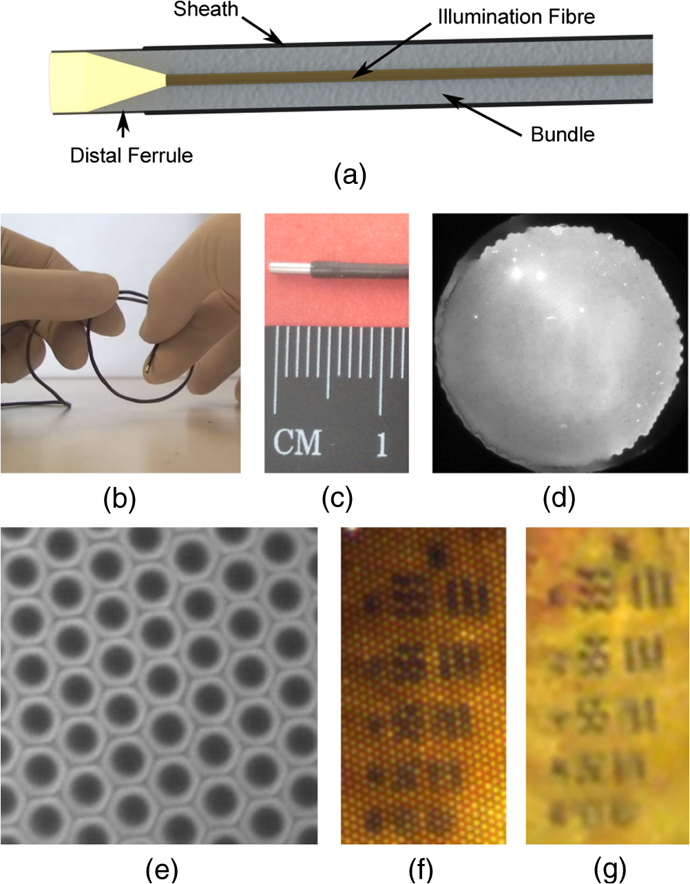 The MM fiber caused the bundle to stiffen, but it maintained a minimum radius of curvature of less than 1.5 cm and an outer diameter of approximately 1.3 mm, as shown in Figs. 1(b) and 1(c). We measured a power of 0.4 mW to the tissue, compared with 6.5 mW emanating from the illumination fiber, meaning that only approximately 6% is coupled to the tissue. Although this throughput is low, it is sufficient for reflectance-mode imaging. For these experiments, the distal end of the bundle was placed in direct contact with the tissue under study. The distal end of the imaging bundle was imaged onto a color CCD (Thorlabs DCU224C) by a achromatic microscope objective (Edmund Optics #67-706, York, UK) with the tube length selected so as to give approximately 5 pixels per core. The apparent oversampling allowed the cores to be resolved in all three color planes. We read out 24-bit (8 bits per color plane) RGB images at 15 Hz with an integration time of 66 ms and variable camera hardware gain. A drawback of the approach is that light is scattered back into any fiber strands that are broken near the distal ferrule, resulting in white spots and blooming in the image. Some fibers were broken when we inserted the illumination fiber, and we noticed that additional damage was accumulated while the probe was in use. We expect that an improved assembly procedure would alleviate this problem and extend the life of the probe. As the edge of the fiber bundle was particularly susceptible to damage, we performed reconstruction only over a 700-μm diameter region, reducing the field-of-view from 1 mm. To remove the honeycomb-like fiber bundle core pattern from the final images, we implemented an algorithm similar to one described by Le Goualher et al. for confocal fluorescence endomicroscopy.11 In the calibration stage, we acquire an image (or average over a video) of a strongly reflecting, uniform target, for which the core pattern is clearly visible, and select the green color plane. The center of each core is found by a regional maxima algorithm and recorded. Cores with saturated or low intensity values are assumed broken and removed from the record. A Delaunay triangulation mesh is then formed over the core positions. For each pixel in the reconstructed image, the algorithm identifies the enclosing triangle, converts the pixel’s location to triangular barycentric coordinates (essentially a measure of its distance from each vertex), and stores this information in a look-up table. To reconstruct subsequent images, each pixel is assigned an intensity value, , by linear interpolation between the intensities of the cores lying on the three vertices of the enclosing triangle where is the intensity value of the core at vertex , and is the corresponding precalculated barycentric coordinate for that reconstruction pixel. The reconstruction is performed separately for each of the three color planes.To account for the variations in illumination intensity and coupling efficiency of the different fibers, we also implemented an intensity correction. This is performed by first reconstructing the image used for calibration. As this image should be of uniform intensity, it is possible to calculate a two-dimensional correction map which, when multiplied by the reconstructed image, renders it uniform. This intensity correction map is then applied to all subsequent images. To confirm that the tissue was epi-illuminated by light from the fiber bundle, we imaged the distal end of the probe onto a monochrome CCD camera. Figure 1(d) shows the entire face of the bundle, confirming that the sample is epi-illuminated across the whole field-of-view. There is some nonuniformity in the illumination (the lowest intensity is approximately 50% of the maximum in this case) which depends on the exact positioning of the illumination fiber. This is corrected by the reconstruction algorithm discussed above. Figure 1(e) shows a area of the bundle, demonstrating that the geometry is very inefficient for coupling light into the cores and that illumination is primarily delivered via the cladding. The power in the cladding decays rapidly over longer distances. While there are no back-reflections from the proximal tip, the residual back-reflection signal from the distal tip was approximately 1% of the image signal from a broadband mirror. In principle, such a reduction from the distal end may also be achievable using index matching,12 but this would require the addition of a distal optical assembly. In Figs. 1(f) and 1(g), we show a zoom on an image of a USAF resolution target with and without reconstruction, respectively. From inspection, we estimate that the limiting resolution is given by Element 6-3, corresponding to a resolution of 12.4 μm, broadly consistent with the theoretically expected value of 14 μm for Nyquist sampling with a hexagonal grid with 8-μm pitch. Comparison between Figs. 1(f) and 1(g) also serves to demonstrate the impact of the reconstruction algorithm, showing that the reconstruction grid is sufficiently fine to avoid the degrading resolution. Representative images from several phantoms and tissue samples are shown in Fig. 2. The image of a part of a printed character on a sheet of white paper in Fig. 2(a) demonstrates that the system is functioning in epi-reflectance mode. We confirmed that it was not possible to image this kind of strongly reflecting layer with the fiber bundle endocytoscopy system.10 We then show an image from an onion in Fig. 2(b) for comparison with similar images from previous widefield reflectance endomicroscopy systems.5,6 Fig. 2Imaging results from phantoms and ex vivo tissue samples. (a) Printed ink on paper; (b) unstained onion skin; (c) unstained porcine fatty tissue; (d) unstained porcine stomach mucosa; (e) porcine colon mucosa and (f) porcine small bowel mucosa both stained with 0.1% toluidine blue for 2 min; (g) mosaic of stomach mucosa stained with toluidine blue. Scale bars are 100 μm (a–f) and 1 mm (g).  The ex vivo porcine adipose tissue shown in Fig. 2(c) shows good contrast, and the fat cells can be resolved. Porcine stomach mucosa shown in Fig. 2(d) exhibits less endogenous contrast, but the mucosal crypts are identifiable. Topical toluidine blue 0.1% was used to stain porcine colonic and small bowel mucosa shown in Figs. 2(e) and 2(f), respectively. This provides sufficient contrast for the colonic crypts and villi of the small bowel to be easily identified and produces images similar to fiber bundle endocytoscopy. Finally, in Fig. 2(g), we show field-of-view expansion by offline stitching (mosaicking) of 223 images. These were acquired as the probe was moved across the surface of ex vivo porcine stomach tissue stained with toluidine blue. This is a common technique in confocal endomicroscopy.13 This mosaic was created using a cross-correlation algorithm similar to the one previously described for widefield fluorescence endomicroscopy.14 Reflectance endomicroscopy has been reported on several occasions, but we have demonstrated here a new approach that virtually eliminates back-reflections and shown that color imaging is possible. We have also shown the applicability of image reconstruction and mosaicking techniques previously used with fluorescence endomicroscopy. The method is only suitable for widefield endomicroscopy, because it precludes the transfer of a laser scanning pattern for confocal sectioning or of a grating pattern for structured illumination. Resolution is currently limited by the large fiber-fiber spacing in the bundle, but it may be possible to improve this by incorporating a distal optical assembly. Further work could integrate this technique into fluorescence endomicroscopy systems, and so these results should assist the development of the next generation of low-cost endomicroscopes. AcknowledgmentsThis work was supported by EPSRC Grant EP/I027769/1: SMART Endomicroscopy. Thanks to Dr. Tou Pin Chang for assistance with tissue preparation. ReferencesJ. M. Jabbouret al.,
“Confocal endomicroscopy: instrumentation and medical applications,”
Ann. Biomed. Eng., 40
(2), 378
–397
(2012). http://dx.doi.org/10.1007/s10439-011-0426-y ABMECF 0090-6964 Google Scholar
M. C. Pierceet al.,
“Low-cost endomicroscopy in the esophagus and colon,”
Am. J. Gastroenterol., 106
(9), 1722
–1724
(2011). http://dx.doi.org/10.1038/ajg.2011.140 AJGAAR 0002-9270 Google Scholar
R. JuskaitisT. Wilson,
“Real-time white light reflection confocal microscopy using a fibre-optic bundle,”
Scanning, 19
(1), 15
–19
(1997). http://dx.doi.org/10.1002/sca.4950190102 SCNNDF 0161-0457 Google Scholar
J. Knittelet al.,
“Endoscope-compatible confocal microscope using a gradient index-lens system,”
Opt. Commun., 188
(5), 267
–273
(2001). http://dx.doi.org/10.1016/S0030-4018(00)01164-0 OPCOB8 0030-4018 Google Scholar
J. Sunet al.,
“Needle-compatible single fiber bundle image guide reflectance endoscope,”
J. Biomed. Opt., 15
(4), 040502
(2010). http://dx.doi.org/10.1117/1.3465558 JBOPFO 1083-3668 Google Scholar
X. Liuet al.,
“Dark-field illuminated reflectance fiber bundle endoscopic microscope,”
J. Biomed. Opt., 16
(4), 046003
(2011). http://dx.doi.org/10.1117/1.3560298 JBOPFO 1083-3668 Google Scholar
P. M. Lane,
“Terminal reflections in fiber-optic image guides,”
Appl. Opt., 48
(30), 5802
–5810
(2009). http://dx.doi.org/10.1364/AO.48.005802 APOPAI 0003-6935 Google Scholar
M. Nakaoet al.,
“Optical biopsy of early gastroesophageal cancer by catheter-based reflectance-type laser-scanning confocal microscopy,”
J. Biomed. Opt., 13
(5), 054043
(2008). http://dx.doi.org/10.1117/1.2983674 JBOPFO 1083-3668 Google Scholar
T. Ohigashiet al.,
“Endocytoscopy: novel endoscopic imaging technology for in-situ observation of bladder cancer cells,”
J. Endourol., 20
(9), 698
–701
(2006). http://dx.doi.org/10.1089/end.2006.20.698 JENDE3 0892-7790 Google Scholar
M. Hugheset al.,
“Fiber bundle endocytoscopy,”
Biomed. Opt. Express, 4
(12), 2781
–2794
(2013). http://dx.doi.org/10.1364/BOE.4.002781 BOEICL 2156-7085 Google Scholar
G. L. Goualheret al.,
“Towards optical biopsies with an integrated fibered confocal fluorescence microscope,”
in MICCAI 2004,
761
–768
(2004). Google Scholar
A. Kanoet al.,
“Ultrathin single-channel fiberscopes for biomedical imaging,”
J. Biomed. Opt., 18
(11), 016013
(2013). http://dx.doi.org/10.1117/1.JBO.18.1.016013 JBOPFO 1083-3668 Google Scholar
T. Vercauterenet al.,
“Robust mosaicing with correction of motion distortions and tissue deformations for in vivo fibered microscopy,”
Med. Image Anal., 10
(5), 673
–692
(2006). http://dx.doi.org/10.1016/j.media.2006.06.006 MIAECY 1361-8415 Google Scholar
N. Bedardet al.,
“Real-time video mosaicing with a high-resolution microendoscope,”
Biomed. Opt. Express, 3
(10), 2428
–2435
(2012). http://dx.doi.org/10.1364/BOE.3.002428 BOEICL 2156-7085 Google Scholar
|


