

|
|
1.IntroductionIn this paper, we present the experimental implementation for a concept for the construction of inhomogeneous phantoms for imaging in diffuse media based on totally absorbing objects that was proposed in the previous companion paper.1 This work stems from the outcome of a large collaboration among seven institutions from four countries within the framework of the European nEUROPt Project that put great emphasis on standardization approaches to assess the performance of noninvasive optical brain imagers. The key motivation for these activities is that, while the investigation of the human body by diffusely propagated light has brought a wealth of different techniques and applications2 (e.g., optical mammography,3–5 neoadjuvant chemotherapy monitoring,6 breast cancer risk assessment,7 brain functional imaging,2,8,9 neuromonitoring,10 muscle oximetry,11 study of epilepsy,12,13 investigation of bone and joint pathologies,14 and photodynamic therapy dosimetry15), there is still a compelling need for standardization and quality assessment of instruments to bring the whole field to a clinically mature stage.16 Indeed, the large variety of techniques and instruments addressing diverse clinical problems demand some clearly identified and shared procedures to test and validate the optical systems. Common standardization tools help in comparing results obtained in different clinical studies, permit one to grade different instruments’ performances or subsequent upgrades of the same system, and address the research—particularly at the industrial level—toward those parameters that best match the clinical needs. This process necessarily passes through the proposition of good reproducible and reliable phantoms and procedures, the buildup of a widespread consensus in the scientific community and, at last, the adoption of good laboratory practices and formalization by standardization bodies. Clearly, the availability of well characterized, reliable, reproducible, and realistic phantoms is essential for this process. Concerning homogeneous phantoms, the status is quite advanced, with many tested options,17–24 off-the-shelf solid phantoms with well characterized and documented optical properties,25 and good agreement in liquid phantoms’ characterization in multilaboratory studies.26 Conversely, the situation of inhomogeneous phantoms is less consolidated due to many criticalities and large combinations of geometries and optical properties. Different approaches have been proposed. Without claiming to give a comprehensive review of the whole field here—more information can be gathered in the review papers24,27 and a recent special issue of Biomed. Opt. Express16—we just recall that three schemes can be adopted for this purpose, namely liquid–liquid,28 liquid–solid,29–31 and solid–solid32–34 structures, each of them with different advantages and criticalities. Liquid–liquid phantoms realize inhomogeneous properties by embedding a liquid solution (typically based on intralipid and ink) in a small cell—made of glass, thin plastic, or latex—suspended within another homogeneous solution. The advantages are the great flexibility and the reliability in the choice of optical properties, the possibility to move the inclusion within the medium, and also to realize a purely homogeneous reference state. Conversely, the main concerns are the possible light guiding effects in the small cell walls, the challenging fabrication and the exact placement of soft-flexible objects, the great perturbation produced by transparent walls in the measurement tank for reflectance measurements,35 and generally the complex handling procedures in routine clinical settings. The liquid–solid approach replaces the liquid perturbation with a solid one crafted from a solid phantom or from a liquid phantom solidified with the addition of a hardener, e.g., agar32 or polyacrylamide.31 In this case, the handling and the replacement of the perturbation is easier, and light-guiding effects are avoided. On the other hand, the exact matching of optical properties is not trivial due to the application of two-different phantom recipes, the fact that the hardener may change the inclusion properties,32 and the refractive index mismatch between the solid inclusion and its surroundings has to be considered. Solid–solid structures are definitely the best solution for routine use in clinics and also as a fast and reliable option in the laboratory. Yet, the fabrication of such phantoms is not straightforward. It is not possible to replace or move the perturbation, and it is not trivial to precisely measure the optical properties of the inclusion. Among this class, one can also mention electrically activated phantoms where a local increase in the absorption properties is produced by localized heating of targets impregnated with thermochromic pigment33 or liquid-crystal–based dynamic phantom for quality assurance of functional near-infrared spectroscopy devices.36 Dynamic changes can be easily achieved with such a rugged solid phantom, yet exact control and reproducibility are still an issue. Our approach presented in the following is based on the recently formulated equivalence relation (ER) between realistic and totally absorbing optical inhomogeneities that states the equivalence between the perturbation produced by a given absorption inhomogeneity embedded in a diffusive medium and that produced by black object of appropriate volume.1 Generally speaking, for a given reduced scattering coefficient in the background medium, the ER identifies—within the set of all possible absorption inhomogeneities—subclasses of equivalent objects producing the same effect in terms of absorption perturbation. Each subclass contains only one totally absorbing spherical inclusion, but contains an infinite variety of absorption inhomogeneities with different combinations of the absorption variation , volume, and shape, all producing the same absorption perturbation. Apart from a few extreme cases—as for very low absorption perturbations quite close to the source or the detector—the correspondence is general, holds true both for time-resolved (TR) and continuous wave (CW) approaches, and is fairly independent of the measurement geometry, source–detector distance, and location of the inhomogeneity as well as of the background absorption coefficient (). The inhomogeneous phantom proposed hereafter is based on the suspension of black polyvinyl chloride (PVC) cylinders within a water suspension of intralipid and ink. Although totally absorbing objects (e.g., black PVC cylinders) have already been used in diffuse optical spectroscopy experiments,37–41 their equivalence to realistic perturbations was never stated and an extensive study on their aptness to mimic realistic and controlled situations is still lacking. In the following, we will first describe the design of the phantom and the key components (Sec. 2). Then, we will analyze—using Monte Carlo (MC) simulations and analytical solutions of the diffusion equation (DE)—possible sources of inaccuracies in the experimental implementation (Sec. 3). Finally, we will show the experimental validation of the proposed phantom obtained with comparisons of TR diffuse reflectance measurements with the results of MC simulations (Sec. 4). 2.Phantom ConstructionLiquid phantoms offer a high flexibility regarding changes of optical properties and realization of inhomogeneous geometries. The preparation of liquid phantoms with known optical properties is based on intralipid-20% as a diffusive medium and on India ink as an absorber by using a water dilution of these two components. These components have been thoroughly characterized in terms of a reduced scattering coefficient and absorption coefficient for intralipid, and an absorption coefficient for ink, both with CW measurements22,26,42–46 and TR measurements.26,47 The amounts of components to be mixed are solely determined by accurate weighing, which ensures that the concentrations are known with high accuracy. Intralipid is a pharmaceutical product used for parenteral nutrition consisting of small fat droplets suspended in water that make it a highly scattering medium. The uniformity among batches is excellent and the optical properties remain stable for a long time. Measurements on samples with expiration dates spanning over about 10 years22 showed that for the reduced scattering coefficient batch-to-batch variations were within 2% and that the absorption coefficient is very small and practically equal to the absorption of water. Furthermore, very similar optical properties have been measured for several fat emulsions of different brands having a composition similar to intralipid.48 These results are not unexpected, since these fat emulsions are pharmaceutical products with a well-defined composition that undergo stringent quality controls. In particular, the size distribution of fat particles, which significantly affects the scattering properties, should be carefully controlled to avoid the formation of large particles that may cause thrombosis in small vessels. We, therefore, expect that the optical properties will remain almost unchanged as long as the composition and the production process remain unchanged. As for India ink, it is an insoluble suspension of carbon particles in water, chemically and spectroscopically stable, nontoxic, nonfluorescent, and it does not alter the scattering properties of intralipid when mixed in water. Its main drawback is that the particles may sediment over time giving rise to clusters, therefore, to obtain reproducible and stable optical properties, it is necessary to apply ultrasound before using. Furthermore, since particles are large enough to scatter an appreciable fraction of visible and near-infrared light, measuring the absorption coefficient of India ink becomes difficult. In Ref. 46, the optical properties of samples from different brands and different batches have been systematically investigated. Measurements showed large brand-to-brand and batch-to-batch variations (more than a factor of two) both for absorption and extinction coefficients. However, the ratio between the absorption and the extinction coefficient showed small variations: the value averaged over the different brands and batches was 0.839 at 632.8 nm and 0.885 at 751 and 833 nm, with deviations from the average within about 4%. These results suggest that the measurements of the extinction coefficient (accurate values can be easily obtained with measurements of collimated transmittance), together with the results of Ref. 46 can be used to predict the absorption coefficient of India ink with an uncertainty probably less than 4%. Results for the intrinsic optical properties of intralipid and India ink, almost identical to those shown in Refs. 22 and 46, have been recently obtained by a multicenter experiment that involved nine laboratories with different instrumentations and methodologies.26 These results indicate that the optical properties of a mixture of intralipid and India ink in water can be predicted by making use of the intrinsic optical properties shown in Refs. 22, 26, and 46. A phantom with well-known optical properties can therefore be obtained by carefully controlling the concentrations of intralipid and India ink with accurate weighing of the different components and without the need for complicated characterization measurements. A scattering cell made of black PVC is a suitable container to prepare both homogeneous and inhomogeneous liquid phantoms (see Fig. 1). Photons impinging on the black walls are reflected or absorbed and uncontrolled guiding effects are avoided. Boundary conditions are therefore well known and they can be precisely modelled both in the MC simulations and with analytical models. The scattering cell used for the implementation of the inhomogeneous phantom has a frontal wall of black PVC with small transparent windows that allow the laser light to enter the diffusive medium, and the re-emitted light to be collected outside the cell. In particular, we considered two kinds of walls at the entrance surface designed with different sizes and distances of the small transparent windows, denoted as Cell #1 and Cell #2. Cell #1 had a 3-mm frontal wall and five transparent circular windows (separation 10 mm) having a diameter of 3 mm; Cell #2 had a 2-mm frontal wall and three transparent circular windows (separations 20 mm, 30 mm) having a diameter of 7 mm. The size of the windows has been chosen to minimally perturb light propagation and has been adapted to the size of the fiber bundles used. The perturbations introduced by the scattering cell on light propagation (finite size, effect of the windows) will be analyzed in Sec. 3. Since it is very difficult to make a small inhomogeneity with well-known optical properties, the authors proposed in the previous paper1 using a totally absorbing inclusion and having the volume determined by the ER in order to mimic the perturbation due to small localized variations of the absorption coefficient. This is possible since for a fixed position of the inhomogeneity the shape of the TR relative perturbation is almost independent of both the absorption coefficient and the volume of the inhomogeneity. Small black PVC cylinders with different dimensions (see Fig. 1) immersed in the liquid phantom were used to mimic real perturbations exploiting the ER, as discussed in Sec. 1. The plastic inclusion is held by a rigid metallic wire (0.5-mm music wire) painted white in order to reduce the perturbation introduced on the shape of the TR response. The negligible effect of the perturbation due to the white wire was verified by performing TR measurements with the wire placed in different positions inside the liquid phantoms (data not shown). Fig. 1(a) Scattering cell #2 used for liquid phantom experiments; (b) Detail of the frontal wall; (c) polyvinyl chloride (PVC) cylinders of various size, with of 2.3, 3.2, 4, 5, 6.8, 8.6 mm corresponding to volumes , 25, 50, 100, 250, 500.  Finally, we notice that the angular divergence of photons exiting the scattering cell is limited by the thickness and size of the windows. For photons exiting the scattering cell in the center of the window the maximum divergence is 26 deg for Cell#1 and 60 deg for Cell#2. However, we stress that within the diffusion approximation the shape of the temporal and spatial distributions of exiting photons is independent of the acceptance angle of the detector.49 3.SimulationsIn the companion paper1 the ER between a totally absorbing spherical inclusion and a perturbation with a finite absorption and given volume embedded in an otherwise homogeneous diffusive medium has been introduced and validated by means of the MC simulations considering the infinite slab geometry. The practical implementation of this approach can only approximately reproduce this ideal condition. The main critical aspects that arise for the proposed implementation have been investigated using the MC simulations and a solution of the DE. An MC code to simulate photon migration through media containing absorbing objects49,50 has been used to study the effects related to the shape of the inclusion and to generate reference data for the experiments. Another MC code, designed for photon migration through layered media,49 has been properly modified and used to study the effect of the transparent windows. An analytical solution of the DE49 has been used to investigate the boundary effects of the scattering cell. 3.1.Effect of Boundaries of the Scattering CellThe black cell considered for the preparation of the inhomogeneous phantoms is obviously only an approximation of an infinitely extended slab. It has internal dimensions , where the thickness can be varied. We studied the effects exerted by the lateral boundaries on the temporal point spread function (TPSF) in different conditions. In Fig. 2, we report the time-dependent perturbations due to the finite lateral extension of the scattering cell with respect to the infinitely extended slab, in reflectance geometry, for different values of the interfiber distance and the reduced scattering coefficient . For calculating these perturbations, we used the solution of the DE for a parallelepiped shaped diffusive medium.49 From Fig. 2, one can note that the perturbation due to the boundaries decreases as the reduced scattering coefficient increases. In particular, for , the perturbations are in the order of 5% or less for times of flight below 4500 ps at all interfiber distances. This temporal range is large enough to encompass what can be obtained experimentally from measurements performed using these phantoms. The results reported in Fig. 2 pertain to a cell thickness , but simulations showed that the effect of lateral boundaries is independent of . We also point out that the results of Fig. 2 are independent of the absorption coefficient of the medium. 3.2.Effect of the Shape of a Totally Absorbing InclusionAll the results obtained in the companion paper1 pertain to spherical totally absorbing inclusions. Nevertheless, for the practical realization of the inhomogeneous phantoms, we propose to use black PVC cylinders with height equal to diameter as inclusions, because the manufacturing of small cylindrical objects is easier. Therefore, the effect due to this change in shape has to be studied. As a matter of fact, one can expect that the cylinder is more efficient in absorbing photons with respect to a sphere of the same volume, because the cylinder’s surface is larger than that of the sphere by a factor of about 1.14 (in the case of a cylinder with height equal to diameter) and for a totally absorbing inclusion, for a photon to disappear it is enough that its trajectory intersects the inclusion surface. In the MC simulations, we assumed the reflectance geometry with an interfiber distance and the inclusion located halfway at a depth of 15 mm. Furthermore, different values for the inclusion volume (1, 10, 100, 500, ) and for the reduced scattering coefficient (0.5, ) have been considered. In Fig. 3, some examples of the results for the relative perturbations for reflectance, (with reflectance perturbation and unperturbed reflectance), due to cylindrical and spherical inclusions are reported as a function of time. We notice that the effect of using cylindrical inclusions leads to only a small increase in the absorption efficiency with respect to spherical inclusions of the same volume: the relative perturbation ranges between about 10% for the smallest volumes to 6% for the largest ones. On the other hand, the time dependence of the perturbations is not significantly affected (differences are appreciable only for early times in the rising edge of the TPSF and involve only a small fraction of received photons). The results of additional simulations show that the ratios between perturbations due to cylindrical inclusions and those due to spherical inclusions do not depend on the background reduced scattering coefficient (data not shown). Fig. 3Left column: relative perturbations for reflectance, , to the homogeneous temporal point spread function due to cylindrical and spherical inclusions. Right column: ratios between the perturbations reported in the left column. Volumes of the inclusions are (top row) and (bottom row), while . Results have been obtained considering a reflectance geometry with 30-mm interfiber distance and the inclusion located half-way between source and detector at a depth of 15 mm.  3.3.Effect of Reflections at the Interface Between Inclusion and MediumIn the simulations exploited in the companion paper1 to validate the ER, the refractive index of the totally absorbing inclusion was the same as of the background medium. In the phantom considered here, the black PVC cylinders have a refractive index which is clearly different from that of the surrounding water suspension (). Due to this index mismatch, a fraction of the radiation will be reflected from the inclusion instead of being absorbed according to the following expression: where is the radiance impinging on the inclusion surface at an angle , while is the Fresnel reflection coefficient for unpolarized light. For an isotropic radiance and the current refractive indexes, Eq. (1) gives . Hence, the effect of the refractive index mismatch is to reduce the absorption efficiency of the black PVC inclusion for about 3.7%, partly compensating for the increase in the absorption efficiency arising from the shape effect described in Sec. 3.2.3.4.Effect of the Transparent WindowsIn this section, we study the effect of the transparent windows on photon propagation. For this purpose, an MC code for propagation through layered media49 has been properly modified. The transparent windows are made of Plexiglass that we assumed to have the same refractive index as PVC (). The results of the MC simulations for Cell #2 (see Fig. 4), except for some peaks due to the noise, show that the TR mean pathlength, , followed inside the transparent windows by detected photons is almost independent of the total time of flight of detected photons and only slightly larger than two times the thickness of the windows. The only remarkable effect of the windows in this case is to increase the trajectory length of all the photons by 4.6 mm on average. The perturbation can be easily taken into account by a temporal delay that is independent of the time of flight of detected photons and equal to the time necessary to cross the windows. Except for this temporal shift, the shape of the TR response is not affected by the transparent windows. Figure 5 reports the trajectories of the first 50 detected photons for Cell #2 at a 30-mm interfiber distance. The pencil light beam enters at ; the three transparent windows, centered at , 20 mm, and 30 mm, are between and . Five multiple crossing (10% of the considered trajectories) are distinguishable: one through the input window, one through the window at , and three through the exit window. The interval from 0 to 2 mm corresponds to the wall with windows. The photon trajectories in this interval represent crossings of the window. Fig. 4Examples of Monte Carlo (MC) results for the time-dependent mean pathlength spent by received photons inside the transparent windows of Cell #2 (2-mm-thick with a diameter of 7 mm) illuminated with a conical beam with spot size 5 mm and numerical aperture 0.39 of the detection fiber bundle. The diffusive medium has . The refractive index is 1.33 for the diffusive medium, 1.54 for both the transparent windows and the wall, and 1 for the external medium. The simulations were performed with 20 and 30 mm of interfiber distance.  Fig. 5Trajectories of the 50 photons detected (a), in reflection geometry at 30-mm interfiber distance for Cell #2 and a collimated beam source. Also, particulars of the input (b) and output (c) transparent windows are reported. We observe one multiple crossing through the input transparent window and through the window at 20 mm, while there are three multiple crossings through the output window. The windows of the cell are 2-mm thick with a diameter of 7 mm. 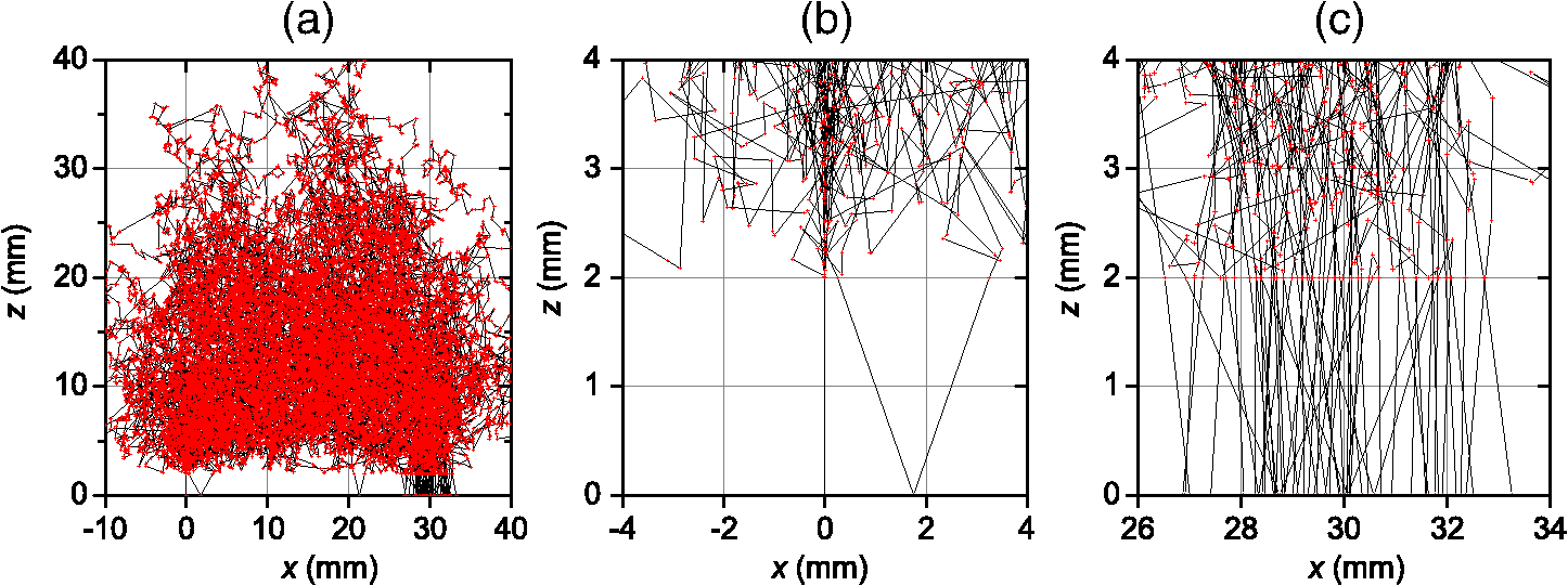 Similar investigations to those presented in Figs. 4 and 5 have been also done for Cell #1. For Cell #1, we can conclude that the time shape of the TPSF is not affected by the presence of the transparent windows and the length of all the photon trajectories increases by an average of 6.3 mm, independently of the photon arrival time, for both a collimated and a conical beam. This larger increase of the trajectory length with respect to the expected one (6 mm) is mainly due to the oblique crossing of the transparent windows. The major effect of these small transparent windows in Cell #1 results in a strong reduction of the field-of-view of the detection system. Figure 6 reports the trajectories of the first 50 detected photons at a 30-mm interfiber distance. In particular, none of the 50 trajectories crosses the input and the output transparent windows more than once. Again, the small dimensions of these windows prevents multiple crossings. Fig. 6Trajectories of the first 50 photons detected (a), in reflection geometry at 30-mm interfiber distance for Cell #1 and a collimated beam source. Also particulars of the input (b) and output (c) transparent windows are reported. None of 50 photons crosses the transparent windows more than once. The windows of the cell are 3-mm thick with a diameter.  If we compare Cell #2 to Cell #1, we note that the increase of the trajectory length in Cell #2 is larger (more than 10% of the expected 4 mm) and mainly due to multiple crossings, facilitated by the larger dimension of the transparent windows of Cell #2 (7 mm in diameter against 3 mm for Cell #1). It is worth pointing out that if completely transparent walls were used for the container, the propagation would be greatly different compared to the case of the black walls analyzed here, with large distortions of the temporal response as shown in Ref. 35. 4.Experiments4.1.Experimental SetupThe experiments were performed with a laboratory setup (Exp1) exhibiting high time resolution, as well as with a time-domain optical brain imager devised for clinical applications (Exp2, Exp3). In the setup Exp1, a supercontinuum laser SC500-6 with acousto-optic tunable filter (Fianium Ltd, Southampton, United Kingdom), operated at 800 nm and provided picosecond pulse trains with a repetition rate of 40.5 MHz. The TR reflectance was measured with a hybrid detector module HPM-100-50 and an SPC-134 system for time-correlated single-photon counting (both Becker&Hickl GmbH, Berlin, Germany). The source fiber was a 2-m-long graded-index fiber, whereas in the detection path a multimode fiber (length 2 m, diameter 1 mm, numerical aperture 0.39) was employed. The time-domain optical brain imager51 contained a picosecond diode laser system Sepia (PicoQuant GmbH, Berlin, Germany) and was equipped with two types of detector modules based on the fast photomultipliers R7400U-02 and H7422P-50 (Hamamatsu Photonics, Hamamatsu, Japan), respectively, for configurations Exp2 and Exp3. In all configurations, the initial count rate without absorber was adjusted to about . The collection time was for all measurements. 4.2.Experimental ResultsThe validation of the proposed inhomogeneous phantom was obtained by a comparison between time domain experimental results of absorption perturbations measured from the phantom and the results of the MC simulations. Indeed, the purpose of this comparison was not to validate the ER, but to show that the implemented phantom can really generate absorption perturbations of the expected values. A simple experiment is considered to be one that illustrates a basic application of an inhomogeneous phantom. A totally absorbing black PVC cylinder was suspended in the black PVC tank containing a water suspension of intralipid and ink (, ). The optical properties of the background diffusive liquid medium were determined with an uncertainty of less than 3% by previous calibration campaigns on intralipid and India ink.22,26,46 Making reference to an orthogonal coordinate system , we had on the plane the source fiber (placed at ) and the detection fiber (placed at and ). The cylinder was moved in the midplane between source and detector () with the help of a translation stage, parallel (in the direction) to the source and detection fibers with its axis aligned along the axis. Measurements were taken at various distances between the cylinder axis and the wall from 6 to 30 mm in 2-mm steps, and for the homogeneous case. Measurements were repeated with different cylinders (from 25 to ). The depth-dependent contrast for moments52 derived from the TPSFs measured with the setup Exp1 is shown in Fig. 7 for total photon counts and variance . The integration limits were chosen at 0.1% of the maximum value of the TPSF. Panels (a) and (b) report the relative contrast, , for total photon counts and differences in variance, , respectively, for scans of black PVC cylinders of various sizes. As expected, the contrast for total photon counts diminishes with depth and increases with the size of the inclusion. The same happens for the difference in variance, with the expected changing sign of variance contrast between 10 and 12 mm in depth. The results of the MC simulations for black spheres of equal volume are also shown. Agreement with the experimental results is very good. We stress that the experimental results and the MC results were plotted on the same absolute scale, and no fitting or amplitude matching was employed. The residual differences that can be noticed between simulations and experiments can be explained by possible systematic errors due to the uncertainty of positioning the cylinders in the direction () and to the different shapes of the inclusions, spheres in the MC simulations and cylinders in the experiments. In Fig. 8, the sensitivity plots based on a perturbation model pertaining to the same situation of Fig. 7 have been shown. Note that the changing sign of variance contrast in Fig. 7 is in accordance with the behavior of the related sensitivity plots of Fig. 8. The sign change of (i.e., ) around can be explained by considering the different effects of the absorbing cylinder on photon migration when it is placed at different depths in the medium. When the defect is located at shallow depths, it will mainly absorb photons that travel along relatively short paths. When the black cylinder is located more deeply in the medium, it mainly influences photons with long paths. In the former (latter) case, the variance in the inhomogeneous case will be larger (smaller) than in the homogeneous case. In Fig. 9, the results obtained with the three different setups, Exp1, Exp2, and Exp3, were plotted for the different cylinders at one particular depth together with the MC results. The results refer to the same contrasts as plotted in Figs. 7(a) and 7(b), i.e., relative contrast for total photon counts and difference in variance for the respective values of the maximum contrast magnitude. The results obtained with the three different experimental setups largely coincide. This is a consequence of the fact that the measurements based on differences in variance and other moments are virtually independent of the instrumental response function.52 On the other hand, the agreement between the three experimental datasets is an indication of the repeatability of the measurement. Fig. 7Panels (a) and (b) show a comparison between experiments and MC simulations pertaining to the relative contrast, , for total photon counts (a) and difference in variance, , (b) for scans of black PVC cylinders of various sizes, circles—measured, triangles—MC simulation.  Fig. 8Panels (a) and (b) show the relative (normalized to maximum) sensitivity maps related to point-like absorption perturbations for photon counts (a) and variance (b) for a source–detector separation of 3 cm, in the midplane between source and detector. The maps have been generated by using a diffusion model for small perturbations49 for , , and . The white arrows represent the scan plotted in Fig. 7. 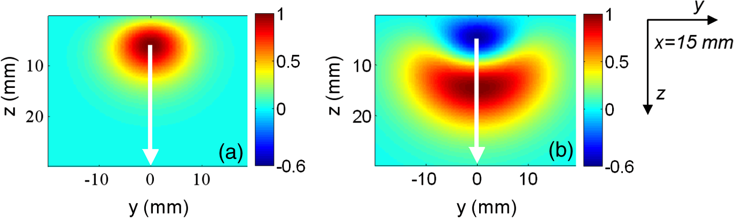 Fig. 9Relative contrast, , for total photon counts (a) for , and difference in variance, , (b) for , versus the absorption variation equivalent to the black PVC cylinders used as inclusions. Results obtained with all the three experimental setups are shown: triangles pertain to Exp1, circles pertain to Exp2, and diamonds pertain to Exp3. The squares are the MC simulations. The optical properties and the source–detector distance are the same as in Fig. 7.  Figure 9 displays the dependence of the contrast ( and ) on the inclusion in terms of the equivalent absorption change in a volume. These absorption changes were derived by means of the analytical relation between the volume of a black inclusion and the equivalent , which we provided in our previous paper.1 The dependence on shown in Fig. 9 turns out to be strongly nonlinear. This nonlinearity versus is not a consequence of the ER, but is a consequence of the physics of photon migration in the presence of strongly absorbing objects in general. It should be noted that the equivalent of the largest cylinder almost equals the tenfold background absorption, which is obviously very far from being a small absorption change. The contrast is linear in only for very small changes (for black inclusions with a volume ) for which the Born approximation is valid. The simple test done with this experiment, although it did not exhaust all the scenarios for the use of such an inhomogeneous phantom, is relevant since it testifies to the reliability and accuracy of the implemented phantom in reproducing absorption perturbations of any value and kind. The intensity and the kind of the absorption perturbation can be accurately determined by varying the position and volume of the black PVC inclusions. We finally point out that the effects of total absorption perturbations can be also simulated with the solvers recently proposed in Ref. 53 that calculates the perturbation with good accuracy and in a short time both for time and CW domains. These forward solvers and the implemented phantom described in this paper form a tool for studying imaging with biomedical optics instrumentation. For the forward calculations, we also mention the CW solver by Esposito et al.54 that shows excellent performances. 5.ConclusionsThe intent of this work was to provide a practical implementation and an experimental validation of the inhomogeneous phantom proposed in Ref. 1, where the basic concepts were presented. The practical implementation and realization of the phantom was achieved by making use of a liquid phantom accommodated inside a black scattering cell made of PVC. The totally absorbing inclusions were realized with manufactured cylinders made of black PVC. By adjusting the volume of the cylinders, it was possible to change the intensity of the absorption perturbation included inside the medium. The problems with this type of phantom realization have been investigated by means of numerical simulations. In particular, the following effects have been studied: (1) The perturbation introduced on photon migration by the transparent windows as an interface between medium and superficial optodes; (2) the perturbation introduced by the finite size of the phantom; (3) the shape effects of the totally absorbing inclusion; (4) the effects of reflections at the interface between inclusion and medium. The results of Sec. 3 show that the distortion on photon migration introduced by these effects is about 6% in total. The results of Fig. 7 finally show that the experiments accurately reproduce the MC simulations, so we can conclude that the implemented phantom translates the concepts described in Ref. 1 into practice. The phantom has been described for a single totally absorbing inclusion and for TR reflectance measurements. However, the phantom can be also used to simulate multiple inclusions, a layered structure (by inserting Mylar foils parallel to the surface to separate different regions55), or a combination of both layered structure and localized inclusions. Moreover, the cell can be easily adapted for transmission geometry: It is sufficient to equip the rear wall of the scattering cell with appropriate transparent windows for detection. Furthermore, if used for frequency-domain or CW experiments, we expect the same reliability and accuracy as we have shown for time-domain measurements. It is worth mentioning that the nEUROPt protocol was based on the phantom described here56 for the performance assessment of time-domain optical brain imagers. A set of eight identical kits were prepared and circulated among several laboratories. Up to now, eight different instruments have been thoroughly tested. A further step in the implementation proposed here is the realization of the same concept of an inhomogeneous phantom using a solid–solid structure. Work is in progress to provide the required reliability and accuracy of this alternative solution. Such solid–solid phantom construction may be preferred for the routine use of such tools, since re-preparation of the liquid component is necessary for any use of the phantom, whereas the liquid–solid implementation described in the present paper offers the best control of the optical properties of the background medium and the best flexibility. A final remark: The absorber used for the proposed phantom is India ink. Because it is a suspension of insoluble carbon particles in an aqueous medium, India ink also scatters light. Its albedo is, therefore, not equal to zero and thus it is difficult to measure the absorption coefficient with good accuracy. Furthermore, since particles tend to gather together, to obtain reproducible optical properties the dilutions must be sonicated before using. These difficulties can be overcome using nanofluids based on Carbon nanohorns. It has been shown57 that at near infrared wavelengths the albedo of these nanofluids is practically equal to zero, so that their absorption coefficient can be simply and precisely determined with spectrophotometric measurements. Furthermore, the absorption coefficient of these nanofluids is very stable over a long time and ultrasound application is not necessary. AcknowledgmentsAuthors are grateful to Danilo Marcucci for his effort in the realization of the scattering cell exploited for performing the measurements. The research leading to these results has received funding from the European Community’s Seventh Framework Programme [FP7/2007-2013] under grant agreement No. FP7-HEALTH-F5-2008-201076. The research leading to these results has also received funding from LASERLAB-EUROPE (grant agreement n. 284464, EC’s Seventh Framework Programme). ReferencesF. Martelliet al.,
“Phantoms for diffuse optical imaging based on totally absorbing objects, part 1: Basic concepts,”
J. Biomed. Opt., 18
(6), 066014
(2013). http://dx.doi.org/10.1117/1.JBO.18.6.066014 JBOPFO 1083-3668 Google Scholar
T. Durduranet al.,
“Diffuse optics for tissue monitoring and tomography,”
Rep. Prog. Phys., 73
(7), 076701
(2010). http://dx.doi.org/10.1088/0034-4885/73/7/076701 RPPHAG 0034-4885 Google Scholar
A. Torricelliet al.,
“Use of a nonlinear perturbation approach for in vivo breast lesion characterization by multiwavelength time-resolved optical mammography,”
Opt. Express, 11
(8), 853
–867
(2003). http://dx.doi.org/10.1364/OE.11.000853 OPEXFF 1094-4087 Google Scholar
P. Taroniet al.,
“Seven-wavelength time-resolved optical mammography extending beyond 1000 nm for breast collagen quantification,”
Opt. Express, 17
(18), 15932
–15946
(2009). http://dx.doi.org/10.1364/OE.17.015932 OPEXFF 1094-4087 Google Scholar
D. R. Leffet al.,
“Diffuse optical imaging of the healthy and diseased breast: a systematic review,”
Breast Cancer Res. Treat., 108
(1), 9
–22
(2008). http://dx.doi.org/10.1007/s10549-007-9582-z BCTRD6 Google Scholar
R. Choeet al.,
“Diffuse optical tomography of breast cancer during neoadjuvant chemotherapy: a case study with comparison to MRI,”
Breast Cancer Res. Treat., 32
(4), 1128
–1139
(2005). http://dx.doi.org/10.1118/1.1869612 BCTRD6 Google Scholar
P. Taroniet al.,
“Effects of tissue heterogeneity on the optical estimate of breast density,”
Biomed. Opt. Express, 3
(10), 2411
–2418
(2012). http://dx.doi.org/10.1364/BOE.3.002411 BOEICL 2156-7085 Google Scholar
E. Molteniet al.,
“Load-dependent brain activation assessed by time-domain functional near-infrared spectroscopy during a working memory task with graded levels of difficulty,”
J. Biomed. Opt., 17
(5), 056005
(2012). http://dx.doi.org/10.1117/1.JBO.17.5.056005 JBOPFO 1083-3668 Google Scholar
M. Buttiet al.,
“Effect of prolonged stimulation on cerebral hemodynamic: A time-resolved fNIRS study,”
Med. Phys., 36
(9), 4103
–4114
(2009). http://dx.doi.org/10.1118/1.3190557 MPHYA6 0094-2405 Google Scholar
M. N. Kimet al.,
“Noninvasive measurement of cerebral blood flow and blood oxygenation using near-infrared and diffuse correlation spectroscopies in critically brain-injured adults,”
Neurocrit. Care, 12
(2), 173
–180
(2010). http://dx.doi.org/10.1007/s12028-009-9305-x NCEACB 1541-6933 Google Scholar
R. A. De Blasiet al.,
“Cerebral and muscle oxygen saturation measurement by frequency-domain near-infra-red spectrometer,”
Med. Biol. Eng. Comput., 33
(2), 228
–230
(1995). http://dx.doi.org/10.1007/BF02523048 MBECDY 0140-0118 Google Scholar
B. J. SteinhoffG. HerrendorfC. Kurth,
“Ictal near infrared spectroscopy in temporal lobe epilepsy: a pilot study,”
Eur. J. Epilep., 5
(2), 97
–101
(1996). http://dx.doi.org/10.1016/S1059-1311(96)80101-4 Google Scholar
L. Spinelliet al.,
“Multimodality fnirs-eeg, fmri-eeg and tms clinical study on cortical response during motor task in adult volunteers and epileptic patients with movement disorders,”
in Proc. Biomedical Optics and 3-D Imaging,
BM4A.1
(2012). Google Scholar
A. H. Hielscheret al.,
“Frequency-domain optical tomographic imaging of arthritic finger joints,”
IEEE Trans. Instrum. Meas., 30
(10), 1725
–1736
(2011). http://dx.doi.org/10.1109/TMI.2011.2135374 IEIMAO 0018-9456 Google Scholar
B. C. WilsonM. S. Patterson,
“The physics, biophysics and technology of photodynamic therapy,”
Appl. Opt., 53
(9), R61
–R109
(2008). http://dx.doi.org/10.1088/0031-9155/53/9/R01 APOPAI 0003-6935 Google Scholar
J. HwangJ. C. Ramella-RomanR. Nordstrom,
“Introduction: feature issue on phantoms for the performance evaluation and validation of optical medical imaging devices,”
Biomed. Opt. Express, 3
(6), 1399
–1403
(2012). http://dx.doi.org/10.1364/BOE.3.001399 BOEICL 2156-7085 Google Scholar
M. FirbankD. T. Delpy,
“A design for a stable and reproducible phantom for use in near infra-red imaging and spectroscopy,”
Phys. Med. Biol., 38
(6), 847
–853
(1993). http://dx.doi.org/10.1088/0031-9155/38/6/015 PHMBA7 0031-9155 Google Scholar
U. Sukowskiet al.,
“Preparation of solid phantoms with defined scattering and absorption properties for optical tomography,”
Phys. Med. Biol., 41
(9), 1823
–1844
(1996). http://dx.doi.org/10.1088/0031-9155/41/9/017 PHMBA7 0031-9155 Google Scholar
M. Lualdiet al.,
“A phantom with tissue-like optical properties in the visible and near infrared for use in photomedicine,”
Laser Sur. Med., 28
(3), 237
–243
(2001). http://dx.doi.org/10.1002/(ISSN)1096-9101 LSMEDI 0196-8092 Google Scholar
A. Pifferiet al.,
“Performance assessment of photon migration instruments: the medphot protocol,”
Appl. Opt., 44
(11), 210414
(2005). http://dx.doi.org/10.1364/AO.44.002104 APOPAI 0003-6935 Google Scholar
L. G. Henyeyet al.,
“A soft deformable tissue-equivalent phantom for diffuse optical tomography,”
Phys. Med. Biol., 51
(21), 5581
–5590
(2006). http://dx.doi.org/10.1088/0031-9155/51/21/013 PHMBA7 0031-9155 Google Scholar
P. Di NinniF. MartelliG. Zaccanti,
“Intralipid: towards a diffusive reference standard for optical tissue phantoms,”
Phys. Med. Biol., 56
(2), N21
–N28
(2011). http://dx.doi.org/10.1088/0031-9155/56/2/N01 PHMBA7 0031-9155 Google Scholar
A. E. Cerussiet al.,
“Tissue phantoms in multicenter clinical trials for diffuse optical technologies,”
Biomed. Opt. Express, 3
(5), 966
–971
(2012). http://dx.doi.org/10.1364/BOE.3.000966 BOEICL 2156-7085 Google Scholar
G. Lamoucheet al.,
“Review of tissue simulating phantoms with controllable optical, mechanical and structural properties for use in optical coherence tomography,”
Biomed. Opt. Express, 3
(6), 1381
–1398
(2012). http://dx.doi.org/10.1364/BOE.3.001381 BOEICL 2156-7085 Google Scholar
J. P. Bouchardet al.,
“Reference optical phantoms for diffuse optical spectroscopy. part 1–error analysis of a time resolved transmittance characterization method,”
Opt. Express, 18
(11), 11495
–11507
(2010). http://dx.doi.org/10.1364/OE.18.011495 OPEXFF 1094-4087 Google Scholar
L. Spinelliet al.,
“Determination of reference values for optical properties of liquid phantoms based on Intralipid and India ink,”
Biomed. Opt. Express, 5
(7), 2037
–2053
(2014). http://dx.doi.org/10.1364/BOE.5.002037 BOEICL 2156-7085 Google Scholar
B. W. PogueM. S. Pattersona,
“Review of tissue simulating phantoms for optical spectroscopy, imaging and dosimetry,”
J. Biomed. Opt., 11
(4), 041102
(2006). http://dx.doi.org/10.1117/1.2335429 JBOPFO 1083-3668 Google Scholar
H. Jianget al.,
“Frequency-domain optical image reconstruction in turbid media: an experimental study of single-target detectability,”
Appl. Opt., 36
(1), 52
–63
(1997). http://dx.doi.org/10.1364/AO.36.000052 APOPAI 0003-6935 Google Scholar
J. P. Culveret al.,
“Three-dimensional diffuse optical tomography in the parallel plane transmission geometry: evaluation of a hybrid frequency domain/continuous wave clinical system for breast imaging,”
Med. Phys., 30
(2), 235
–247
(2003). http://dx.doi.org/10.1118/1.1534109 MPHYA6 0094-2405 Google Scholar
R. Cubedduet al.,
“Time-resolved imaging on a realistic tissue phantom: and images versus time-integrated image,”
Appl. Opt., 35
(22), 4533
–4540
(1996). http://dx.doi.org/10.1364/AO.35.004533 APOPAI 0003-6935 Google Scholar
S. Carraresiet al.,
“Accuracy of a perturbation model to predict the effect of scattering and absorbing inhomogeneities on photon migration,”
Appl. Opt., 40
(25), 4622
–4632
(2001). http://dx.doi.org/10.1364/AO.40.004622 APOPAI 0003-6935 Google Scholar
R. Cubedduet al.,
“A solid tissue phantom for photon migration studies,”
Phys. Med. Biol., 42
(10), 1971
–1979
(1997). http://dx.doi.org/10.1088/0031-9155/42/10/011 PHMBA7 0031-9155 Google Scholar
J. C. Hebdenet al.,
“An electrically-activated dynamic tissue-equivalent phantom for assessment of diffuse optical imaging systems,”
Phys. Med. Biol., 53
(2), 329
–337
(2008). http://dx.doi.org/10.1088/0031-9155/53/2/002 PHMBA7 0031-9155 Google Scholar
A. Gibsonet al.,
“Optical tomography of a realistic neonatal head phantom,”
Appl. Opt., 42
(16), 3109
–3116
(2003). http://dx.doi.org/10.1364/AO.42.003109 APOPAI 0003-6935 Google Scholar
S. Del BiancoF. MartelliG. Zaccanti,
“Effect of a clear layer at the surface of a diffusive medium on measurements of transmittance and reflectance,”
Opt. Express, 12
(22), 5510
–5517
(2004). http://dx.doi.org/10.1364/OPEX.12.005510 OPEXFF 1094-4087 Google Scholar
R. Barbouret al.,
“programmable laboratory testbed in support of evaluation of functional brain activation and connectivity,”
IEEE Trans. Neural. Syst. Rehabil. Eng., 20
(2), 170
–183
(2012). http://dx.doi.org/10.1109/TNSRE.2012.2185514 ITNSB3 1534-4320 Google Scholar
D. A. Boaset al.,
“Scattering of diffuse photon density waves by spherical inhomoheneities within turbid media: analytical solution and applications,”
Proc. Natl. Acad. Sci. U.S.A., 91
(11), 4887
–4891
(1994). http://dx.doi.org/10.1073/pnas.91.11.4887 PNASA6 0027-8424 Google Scholar
J. C. J. PaasschensG. W. Hooft,
“Influence of boundaries on the imaging of objects in turbid media,”
J. Opt. Soc. Am. A, 15
(7), 1797
–1812
(1998). http://dx.doi.org/10.1364/JOSAA.15.001797 JOAOD6 0740-3232 Google Scholar
A. Takatsukiet al.,
“Absorber’s effect projected directly above improves spatial resolution in near infrared backscattered imaging,”
Jpn. J. Physiol., 54
(1), 79
–86
(2004). http://dx.doi.org/10.2170/jjphysiol.54.79 JJPHAM 0021-521X Google Scholar
A. Pifferiet al.,
“Time-resolved diffuse reflectance using small source-detector separation and fast single-photon gating,”
Phys. Rev. Lett., 100
(13), 138101
(2008). http://dx.doi.org/10.1103/PhysRevLett.100.138101 PRLTAO 0031-9007 Google Scholar
Q. Zhaoet al.,
“Functional tomography using a time-gated ICCD camera,”
Biomed. Opt. Express, 2
(3), 705
–716
(2011). http://dx.doi.org/10.1364/BOE.2.000705 BOEICL 2156-7085 Google Scholar
F. MartelliG. Zaccanti,
“Calibration of scattering and absorption properties of a liquid diffusive medium at NIR wavelengths. CW method,”
Opt. Express, 15
(2), 486
–500
(2007). http://dx.doi.org/10.1364/OE.15.000486 OPEXFF 1094-4087 Google Scholar
R. MichelsF. FoschumA. Kienle,
“Optical properties of fat emulsions,”
Opt. Express, 16
(8), 5907
–5925
(2008). http://dx.doi.org/10.1364/OE.16.005907 OPEXFF 1094-4087 Google Scholar
F. FoschumA. Kienle,
“Optimized goniometer for determination of the scattering phase function of suspended particles: simulations and measurements,”
J. Biomed. Opt., 18
(8), 085002
(2013). http://dx.doi.org/10.1117/1.JBO.18.8.085002 JBOPFO 1083-3668 Google Scholar
B. Aernoutset al.,
“Supercontinuum laser based optical characterization of intralipid phantoms in the 500–2250 nm range,”
Opt. Express, 21
(26), 32450
–32467
(2013). http://dx.doi.org/10.1364/OE.21.032450 OPEXFF 1094-4087 Google Scholar
P. Di NinniF. MartelliG. Zaccanti,
“The use of India ink in tissue-simulating phantoms,”
Opt. Express, 18
(26), 26854
–26865
(2010). http://dx.doi.org/10.1364/OE.18.026854 OPEXFF 1094-4087 Google Scholar
L. Spinelliet al.,
“Calibration of scattering and absorption properties of a liquid diffusive medium at NIR wavelengths. time-resolved method,”
Opt. Express, 15
(11), 6589
–6604
(2007). http://dx.doi.org/10.1364/OE.15.006589 OPEXFF 1094-4087 Google Scholar
P. Di Ninniet al.,
“Fat emulsions as diffusive reference standards for tissue simulating phantoms?,”
Appl. Opt., 51
(30), 7176
–7182
(2012). http://dx.doi.org/10.1364/AO.51.007176 APOPAI 0003-6935 Google Scholar
F. Martelliet al., Light Propagation through Biological Tissue and Other Diffusive Media, SPIE Press, Bellingham, Washington
(2010). Google Scholar
A. Sassaroliet al.,
“Monte Carlo procedure for investigating light propagation and imaging of highly scattering media,”
Appl. Opt., 37
(31), 7392
–7400
(1998). http://dx.doi.org/10.1364/AO.37.007392 APOPAI 0003-6935 Google Scholar
H. Wabnitzet al.,
“Time-resolved near-infrared spectroscopy and imaging of the adult human brain,”
Adv. Exp. Med. Biol., 662 143
–148
(2010). http://dx.doi.org/10.1007/978-1-4419-1241-1 AEMBAP 0065-2598 Google Scholar
A. Liebertet al.,
“Evaluation of optical properties of highly scattering media by moments of distributions of times of flight of photons,”
Appl. Opt., 42
(28), 5785
–5792
(2003). http://dx.doi.org/10.1364/AO.42.005785 APOPAI 0003-6935 Google Scholar
A. Sassaroliet al.,
“Forward solvers for photon migration in the presence of highly and totally absorbing objects embedded inside diffusive media,”
J. Opt. Soc. Am. A, 31
(3), 460
–469
(2014). http://dx.doi.org/10.1364/JOSAA.31.000460 JOAOD6 0740-3232 Google Scholar
R. EspositoF. MartelliS. De Nicola,
“Closed-form solution of the steady-state photon diffusion equation in the presence of absorbing inclusions,”
Opt. Lett., 39
(4), 826
–829
(2014). http://dx.doi.org/10.1364/OL.39.000826 OPLEDP 0146-9592 Google Scholar
S. Del Biancoet al.,
“Liquid phantom for investigating light propagation through layered diffusive media,”
Opt. Express, 12
(10), 2102
–2111
(2004). http://dx.doi.org/10.1364/OPEX.12.002102 OPEXFF 1094-4087 Google Scholar
A. Wabnitzet al.,
“Performance assessment of time-domain optical brain imagers: a multi-laboratory study,”
Proc. SPIE, 8583 85830L
(2013). http://dx.doi.org/10.1117/12.2002438 PSISDG 0277-786X Google Scholar
E. Saniet al.,
“Carbon nanohorn-based nanofluids: characterization of the spectral scattering albedo,”
Nanoscale Res. Lett., 7 96
(2012). http://dx.doi.org/10.1186/1556-276X-7-96 1556-276X Google Scholar
BiographyFabrizio Martelli received his master’s degree from the Physics Department of the University of Florence, Italy, in 1996, and his PhD degree from the University of Electro-communications, Tokyo, Japan, in 2002. He is currently with the Physics and Astronomy Department of the University of Florence, Italy. His major topics are light propagation through diffusive media and the development of inversion procedures to retrieve the optical properties of diffusive media from time-resolved and spatially resolved measurements. |


