|
|
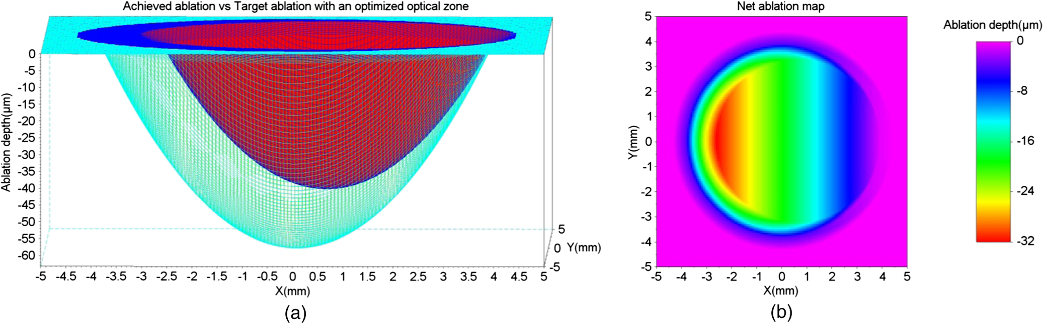
1.IntroductionThe realm of refractive surgery is advancing at a rapid pace.1 Conventional laser-assisted in situ keratomileusis (LASIK) procedures brought a revolution in surgically treating the lower-order aberrations (myopia, hyperopia, and astigmatism) of the eye.2 With the advent of aberrometry techniques capable of calculating the wavefront of an individual eye,3 customized wavefront-guided treatments brought a new revolution by extending the refractive treatment to higher-order aberrations (HOAs) like coma and trefoil.4 This individualized treatment is aimed at improving not only the quantity of vision (based on Snellen tests), but also the quality of how well one can see (i.e., visual acuity measured in terms of contrast sensitivity and fine vision).5 Choosing the correct optical zone (OZ) size to pupil ratio has a significant impact on the treatment outcomes.6 An incorrect balance could result in the treatment being ineffective in removing the HOAs, instead inducing additional HOAs during the procedure.7 In comparison to conventional LASIK, wavefront-guided treatments have shown less increase in coma and HOA for a similar or smaller OZ size.8 Complications may also arise because of a decentered ablation,9 resulting from human or mechanical errors. Such an event results in over-/ or under-corrections at different locations in the cornea, inducing HOAs. The outcome is patients complaining of seeing glares and halos after the procedure. Secondary refractive procedures can be planned to correct the residual refractive error and to induce the centration, eventually improving the visual quality of the patients. Customized wavefront-guided treatments are often used to design such retreatment procedures.10 These treatments have proven effective in reducing lower-/ and higher-order aberrations, expanding OZs, and improving subjective reports of adverse aberration sequelae, such as glare and halos.11 However, due to the limitations of wavefront sensors in precisely measuring very large aberrations, some extreme cases may suffer when retreated with wavefront-guided treatments.12–18 Furthermore, patients with clinical limitations, like critical residual corneal thickness, can always benefit from a more tissue-saving approach. We propose a nonwavefront-guided simple, inexpensive, and robust method for planning a repeat treatment in such extreme cases. This method manipulates only the lower-order refractive errors of the eye. The idea is to leave the visual print of the cornea in its original form and to treat only the components most affecting the normal vision (lower-order refractive errors). Therefore, new HOAs are not induced, since they are not manipulated at all in the procedure. Similar ablation profiles (commonly known as aberration neutral profiles) are popular today in planning primary refractive procedures. Our motivation is to manipulate the OZ to induce the centration, to save the most important components of normal vision with minimal tissue ablation, and to bring the HOA (till the third order) back to the pre-op status. We calculate the ablation maps based on the results achieved in the first refractive procedure and the intended goals (refractive correction with centration) of the repeat procedure. Based on these ablation maps, we calculate the net ablation map for a repeat treatment. 2.Materials and MethodsWe calculated two ablation maps. The first map is the reconstruction of the ablation performed in the primary refractive procedure, based on the achieved results. We call this map the achieved ablation. The second ablation map targets the original refractive error with an OZ larger than the OZ achieved in the first refractive procedure (i.e., the OZ of the achieved ablation). We call this map the target ablation. The optimum OZ size of the target ablation is calculated by comparing the target and achieved ablations. The net ablation map for the repeat procedure is calculated as the difference of the target and the achieved ablations. Please note that there are no real patients involved, and this study is based on simulations only. We subsequently present some examples of simulation cases to explain the technique. This method is independent of the shape of ablation profiles and the kind of refractive procedure performed during the primary treatment. We worked with simple parabolic profiles (paraxial approximation of the Munnerlynn profiles19), but this method can be easily extended to more general profiles (aspheric20 or wavefront optimized21). We begin with estimating the achieved ablation. The refractive components (sphere, cylinder, and axis) are calculated as the difference of the originally planned and the currently measured refractions (achieved after the first refractive procedure). Alternatively, the achieved refractive correction can be objectively calculated as the vectorial difference between preoperative and postoperative K-readings.22 Please note that we only consider the lower-order components of refractive error irrespective of the kind of procedure performed in the first attempt. The effect of decentration achieved in the first refractive procedure is also included in the calculations. This decentration (and the achieved OZ) can be obtained from either a single postoperative topography (by analyzing the flattened or steepened area and the size of the ring surrounding the ablation in a local curvature map) or from a preoperative-to-postoperative differential map. Based on this data (achieved refractive error, achieved OZ, and achieved decentration), the achieved ablation is calculated. In the next step, we calculate the target ablation with the originally attempted refractive correction (sphere, cylinder, and axis), achieved OZ, and complete centration. We optimize the target ablation by comparing it with the achieved ablation. Figure 1 illustrates this comparison. We simulate a parabolic ablation profile for a myopic case ( originally planned) with an achieved over-correction after the first refractive procedure () and a decentration of 0.6 mm. The red color on the map represents the achieved ablation, whereas the green color on the map represents the target ablation designed with the same OZ but with adequate correction and centration. As clearly seen from Fig. 1, the two ablation profiles cross each other representing an unfeasible ablation. In a repeat procedure, the ablation can only be effective and feasible at the locations where tissue remained after the primary procedure. Fig. 1Cross-sectional view of the achieved ablation (red) versus the target ablation (green) for a retreatment procedure. Both ablation maps are designed for an optical zone (OZ) of 6.5 mm. The region where the two ablation maps cut each other represents the regions of unfeasible ablation.  To solve this problem of unfeasible ablation, we manipulate the OZ size of the target ablation in a way that the target ablation completely envelops the achieved ablation while maintaining its shape. We iteratively (in steps of 0.1 mm) expand the OZ of the target ablation until the ablation depth at all points on the target ablation is at least equal to the achieved ablation. In our algorithm, we select the minimum OZ size fulfilling the condition: A transition zone 1 or 2 mm larger than the selected OZ is used for myopia and hyperopia, respectively. We imposed an upper limit to the total number of iterations (hence, the maximum OZ of the target ablation). If the condition represented in Eq. (1) is not fulfilled until the last iteration, the target ablation is calculated using the maximum optical and transition zones (set by the upper limit) and shifted down (to ensure that all points remove the tissue) according to the calculated shift in the -axis as where the target ablation is calculated using the maximum optical and transition zones set by the upper limit. In our experiments, we restricted the optical and transition zones to 9 and 10 mm, respectively, for myopic cases. For hyperopic cases, we restricted the optical and transition zones to 8 and 10 mm, respectively. Such high limits were set to simulate extreme cases of decentration.The difference between the target (centered and modulated, with a larger OZ) and the achieved (decentered, over- or under-corrected) ablations is the net ablation map. Ablating the difference of the two ablation maps means removing only the tissue needed to maintain the shape of the target ablation. Although increasing the OZ always implies increasing the ablation depth, this approach minimizes the ablation depth in the repeat treatment procedure by purely basing the ablation map on the difference of a proposed oversized ideal ablation (target ablation) and an initial decentered ablation (achieved ablation). In this approach, we ensure that at least one point on the net ablation map corresponds to a zero ablation depth (i.e., no ablation). To completely correct decentration or refractive error in a retreatment procedure, one cannot ablate lesser tissue using any other kind of treatment method. Using a different OZ than the one proposed by this method could mean either partially correcting the problem or correcting the problem only in the central region (with the -shift). We simulated our algorithm in SCILAB software version 5.4.1.23 Several cases of myopia and hyperopia (with or without decentration) were tested (Table 1). Table 1We simulate the most common problems in refractive surgery for myopia and hyperopia.
For our experiments, we used an achieved OZ size of 6.5 mm. This value is typical for corneal laser refractive surgery. Also, over-/under-corrections in our examples are representative of the state-of-the-art in refractive surgery. Decentration of 0.6 mm is rather uncommon and only taken for illustrative purposes. 3.ResultsWe present the results of our simple numerical approach with three-dimensional surface maps comparing the achieved ablation (red) with the target ablation (green) for each test case (Table 1). We also present the net ablation map with a two-dimensional rainbow colored map. The color scale represents the ablation depth in micrometers. 3.1.Case 1The achieved ablation was without any decentration; therefore, the target ablation is much symmetric to the achieved ablation. The enlarged OZ (and the net ablation) only corrects the refractive error (Fig. 2). 3.4.Case 4In this case, the condition in Eq. (1) is not satisfied till the maximum iteration; therefore, the target ablation is calculated with a -shift of , as seen in Fig. 5. Fig. 5(a) Achieved ablation (red) versus target ablation (green) with an optimized enlarged OZ. For this case, the originally planned refraction was , while the achieved ablation was , with a decentration of 0.6 mm. (b) Cross-sectional view of the ablation maps. (c) Net ablation map resembling the correction of coma and spherical aberrations. 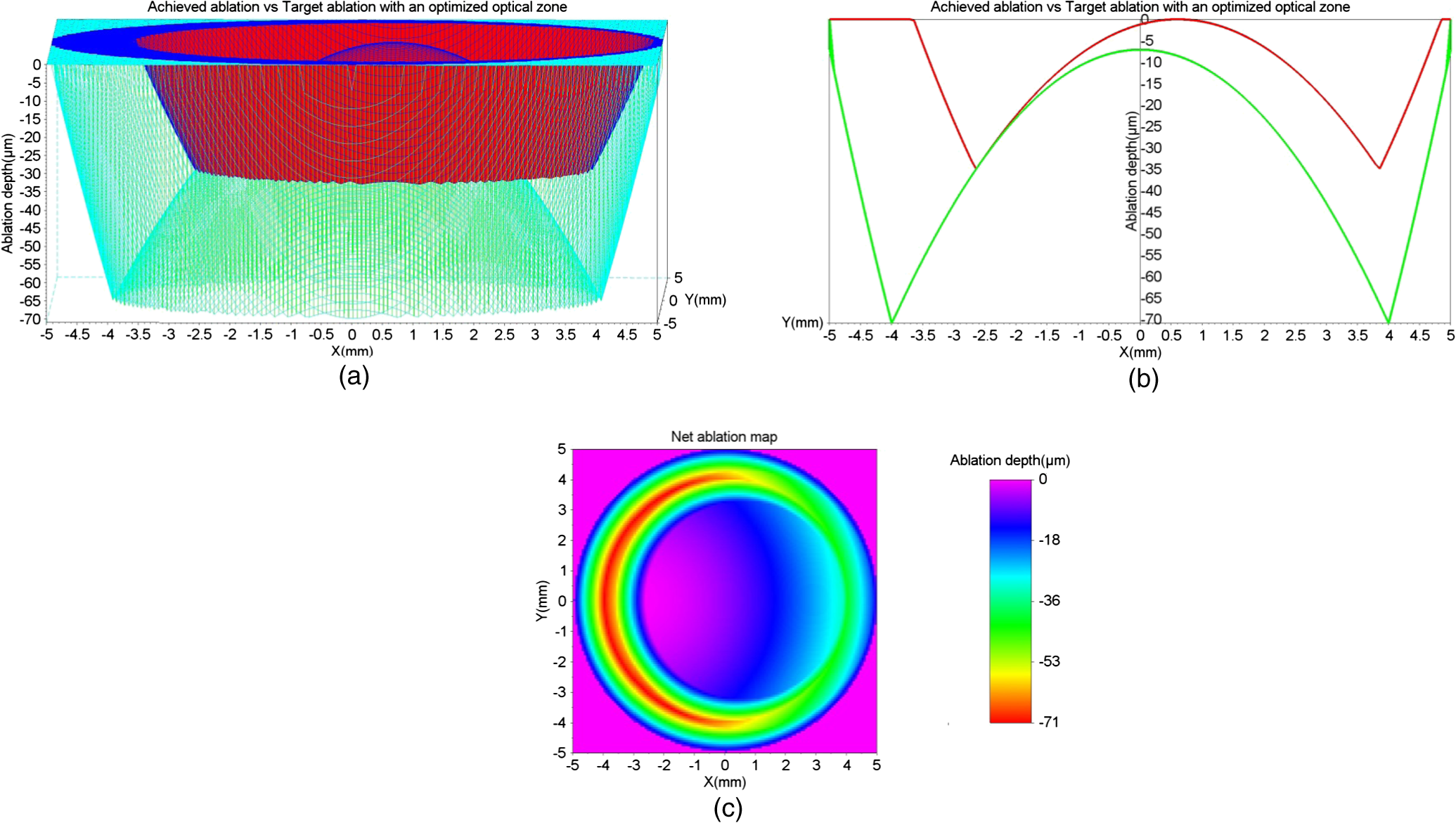 A seventh-order Zernike fit of the net ablation map was performed for all cases. Table 2 presents the relevant nonzero Zernike coefficient terms, the -shift, and the optimum optical and transition zones for each experimental case. Please note that these Zernike coefficients represent the net ablation map and not the postretreatment corneal shape after the proposed procedure. The Zernike fit only serves the purpose of qualitatively describing the “numerical ablation” (net ablation map) in familiar terms (Zernike coefficients) for the optical and visual sciences community. Table 2Net ablation map for the tested cases.
To analyze the stability of our algorithm against the uncertainty in registering the physical quantities that form the basis of our methods, we performed a perturbation analysis on case 3 presented in Table 1. We tested the effect of uncertainty in measuring the originally planned refraction, the achieved topographic OZ, and the decentration offset. The tested scenarios are presented in Table 3. Table 3Perturbation analysis based on the uncertainty in measuring the originally planned refraction, the achieved topographic OZ, and the decentration offset.
Figure 6 presents the net ablation map for the tested scenarios along with a difference of the net ablation maps for each varying parameter. The difference of the net ablation maps from scenarios A and B is aimed at correcting the refractive error, from scenarios C and D is aimed at widening the achieved OZ, whereas scenarios E and F are aimed at achieving the centration. We observed robustness in the algorithm in the presence of induced variations. Fig. 6The net ablation map obtained for different scenarios tested in the perturbation analysis. Left column (a and b) represents uncertainty in originally planned refraction. Center column (c and d) represents uncertainty in achieved optical zone. Right column (e and f) represents uncertainty in decentration. Top row (a, c, and e) represents the lowest values, middle row (b, d, and f) represents highest values, bottom row represents the differences. 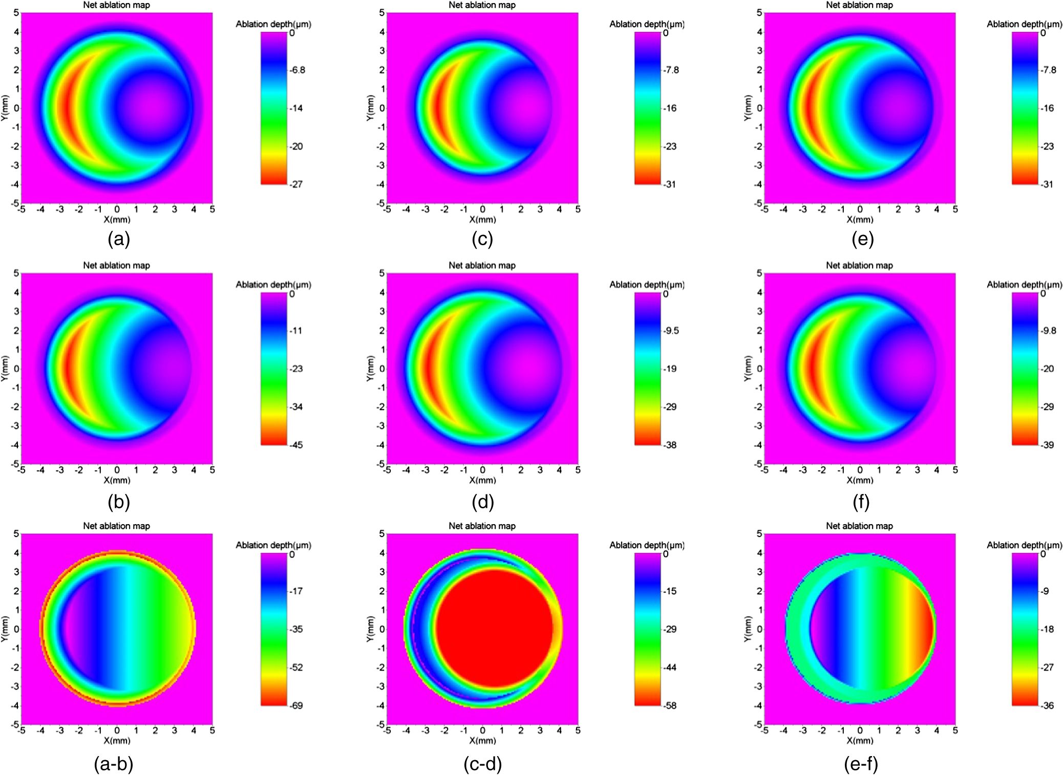 Further, to the presented results, we simulated two extreme cases. The first extreme case was originally a myope (), whose outcome from a post-op refraction was after the first refractive procedure (achieved refraction of ) with an achieved OZ of 6.0 mm and a decentration of 0.9 mm at 270 deg. The second extreme case was originally a myope (), whose outcome from a post-op refraction was after the first refractive procedure (achieved refraction of ) with an achieved OZ of 6.4 mm and a decentration of 0.6 mm at 0 deg. For both these extreme cases, we calculated a net ablation map aimed at achieving emmetropia with centration using the method of OZ expansion. These net ablation maps were compared with the corneal wavefront aberration maps directly derived from the topographies acquired with the Keratron SCOUT (Optikon, Rome, Italy). Figure 7 presents this comparison for the first and second extreme cases. The difference of the two wavefront maps is also presented for each case (Fig. 7). The qualitative similarity in the global maps and low deviations in the difference maps show the promising comparability between the results from the presented method and a well-established market product. Fig. 7Comparison of the topographic results from SCOUT with the synthetically generated results for extreme cases of myopia. Left: extreme case 1, originally attempted, achieved refraction of , with a 6.0 mm OZ and 0.9 mm of decentration at 270 deg. Right: extreme case 2, originally attempted, achieved refraction of , with a 6.4 mm OZ and 0.6 mm of decentration at 0 deg.  4.DiscussionUnder- or over-corrections are common problems in refractive procedures.24 Also, decentration due to human or mechanical errors cannot be avoided10 at subclinical levels.9 Eyes with decentered ablations show a significantly higher magnitude of induced aberrations and lower uncorrected distance visual acuity than eyes with well-centered ablations.25 Smaller OZs achieved in refractive procedures pose post-op problems like night vision disturbance, reduced contrast sensitivity, and ghosting. In such cases, wavefront-guided retreatment is often performed.12 However, critical residual corneal thickness and inaccurate wavefront measurement present as limitations in extreme cases. Improving the wavefront-sensing techniques is the ideal solution for such extreme cases. However, we approach this problem with a different perspective, a simple and easy-to-implement alternative approach that spares tissue and is focused on centering or enlarging the OZ while removing the lower-order residual aberrations. The implications of the method can be speculative. We discuss these implications purely based on the expected effect of ablating the net ablation map calculated by using this approach. We observe that the net ablation map is not the final result, but only one optical component that has to be coupled with others. However, at this stage of the theoretical approach, we can only speculate based on the available knowledge on laser ablation. We acknowledge that this approach considers only the lower-order aberrations and is not optimally suited to correct the decentration in higher-order wavefront-guided ablations. However, a decentered ablation aimed at higher-order terms would couple to the respective lower-order terms. In addition, the Zernike weights become lower with an increasing order. Consequently, the net ablation map shall manipulate the components of vision most affected by a decentered ablation. The factors that cause a difference between the current and the intended surgeries in the primary procedure continue to be present and to influence the repeat treatment. However, these factors are proportional to the goals of the intended surgery. In a repeat procedure, the intended surgery is aimed at a significantly lower-refractive error comparatively. Nevertheless, the effect of these influencing factors cannot be completely compensated for in a repeat procedure using any known surgical technique. Furthermore, we assumed a regular ablation profile considering three parameters only, under- or over-correction, decentration, and achieved OZ (macro-irregularities), without considering any micro-irregularity from the first refractive procedure. Table 2 shows that the ablation aimed at enlarging the OZ indirectly implied correcting mainly for spherical aberration and at correcting the decentration indirectly implied correcting mainly for coma. These results show the qualitative similarity to the results of customized treatments and the implication of OZ sizes on HOA.26 Along similar lines, in cases of astigmatism, correcting decentration would indirectly imply correcting trefoil.26,27 This method may be specially suited for over-corrections, since topographers and aberrometers may not correctly reconstruct the optical systems for such cases due to the strong gradient between myopic and hyperopic areas. The only requirements to apply this method are good pre- and post-op topographies from the first refractive procedure. In the extreme case, just a good single post-op topography acquired with any topographer may be a sufficient starting point. Different approaches have been used to tackle the problem of corneal thickness in critical cases. Hafezi et al. explored a two-step procedure to enlarge small OZs in high myopic cases after photorefractive keratectomy (PRK). In the first step, they performed a clear lens exchange aiming at hyperopia. In the second step, they performed topography-guided customized (PRK) with marked enlargement of the OZ.28 Lafond et al. described a retreatment technique using a combination of large-diameter myopic and hyperopic excimer laser ablations (of a near-equivalent dioptre value) to enlarge previous small ablation zones without altering the refractive result obtained by the initial surgery.29 Wu et al. found that the topography-guided ablation with a LaserSight excimer laser is effective to correct the decentered ablation. However, the retreated eye still remained inferior to the eye with originally centered ablation in terms of corneal optical quality or visual performance.30 Laser ablations with combined myopic and hyperopic profiles have been used to treat the induced decentration. Lafond et al. found that a combination of myopic and hyperopic ablations (of an equivalent dioptric magnitude), each decentered 180-deg apart and was effective in treating previously induced decentration. They observed minimal alteration of the refractive status compared with the results of the initial surgery.31 Lin and Manche evaluated the custom-contoured ablation pattern (C-CAP) method as a tool for providing customized laser ablations for decentered ablations based on corneal topography data. They concluded that the C-CAP method was an effective tool to address untreatable postsurgical decentration.32 Technological advances are constantly explored in wavefront-sensing techniques and will hopefully present a solution to the current problems posed in retreatment procedures. However, the presented method can serve as a ready-to-use alternative to wavefront-guided retreatments with its inherent benefits and limitations.We hope that with this model we can explore changing the paradigm from repair to simply “just complete an oversized ideal ablation.” AcknowledgmentsThe article has not been presented at any meeting. The authors did not receive any financial support from any public or private sources. The authors have no financial or proprietary interest in a product, method, or material described herein. But they both are employees of SCHWIND eye-tech-solutions. The article represents the personal views of the authors and was not written as a work for hire within the terms of the author’s employment with SCHWIND eye-tech-solutions. The work described in the article itself (as opposed to the work done writing the article) was conducted as part of the author’s work for SCHWIND eye-tech-solutions. Content attributed to the authors was vetted by the standard SCHWIND eye-tech-solutions approval process for third-party publications. ReferencesC. McAlinden,
“Corneal refractive surgery: past to present,”
Clin. Exp. Optom., 95
(4), 386
–398
(2012). http://dx.doi.org/10.1111/cxo.2012.95.issue-4 0816-4622 Google Scholar
C. R. MunnerlynS. J. KoonsJ. Marshall,
“Photorefractive keratectomy: a technique for laser refractive surgery,”
J. Cataract Refract. Surg., 14
(1), 46
–52
(1988). http://dx.doi.org/10.1016/S0886-3350(88)80063-4 JCSUEV 0886-3350 Google Scholar
J. Lianget al.,
“Objective measurement of wave aberrations of the human eye with the use of a Hartmann-Shack wave-front sensor,”
J. Opt. Soc. Am. A Opt. Image Sci. Vis., 11
(7), 1949
–1957
(1994). http://dx.doi.org/10.1364/JOSAA.11.001949 JOAOD6 0740-3232 Google Scholar
M. MrochenM. KaemmererT. Seiler,
“Wavefront-guided laser in situ keratomileusis: early results in three eyes,”
J. Refract. Surg., 16
(2), 116
–121
(2000). JRSUEY 0883-0444 Google Scholar
E. J. Fernándezet al.,
“Adaptive optics visual simulator,”
J. Refract. Surg., 18
(5), S634
–S638
(2002). JRSUEY 0883-0444 Google Scholar
J. M. Davidorfet al.,
“Effect of varying the optical zone diameter on the results of hyperopic laser in situ keratomileusis,”
Ophthalmology, 108
(7), 1261
–1265
(2001). http://dx.doi.org/10.1016/S0161-6420(01)00588-7 OPANEW 0743-751X Google Scholar
J. BührenC. KühneT. Kohnen,
“Influence of pupil and optical zone diameter on higher-order aberrations after wavefront-guided myopic LASIK,”
J. Cataract Refract. Surg., 31
(12), 2272
–2280
(2005). http://dx.doi.org/10.1016/j.jcrs.2005.10.023 JCSUEV 0886-3350 Google Scholar
D. H. LeeO. R. OhD. Z. Reinstein,
“Conservation of corneal tissue with wavefront-guided laser in situ keratomileusis,”
J. Cataract Refract. Surg., 31
(6), 1153
–1158
(2005). http://dx.doi.org/10.1016/j.jcrs.2004.12.039 JCSUEV 0886-3350 Google Scholar
M. Mrochenet al.,
“Increased higher-order optical aberrations after laser refractive surgery: a problem of subclinical decentration,”
J. Cataract Refract. Surg., 27
(3), 362
–369
(2001). http://dx.doi.org/10.1016/S0886-3350(00)00806-3 JCSUEV 0886-3350 Google Scholar
M. Mrochenet al.,
“Aberration-sensing and wavefront-guided laser in situ keratomileusis,”
J. Refract. Surg., 18
(4), 418
–429
(2002). JRSUEY 0883-0444 Google Scholar
J. A. HiattC. N. GrantB. S. Wachler,
“Complex wavefront-guided retreatments with the Alcon CustomCornea platform after prior LASIK,”
J. Refract. Surg., 22
(1), 48
–53
(2006). JRSUEY 0883-0444 Google Scholar
M. Mrochenet al.,
“Aberration-sensing and wavefront-guided laser in situ keratomileusis: management of decentered ablation,”
J. Refract. Surg., 18
(4), 418
–429
(2002). JRSUEY 0883-0444 Google Scholar
A. CervinoS. L. HoskingM. C. Dunne,
“Operator-induced errors in Hartmann-Shack wavefront sensing: model eye study,”
J. Cataract Refract. Surg., 33
(1), 115
–121
(2007). http://dx.doi.org/10.1016/j.jcrs.2006.09.025 JCSUEV 0886-3350 Google Scholar
R. R. Krueger,
“Corneal topography vs ocular wavefront sensing in the retreatment of highly aberrated post-surgical eyes,”
J. Refract. Surg., 22
(4), 328
–330
(2006). JRSUEY 0883-0444 Google Scholar
R. A. ApplegateJ. D. MarsackE. J. Sarver,
“Noise in wavefront error measurement from pupil center location uncertainty,”
J. Refract. Surg., 26
(10), 796
–802
(2010). http://dx.doi.org/10.3928/1081597X-20100921-05 JRSUEY 0883-0444 Google Scholar
A. JinabhaiC. O’DonnellH. Radhakrishnan,
“A comparison between subjective refraction and aberrometry-derived refraction in keratoconus patients and control subjects,”
Curr. Eye Res., 35
(8), 703
–714
(2010). http://dx.doi.org/10.3109/02713681003797921 CEYRDM 0271-3683 Google Scholar
S. Marcos,
“Aberrometry: basic science and clinical applications,”
Bull. Soc. Belge. Ophtalmol.,
(302), 197
–213
(2006). Google Scholar
N. Maedaet al.,
“Wavefront aberrations measured with Hartmann-Shack sensor in patients with keratoconus,”
Ophthalmology, 109
(11), 1996
–2003
(2002). http://dx.doi.org/10.1016/S0161-6420(02)01279-4 OPANEW 0743-751X Google Scholar
D. GatinelT. Hoang-XuanD. T. Azar,
“Determination of corneal asphericity after myopia surgery with the excimer laser: a mathematical model,”
Invest. Ophthalmol. Vis. Sci., 42
(8), 1736
–1742
(2001). IOVSDA 0146-0404 Google Scholar
D. Gatinelet al.,
“Analysis of customized corneal ablations: theoretical limitations of increasing negative asphericity,”
Invest. Ophthalmol. Vis. Sci., 43
(4), 941
–948
(2002). IOVSDA 0146-0404 Google Scholar
M. Mrochenet al.,
“Wavefront-optimized ablation profiles: theoretical background,”
J. Cataract Refract. Surg., 30
(4), 775
–785
(2004). http://dx.doi.org/10.1016/j.jcrs.2004.01.026 JCSUEV 0886-3350 Google Scholar
D. DeOrtuetaS. Arba-MosqueraH. Baatz,
“Topographic changes after hyperopic LASIK with the SCHWIND ESIRIS laser platform,”
J. Refract. Surg., 24
(2), 137
–144
(2008). JRSUEY 0883-0444 Google Scholar
J. B. Randlemanet al.,
“Incidence, outcomes, and risk factors for retreatment after wavefront-optimized ablations with PRK and LASIK,”
J. Refract. Surg., 25
(3), 273
–276
(2009). JRSUEY 0883-0444 Google Scholar
P. Padmanabhanet al.,
“Wavefront aberrations in eyes with decentered ablations,”
J. Cataract. Refract. Surg., 35
(4), 695
–702
(2009). http://dx.doi.org/10.1016/j.jcrs.2008.12.022 JCSUEV 0886-3350 Google Scholar
S. A. MosqueraT. Ewering,
“New asymmetric centration strategy combining pupil and corneal vertex information for ablation procedures in refractive surgery: theoretical background,”
J. Refract. Surg., 28
(8), 567
–573
(2012). http://dx.doi.org/10.3928/1081597X-20120703-01 JRSUEY 0883-0444 Google Scholar
R. A. Applegateet al.,
“Three-dimensional relationship between high-order root-mean-square wavefront error, pupil diameter, and aging,”
J. Opt. Soc. Am. A Opt. Image Sci. Vis., 24
(3), 578
–587
(2007). http://dx.doi.org/10.1364/JOSAA.24.000578 JOAOD6 0740-3232 Google Scholar
F. HafeziM. MrochenT. Seiler,
“Two-step procedure to enlarge small optical zones after photorefractive keratectomy for high myopia,”
J. Cataract Refract. Surg., 31
(12), 2254
–2256
(2005). http://dx.doi.org/10.1016/j.jcrs.2005.04.026 JCSUEV 0886-3350 Google Scholar
G. LafondL. SolomonS. Bonnet,
“Retreatment to enlarge small excimer laser optical zones using combined myopic and hyperopic ablations,”
J. Refract. Surg., 20
(1), 46
–52
(2004). JRSUEY 0883-0444 Google Scholar
L. Wuet al.,
“Topography-guided treatment of decentered laser ablation using Lasersight’s excimer laser,”
Eur. J. Ophthalmol., 18
(5), 708
–715
(2008). EJOOEL 1120-6721 Google Scholar
G. LafondS. BonnetL. Solomon,
“Treatment of previous decentered excimer laser ablation with combined myopic and hyperopic ablations,”
J. Refract. Surg., 20
(2), 139
–148
(2004). JRSUEY 0883-0444 Google Scholar
D. Y. LinE. E. Manche,
“Custom-contoured ablation pattern method for the treatment of decentered laser ablations,”
J. Cataract Refract. Surg., 30
(8), 1675
–1684
(2004). http://dx.doi.org/10.1016/j.jcrs.2003.12.052 JCSUEV 0886-3350 Google Scholar
BiographySamuel Arba Mosquera received his PhD degree in sciences of vision (University of Valladolid, 2007–2012) and physics (University of Santiago de Compostela, 1993 to 1998). He is an optical/visual researcher at SCHWIND eye-tech-solutions (Germany) and has 15 years of experience in R&D in optics and vision, with expertise in the development of algorithms for refractive surgery. He is author for more than 60 peer-reviewed papers, 10 contributions in books, and 10 international patent applications (5 patents granted), as well as activities as reviewer for 21 journals. Shwetabh Verma received his MSc degree in biomedical optics engineering from RuprechtKarls University, Heidelberg, Germany, with a visiting research scholarship from the Shiley Eye Center UC, San Diego, California. He is presently associated with the R&D department of SCHWIND eye-tech-solutions, Germany, as a biomedical optics engineer. His recent published work and current research interests include super-Gaussian beam profiles, cyclotorsion compensation, eye tracking and prediction models, and refractive surgery optimization algorithms. |
|||||||||||||||||||||||||||||||||||||||||||||||||||||||||||||||||||||||||||||||||||||||||||||||||||||||||||||||||||||||||||||||||||||||||||||||||||||||||||||||||||||||||||||||||||||||||||||||||||||||||||