
|
|
1.IntroductionIn vivo visualizing bone marrow has been a major attraction for biological research, especially stem cell research,1,2 because studying biological systems as they evolve in their natural and physiological state could provide more relevant information than that in an in vitro environment. However, it is still big challenge for confocal fluorescence microscopy, which is widely used in biological research, to achieve optimal and diffraction-limited resolution in vivo imaging, especially in deep tissue. Because biological samples are intrinsically turbid mediums (i.e., proteins, nuclear acids, and lipids) with optical properties characterized by strong multiple scattering and heterogeneity in its refractive index, and refractive mismatching between immersion media and biological samples3 they induce optical aberrations resulting in an enlarged focal spot within the sample and a concomitant deterioration of signal and resolution.4,5 Therefore, the resolution and contrast of confocal microscopy is compromised in vivo. To observe clear bone marrow structure in vivo, correction of aberrations induced by heterogeneity in refractive indexes is necessary. The aberrations could be compensated by adaptive optics (AO) technique, which has been widely used in astronomy and vision science. The typical AO systems employ a sensor to measure wavefront aberration in the image-path of the optical system and correct the aberration in a feedback loop. However, these methods require a point-like reference source, such as the guide star used in astronomical systems. In vision science, AO systems found their guide-star from the stable reflection of the retina, which is a somewhat translucent tissue. Currently, AO technology has been combined with confocal scanning laser ophthalmoscope6 and optical coherence tomography7 to image living human retina at the single cell level.5 They have been the basic tools in ophthalmology research. However, in the field of microscopy, the situation is more complicated since the three-dimensional (3-D) structure of the specimen means that the reference source is generally far from point-like.8 In fact, the wavefront sensor would receive a multitude of wavefronts emitting from different parts of the specimen. Currently, several groups have conducted research on wavefront correction related to single-photon or multiphoton scanning microscopy8–12 with different AO correction methods. Fluorescent protein or fluorescent beads have been used as the guide star to measure aberration of tissue. Live imaging of Drosophila embryos was also introduced by Tao et al.10 However, it is not always feasible to find appropriate fluorescent protein in different samples at different depths. Therefore, most of the adaptive microscope systems so far have used indirect methods for aberration measurement.8 Wavefront sensorless AO systems operate by sequentially modulating the AO corrector and maximizing a feedback signal according to particular optimization algorithms. The modal wavefront sensor approach proposed by Booth et al.13 sequentially measured an image quality metric with a group of setting trial aberrations. The method was investigated in detail in Ref. 14 and works well with small aberrations.11 Model-free search methods contain stochastic, local, or global search methods,15 such as genetic algorithm, hill-climbing algorithm, and simulated annealing algorithm. Other approaches used a wavefront measurement based on sequential measurements of the wavefront error in each segment of the aperture.9 Due to the flow characteristics of blood in vivo in the bone marrow vasculature, guide star methods are not suitable because it is not easy to fix the fluorescent guide star in vessels. Therefore, to achieve a stable and accurate wavefront correction for mouse bone marrow in vivo, we chose a sensorless AO scheme and introduced stochastic parallel gradient descent (SPGD),16 which has been used in two-photon microscopy, as the wavefront optimization algorithm.17 The SPGD proposed by Vorontsov has been used in other areas of AO and has been verified to be the fastest search method. Here, we demonstrate an AO confocal fluorescence microscope with SPGD optimization algorithm. A deformable mirror (DM) was used as wavefront corrector to compensate system- or specimen-included aberration. In vivo imaging experiment of mouse bone marrow vasculature was accomplished. The results have demonstrated that the aberration correction with the SPGD algorithm has improved the image quality and fluorescence signals. 2.Materials and Method2.1.Experimental SetupFigure 1 shows the experimental configuration used for AO aberration correction and in vivo fluorescence imaging. The beam light emitted from a 638-nm diode (LD) with output power was collimated. The expanded beam was imaged onto a DM with 37 actuators. Then, two scanning mirrors were used to scan the laser in the and directions (the objective axis being the direction). To keep the phase correction stationary during beam scanning, the DM was conjugated to the scanner and the and scanners were conjugated to each other, which was then conjugated to the back pupil plane of the objective. All the optical conjugation was achieved by custom-designed spherical mirrors. The fluorescence emission was collected by an objective lens (Olympus UA, water immersion, , , Japan). The working distance of the objective is 3.5 mm. A band-pass filter (Semrock, , Rochester, New York) was placed before the photomultiplier tubes (PMT, Hamamatsu, H7422-20, Japan) to filter illumination light. The pinhole used in this microscope was . Finally, the fluorescence from the specimen was detected by PMT. Specimen scanning in the axial direction was enabled by a motorized translation stage. The theoretical lateral resolution and axial resolution are 0.55 and , respectively. A Hartmann wavefront sensor was used to measure system aberration and for calibration of the Zernike basis mode.13 The imaging speed of the microscope was 30 Hz. 2.2.AO Optimization AlgorithmThe SPGD algorithm maximizes or minimizes a selected metric value of the imaging system in an iterative control loop. The control loop for AO includes temporarily changing the DM shape by applying perturbations on its independent control inputs, assessing the effect of these perturbations on the metric, estimating a metric gradient with respect to the control input perturbations, and finally updating the mirror shape. Zernike polynomials, which are the most commonly used modes in microscopy and which have certain well-known advantages18 compared with other modal representations,19 were chosen to be control basis of the SPGD algorithm. The DM shape was changed by applying perturbations on the Zernike polynomial coefficients, and it proved to have a faster convergence speed compared to perturbing each actuator in the SPGD algorithm.17 The aberration in pupil could be expanded as where is the ’th Zernike polynomials with coefficient .The SPGD algorithm could be expressed as where is the randomized perturbation applied for the ’th control channel, coefficient of ’th Zernike polynomial, in a direction randomly signed; is the metric when randomized perturbations are applied for all control channels; and is the metric when the control channels are perturbed in the opposite direction. In the main loop, the perturbations are computed using a superposition of Zernike modes. Then, a predefined number of images of the specimen are recorded and analyzed. The metric values are stored for every image. Then, the Zernike coefficients are taken as the new starting point for further optimization.In this paper, image sharpness,20 robust for the design of a sample-independent aberration correction scheme, was chosen as the metric of image quality. The first 15 Zernike polynomials8 except the first three polynomials are used for aberration correction in this paper. Tip, tilt, and defocus components are removed from the basis modes because they do not affect image quality but only cause an offset of focus position in three directions. 2.3.Specimen PreparationFor in vivo imaging, BALB/c-nu mice were deeply anesthetized with pentobarbital (Sagital, i.p.). Then, a small incision was made in the scalp to expose the underlying frontoparietal skull surface. A plastic ring was inserted in the incision to spread the skin and to allow application of sterile physiologic saline solution to prevent drying of the tissue. For bone marrow vessel imaging, the fluorescent lipophilic tracers DiD (molecular probes) were injected into the tail vein. The bone marrow vasculature of the skull was then imaged using the custom-built fluorescence confocal microscope while the mice were under anesthesia on a warmed microscope stage. High-resolution images were obtained through the intact mouse skull at depths of up to hundreds of microns from the surface of the skull using a water immersion objective lens. 3.ResultsFirst, a Hartmann wavefront sensor was used to measure system aberration using a fluorescence bead attached to the glass slide as the guide star and the system aberration was compensated before imaging experiment in vivo. Root mean square (RMS) of system aberration was . After aberration correction, RMS went down to . The corresponding point spread functions of microscopy before and after AO correction are also shown in Fig. 2. Fig. 2(a) Wavefront of system aberration measured by Hartmann sensor. (b) Point spread function (PSF) of system before system-induced aberration correction. (c) Wavefront of residual aberration measured after correction of system aberration. (d) PSF of system after aberration correction.  Using molecular probes injected into mouse vein, fluorescence images of a bone marrow vasculature below the surface of the skull was obtained, and aberration correction was accomplished as shown in Video 1. Video 1Video of the bone marrow vasculature at depth during aberration correction (MOV, 7.31 MB) [URL: http://dx.doi.org/10.1117/1.JBO.19.8.086009.1].  Lateral images of the vasculature before and after AO correction are shown in Fig. 3(a). As seen from this figure, in addition to a great enhancement of the fluorescence signal, the details of the vessel are more abundant, since the aberration correction could improve resolution of the microscope. A sharper image of one cell in the vasculature, shown in magnified image of Fig. 3(a), was achieved. Fig. 3(a) Lateral fluorescence bone marrow vasculature images below the skull surface before and after aberration correction. (b) Fluorescence signal profiles along the black dot line in (a). (c) Signal profiles along the white line in (a). (d) The final corrective wavefront of deformable mirror (DM). (e) Metric value of images during aberration correction process.  The signal profile along the white line in Fig. 2(a), shown in Fig. 3(c), reveals that the improved signal and resolution result in substantially enhanced contrast. The metric values of images during the aberration correction process are shown in Fig. 3(e). After 150 iterations, the metric value of images increased threefold with the same excitation power. It takes about 5 s to complete the correction for our microscope. The compensation profile of the DM is shown in Fig. 3(d). It is a common observation that image resolution and contrast degrade with imaging depth. In Fig. 4, we summarize the fluorescence images of the vasculature at depths down to without AO correction and with AO correction. The video during aberration correction is shown in Video 2. We also present the signal profile along the dotted line in Fig. 4(a), which reveals the improved signal and resolution results with enhanced contrast, therefore, more vasculature detail can be defined after correction. Fig. 4(a) Lateral fluorescence bone marrow vasculature image below the skull surface before and after adaptive optics correction. (b) Fluorescence signal profiles along the dot line in Fig. 2(a). (c) The final corrective wavefront of DM. (d) Metric value of images during aberration correction process.  Video 2Video of the bone marrow vasculature at depth during aberration correction (MOV, 3.50 MB) [URL: http://dx.doi.org/10.1117/1.JBO.19.8.086009.2]. 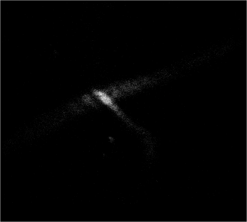 The metric value of the image after AO correction, shown in Fig. 4(d), increased nearly twofold with the same excitation power. It takes about 150 to 200 iterations to complete the correction. It also reveals that the closed-loop stability decreases, because the index-mismatch aberration increases with image depth and perturbations during SPGD iterative process may go beyond the capability of the DM to compensate. The compensation profile of the DM is shown in Fig. 4(c). The aberration corrected images obtained with the microscope show enhanced contrast and improvement of fluorescence intensity. The AO could be widely beneficial in confocal microscopes that often suffer from the detrimental effects of system- and specimen-induced aberrations, especially for in vivo imaging. 4.Discussion and ConclusionIn vivo bone marrow vasculature imaging has played an important role in research regarding the dynamic interactions between tumor/stem cells and the bone marrow microenvironment. We have demonstrated confocal fluorescence microscopy with a sensorless AO system which could be used for in vivo imaging of mouse bone marrow. The results show improved imaging depth and imaging resolution. With aberration correction, finer bone marrow cavity structure information and more accurate locations of cells could be observed. The custom built confocal fluorescence microscope could perform real-time imaging at the video level, which is ideally suited for in vivo imaging and long-term observation of vascular cells within the bone marrow. Because of the flow characteristics of blood, guide star methods are not suitable because it is not convenient to fix injected fluorescent beads or find fluorescent proteins in vessels in vivo. Therefore, a wavefront sensorless scheme was chosen in the microscopy. Compared to conventional AO using direct wavefront sensing which needs a guide star and wavefront sensor, such as the Hartmann sensor, to measure the aberration of the imaging-path from the guide star, sensorless AO has a simpler system architecture and can non-invasively correct aberrations for different depths of biological tissue, which is very important in the field of microscopy. The aberration magnitudes of bone marrow during in vivo imagine have significant variations at different imaging depths. Therefore, the AO method should be adaptive to correct different magnitudes of aberrations. An optimization algorithm based on a random search was selected because of its advantages of better convergence robustness for aberrations of various magnitudes. Compared to the modal sensor algorithm, it is simple and does not require a system calibration process.21 The modal sensor needs a different control basis for different magnitudes’ aberrations22,23 and also requires a complex system calibration process.21 Correction speed also has important significance for fluorescence imaging because of the photo bleaching issue for fluorescent dyes. Considering the range of the algorithm application and correction speed, we choose the SPGD algorithm, which has robust convergence characteristics for different aberrations and can complete the aberration correction in seconds in a confocal fluorescence microscope, which is first time this has done to the best of our knowledge. The experiment of in vivo mouse bone marrow imaging was completed. Fluorescence images of blood vessels at different depths are obtained and image contrast has been significantly improved after correction. For the blood vessel at the depth of , the convergence process was relatively stable and more blood cell morphology can clearly be observed after correction. For the blood vessel at the depth of , enhancement of the fluorescence intensity after correction was also observed, but the stability of the convergence process decreased. The main reason is that the fitting ability of the DM is limited by the drive stroke volume; therefore, some drives were saturated with deeper imaging position. In addition, the lower resolution of the image of a deeper blood vessel after correction was observed, mainly due to more severe scattering.24 The results prove that the image-based wavefront sensorless AO with the SPGD algorithm could meet the requirements of aberration correction for in vivo imaging in real-time confocal microscopy. For the optimization of the first 15 Zernike modes, typically 100 to 200 images are necessary to achieve good correction results. It takes 5 to 7 s to accomplish aberration correction, which is not conducive in the cases with more stringent time requirements. The convergence time is mainly limited by the imaging speed of the microscope and the convergence rate of the SPGD algorithm. An improved SPGD algorithm or combining it with other optimization algorithms such as the modal algorithm may be a potential solution to accelerate the process of aberration correction. This will be the next focus of our future work. To conclude, by incorporating an SPGD-based AO in a confocal fluorescence microscope, we demonstrated that the correct use of AO reduces specimen-induced aberrations in vivo in the mouse skull marrow. The fluorescence images with aberration correction show enhanced contrast and improvement of fluorescence intensity. Therefore, AO would play an important role in the application of many physiological imaging techniques in vivo. While the confocal fluorescence microscopy could perform real-time imaging of blood vessels. Not only can the 3-D structure be observed, but the migration of blood cells or other observations of immune cells in the blood vessels can also be observed. It would be the ideal tool for study of vascular dynamics in future. AcknowledgmentsThis work is supported by the National Major Scientific Equipment program (Grant No. 2012YQ120080), the National Science Foundation of China (Grant No. 61108082), the Sichuan Youth Science and Technology Foundation (Grant No. 2013JQ0028), and the West Light Foundation of the Chinese Academy of Sciences. The authors would like to thank Hao Li and Jing Lu for many helpful discussions regarding this project. ReferencesD. A. Sipkinset al.,
“In vivo imaging of specialized bone marrow endothelial microdomains for tumour engraftment,”
Nature, 435
(7044), 969
–973
(2005). http://dx.doi.org/10.1038/nature03703 NATUAS 0028-0836 Google Scholar
C. L. CelsoJ. W. WuC. P. Lin,
“In vivo imaging of hematopoietic stem cells and their microenvironment,”
J. Biophotonics, 2
(11), 619
–631
(2009). http://dx.doi.org/10.1002/jbio.v2:11 JBOIBX 1864-063X Google Scholar
P. TörökS. HewlettP. Varga,
“The role of specimen-induced spherical aberration in confocal microscopy,”
J. Microsc., 188
(2), 158
–172
(1997). http://dx.doi.org/10.1046/j.1365-2818.1997.2440802.x JMICAR 0022-2720 Google Scholar
M. SchwertnerM. BoothT. Wilson,
“Characterizing specimen induced aberrations for high NA adaptive optical microscopy,”
Opt. Express, 12
(26), 6540
–6552
(2004). http://dx.doi.org/10.1364/OPEX.12.006540 OPEXFF 1094-4087 Google Scholar
M. BoothM. NeilT. Wilson,
“Aberration correction for confocal imaging in refractive-index mismatched media,”
J. Microsc., 192
(2), 90
–98
(1998). http://dx.doi.org/10.1111/j.1365-2818.1998.99999.x JMICAR 0022-2720 Google Scholar
J. Luet al.,
“Retina imaging in vivo with the adaptive optics confocal scanning laser ophthalmoscope,”
Proc. SPIE, 7519 75191
(2009). http://dx.doi.org/10.1117/12.845751 PSISDG 0277-786X Google Scholar
B. Hermannet al.,
“Adaptive-optics ultrahigh-resolution optical coherence tomography,”
Opt. Lett., 29
(18), 2142
–2144
(2004). http://dx.doi.org/10.1364/OL.29.002142 OPLEDP 0146-9592 Google Scholar
M. J. Boothet al.,
“Adaptive aberration correction in a confocal microscope,”
Proc. Natl. Acad. Sci.U.S.A., 99
(9), 5788
–5792
(2002). http://dx.doi.org/10.1073/pnas.082544799 PNASA6 0027-8424 Google Scholar
N. JiT. R. SatoaE. Betziga,
“Characterization and adaptive optical correction of aberrations during in vivo imaging in the mouse cortex,”
Proc. Natl. Acad. Sci.U. S. A., 109
(1), 22
–27
(2012). http://dx.doi.org/10.1073/pnas.1109202108 PNASA6 0027-8424 Google Scholar
X. TaoJ. CrestS. Kotadia,
“Live imaging using adaptive optics with fluorescent protein guide-stars,”
Opt. Express, 20
(14), 15969
–15982
(2012). http://dx.doi.org/10.1364/OE.20.015969 OPEXFF 1094-4087 Google Scholar
D. Débarreet al.,
“Image-based adaptive optics for two-photon microscopy,”
Opt. Lett., 34
(16), 2495
–2497
(2009). http://dx.doi.org/10.1364/OL.34.002495 OPLEDP 0146-9592 Google Scholar
L. Shermanet al.,
“Adaptive correction of depth-induced aberrations in multiphoton scanning microscopy using a deformable mirror,”
J. Microsc., 206
(1), 65
–71
(2002). http://dx.doi.org/10.1046/j.1365-2818.2002.01004.x JMICAR 0022-2720 Google Scholar
M. J. BoothM. A. A. NeilT. Wilson,
“New modal wave-front sensor: application to adaptive confocal fluorescence microscopy and two-photon excitation fluorescence microscopy,”
J. Opt. Soc. Am. A, 19
(10), 2112
–2120
(2002). http://dx.doi.org/10.1364/JOSAA.19.002112 JOAOD6 0740-3232 Google Scholar
A. FacomprezE. BeaurepaireD. Debarre,
“Accuracy of correction in modal sensorless adaptive optics,”
Opt. Express, 20
(3), 2598
–2612
(2012). http://dx.doi.org/10.1364/OE.20.002598 OPEXFF 1094-4087 Google Scholar
W. Lubeigtet al.,
“Search-based active optic systems for aberration correction in time-independent applications,”
Appl. Opt., 49
(3), 307
–314
(2010). http://dx.doi.org/10.1364/AO.49.000307 APOPAI 0003-6935 Google Scholar
M. A. Vorontsovet al.,
“Adaptive optics based on analog parallel stochastic optimization: analysis and experimental demonstration,”
J. Opt. Soc. Am. A, 17
(8), 307
–314
(2000). http://dx.doi.org/10.1364/JOSAA.17.001440 JOAOD6 0740-3232 Google Scholar
Y. ZhouT. BifanoC. Lin,
“Adaptive optics two photon scanning laser fluorescence microscopy,”
Proc. SPIE, 7931 79310H
(2011). http://dx.doi.org/10.1117/12.875596 PSISDG 0277-786X Google Scholar
D. Malacara, Optical Shop Testing, 7th ed.Wiley-Interscience, Hoboken, NJ
(2007). Google Scholar
J. Braat,
“Polynomial expansion of severely aberrated wavefronts,”
J. Opt. Soc. Am. A, 4
(4), 643
–650
(1987). http://dx.doi.org/10.1364/JOSAA.4.000643 JOAOD6 0740-3232 Google Scholar
M. A. Vorontsovet al.,
“Image quality criteria for an adaptive imaging system based on statistical analysis of the speckle field,”
J. Opt. Soc. Am. A, 13
(7), 1456
–1466
(1996). http://dx.doi.org/10.1364/JOSAA.13.001456 JOAOD6 0740-3232 Google Scholar
A. ThayilM. J. Booth,
“Self calibration of sensorless adaptive optical microscopes,”
J. Eur. Opt. Soc., 6 11045
(2011). http://dx.doi.org/10.2971/jeos.2011.11045 1990-2573 Google Scholar
M. J. Booth,
“Wavefront sensorless adaptive optics for large aberrations,”
Opt. Lett., 32
(1), 5
–7
(2007). http://dx.doi.org/10.1364/OL.32.000005 OPLEDP 0146-9592 Google Scholar
M. J. Booth,
“Wave front sensor-less adaptive optics: a model-based approach using sphere packings,”
Opt. Express, 14
(4), 1339
–1352
(2006). http://dx.doi.org/10.1364/OE.14.001339 OPEXFF 1094-4087 Google Scholar
E. Chaigneauet al.,
“Impact of wavefront distortion and scattering on 2-photon microscopy in mammalian brain tissue,”
Opt. Express, 19
(23), 22755
–22774
(2011). http://dx.doi.org/10.1364/OE.19.022755 OPEXFF 1094-4087 Google Scholar
BiographyZhibin Wang is a PhD candidate at the Key Laboratory on Adaptive Optics, Institute of Optics and Electronics, Chinese Academy of Sciences. He received his BS degree in automation from the University of Science and Technology of China in 2010. His current research interests include biomedical imaging, adaptive optics, and optoelectronic systems. |


