|
|
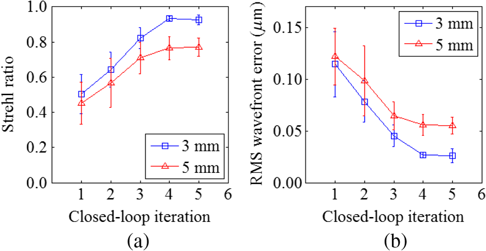
1.IntroductionThe possibility of producing and compensating Zernike aberration modes has been demonstrated earlier with the help of a liquid crystal spatial light modulator (SLM) containing 69 hexagonal pixels.1 The device, mainly limited by its response time, was tested for its ability as a wavefront corrector in a closed-loop adaptive optics (AO) system.2,3 It was identified that the low spatial resolution of the device makes it incapable of correcting ocular aberrations,4 while even lower resolution deformable mirrors (DMs) perform better.5 As anticipated, the advent of higher resolution SLMs led to better results and hence was applied to retinal imaging applications as well.4,6–8 However, these methods used additional instruments or alternate computational techniques for obtaining the information regarding the aberrations. It was shown that the SLM can also be used as a wavefront sensing device by addressing diffractive optical lenses emulating a Hartmann–Shack (HS) wavefront sensor (WFS).9 By combining the wavefront sensing and correction capabilities, the use of a single SLM for open and closed-loop AO has been demonstrated earlier.10,11 In addition to being cost effective, the AO system based on a single SLM helps in tuning the WFS parameters of the digital HS. The SLM can also be used as a pyramid wavefront sensor (PWS),12,13 a signal-based WFS,14 or a phase-shifting point diffraction interferometer (PS-PDI).15 The location of the SLM at the focal plane in PWS and PS-PDI configurations12,15 does not permit high-resolution wavefront correction with the same SLM in a single-pass arrangement. The optical design of a signal-based WFS allows closed-loop operation. However, it is limited by the slow response time of the SLM, and consequently, even more time is required for mode-wise wavefront correction.14 Although the SLM has been employed for aberration compensation in open-loop retinal imaging with a separate WFS, it has not been used for both sensing and correction of aberrations in ophthalmic applications. This is due to the limitations of the SLM’s slow response and limited phase modulation depth. Under these circumstances, it becomes crucial to reduce the sensing time and adopt efficient wavefront reconstruction methods. In this paper, we present an improved aberration correction capability and reduced time. This is achieved by increased sampling and utilizing the active area of the SLM to its full capacity. An earlier closed-loop AO system with a single SLM employed 35 subapertures alone due to beam diameter constraints.11 Here, sampling was nearly increased by a factor of 4 by employing beam resizing optics and generating 137 active subapertures. Although the use of a greater number of subapertures decreases the speed of the closed-loop system, it helps in significantly improving the accuracy of wavefront sensing, and hence improves convergence. Wavefront sensing with the HS involves two important steps. First, the local “” and “” slopes of the wavefront are determined by estimating the location of the HS spots using centroiding algorithms. Second, the wavefront shape is calculated from the local slope values using the method of least squares. The performance of four different centroiding methods was studied while estimating the location of the HS spots including center of gravity, weighted center of gravity, intensity weighted centroiding (IWC),16 and matched filter.17,18 The working of the closed-loop AO system was initially tested by sensing and correcting Zernike aberrations introduced by a DM. Next, the closed-loop AO system was demonstrated on an artificial eye. The correction capability of different Zernike modes and the number of closed-loop iterations required to achieve diffraction-limited resolution was determined. Finally, the closed-loop AO system was tested by correcting the aberrations in backscattered light from the eyes of three healthy human subjects (authors). The following section describes the experimental setup of the closed-loop AO system based on a single SLM and the method of wavefront sensing. 2.Method2.1.Experimental SetupThe phase of the incoming plane wavefront of a collimated 632.8 nm He-Ne laser beam was manipulated with the help of a 140-actuator MEMS DM from Boston Micromachines™ (Watertown, Massachusetts). The SLM (Holoeye: LC2012, and pixel ) placed in the conjugate plane of the DM was used for wavefront sensing and aberration compensation. The schematic diagram of the optical layout is shown in Fig. 1. To utilize the larger active area of the SLM, the beam size was increased by a factor of 4 using beam resizing optics. The beam exiting the SLM was divided into two parts using a beam splitter. The transmission beam was used to conjugate the plane of the DM with a commercial HS WFS. In comparison with the commercial HS, which had 311 active subapertures, the SLM generated 137 subapertures alone. The beam reflecting off the beam splitter was directed onto a CCD camera, which was placed in the conjugate plane of the focal spots generated by addressing digital diffractive optical lenses on the SLM. It has to be noted that the CCD camera is not in the conjugate plane of the SLM or the DM. Fig. 1Schematic diagram of the optical layout for implementing a closed-loop adaptive optics system with the spatial light modulator (SLM). CS is the collimated light source, and and are the beam splitters. are the achromatic lenses, and are the mirrors. FP is the focal plane of the diffractive optical lenses. PP represents the pupil plane, and CP is the conjugate plane. 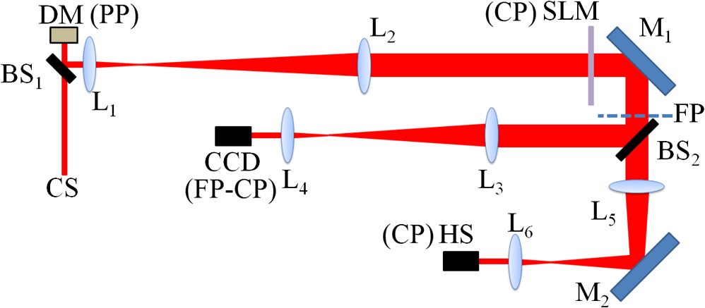 The DM was operated in a closed-loop mode and the residual root-mean-square (RMS) wavefront error is about after calibration. First, different low-order Zernike aberrations were introduced with the help of the DM. Then, the SLM-based closed-loop wavefront sensing and correction system was switched on. The wavefronts sensed after individual closed-loop wavefront correction were decomposed into Zernike modes. Second, the performance of the system was tested using an artificial eye, which consists of an achromatic lens (focal length: 25 mm) and a rotating white sheet of paper emulating an artificial retina. The rotation allows minimizing deteriorations caused by speckles. The performance of the closed-loop AO system was evaluated based on the estimated Strehl ratio after individual closed-loop iteration and the RMS wavefront error (Appendix A). 2.2.Wavefront SensingMainly two different centroiding methods, IWC and matched filter centroiding (MFC), were implemented.18 To overcome the effects of noise under conditions of low signal-to-noise ratio, the weighting could be further increased to the fourth power of intensity and hence modified IWC to IWC4 (Appendix B). MFC was implemented by calculating the convolution of the subaperture intensity function with a reference Gaussian function. Applying parabolic interpolation on the resultant convolution matrix, the centroid was estimated.18 The corresponding “” and “” slope values are calculated from the ratio of the displacement of the digital HS spots from a reference location and the focal length of the diffractive optical lenses. Wavefront reconstruction from the estimated slope values was performed by using the singular value decomposition technique and the slope geometry of Southwell.19 3.ResultsThe DM calibrated along with a commercial HS WFS was used to introduce defocus, astigmatism, coma, spherical, and secondary astigmatism aberrations. The wavefront sensing of the introduced Zernike aberrations with the SLM (after one closed-loop iteration) showed good agreement with the measurements of the commercial HS as illustrated in Fig. 2. In addition, Fig. 3 shows a comparison of the corresponding measured Zernike coefficients while detecting Zernike aberrations induced by the DM. It was observed that in comparison with IWC4 and MFC, the IWC method underestimated the wavefront error after a single closed-loop iteration. The superior performance of IWC4 in comparison with IWC is because of the improved noise cancellation. Fig. 2Comparison of wavefront reconstructions obtained with the digital Hartmann–Shack (HS) and the commercial HS while sensing five different Zernike aberrations after a single closed-loop operation. The peak-to-valley of the introduced Zernike aberrations as measured by the commercial HS is 1.74, 1.78, 2.06, 1.89, and for defocus, astigmatism, coma, spherical, and secondary astigmatism, respectively. The difference between the HS estimated wavefront and the digital HS measured wavefront (after one closed-loop iteration) for MFC, IWC, and IWC4 methods is also shown here.  Fig. 3Comparison of the corresponding measured Zernike coefficients while sensing Zernike aberrations induced by the deformable mirror (DM). 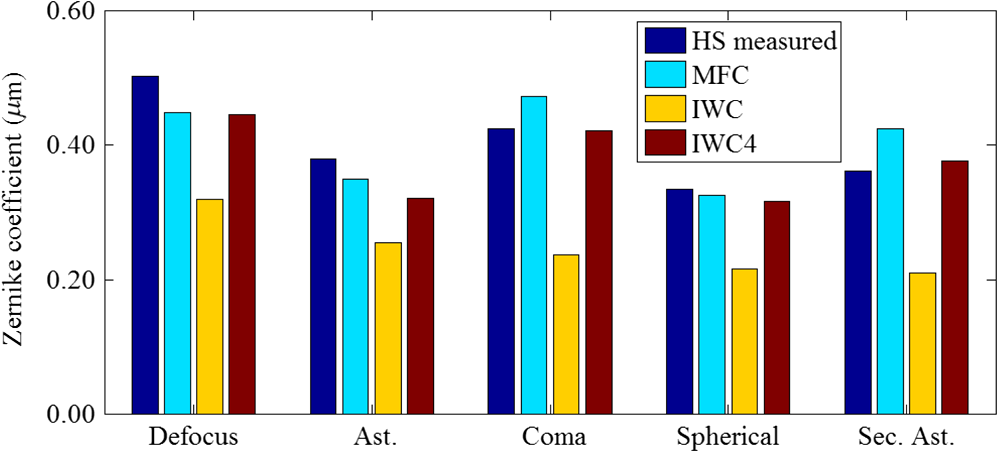 The plots of the estimated Strehl ratio and RMS wavefront error as a function of closed-loop iterations are shown in Fig. 4. The RMS wavefront error is obtained from the residual wavefront error estimated by the SLM-based digital HS after each iteration. It can be seen that in the case of defocus and astigmatism aberrations, five closed-loop operations are enough to achieve a Strehl ratio beyond 0.8. However, coma, spherical, and secondary astigmatism needed a few more iterations to achieve similar performance. The high value of the RMS wavefront error after the first iteration connotes an underestimation of the wavefront error. This underestimation is attributed to the underestimated local slope values and hence centroid estimate. In addition, SLM diffraction losses also contribute to this underestimation, which necessitates a closed-loop operation for reliable wavefront correction with the SLM alone. Fig. 4Propagation of Strehl ratio and root-mean-square (RMS) wavefront error with increasing closed-loop iterations while correcting Zernike aberrations—defocus, astigmatism, coma, spherical, and secondary astigmatism induced by a DM. The peak-to-valley of the introduced Zernike aberrations as measured by the commercial HS is 1.74, 1.78, 2.06, 1.89, and for defocus, astigmatism, coma, spherical, and secondary astigmatism, respectively. The error bars represent the standard deviation of five different measurements under identical conditions. 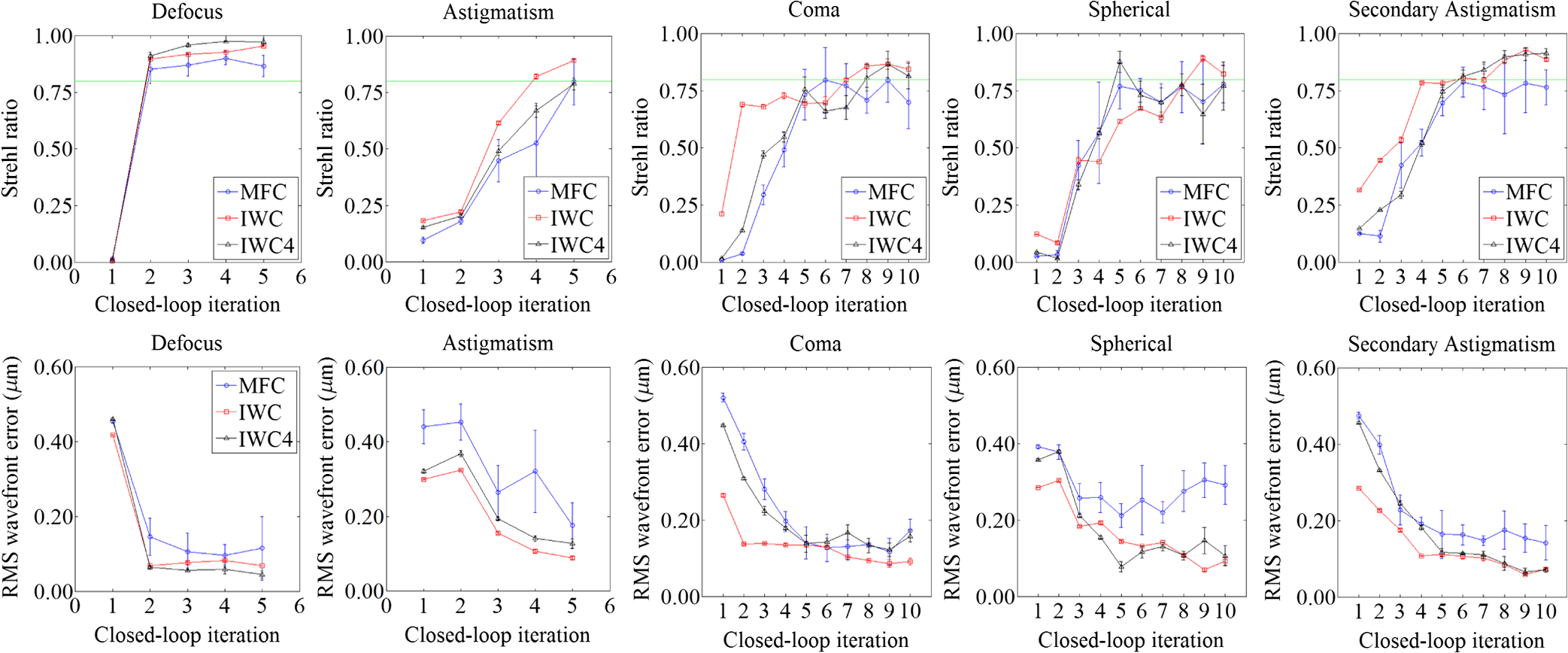 Simple center of gravity and weighted center of gravity methods were also implemented. However, because of significant underestimation of the wavefront error, closed-loop convergence could not be achieved even after 20 closed-loop iterations. It was observed that IWC4 and MFC algorithms showed superior performance out of the tested centroid detection methods while sensing different Zernike aberrations. However, it has to be noted that the IWC and IWC4 algorithms are much faster than the MFC, nearly a factor of 5 in our case. Figure 5 shows a portion of the background subtracted digital HS spots recorded by the CCD camera. For better visualization of the spots, the contrast of the spots has been enhanced by squaring the intensity values. It can be observed that the background subtracted HS spots are less circular in shape making it less relevant to use a Gaussian reference function in the MFC technique. Fig. 5A portion of the 137 digital HS spots recorded by the CCD camera: (a) artificial eye and (b) healthy human subject (BV). 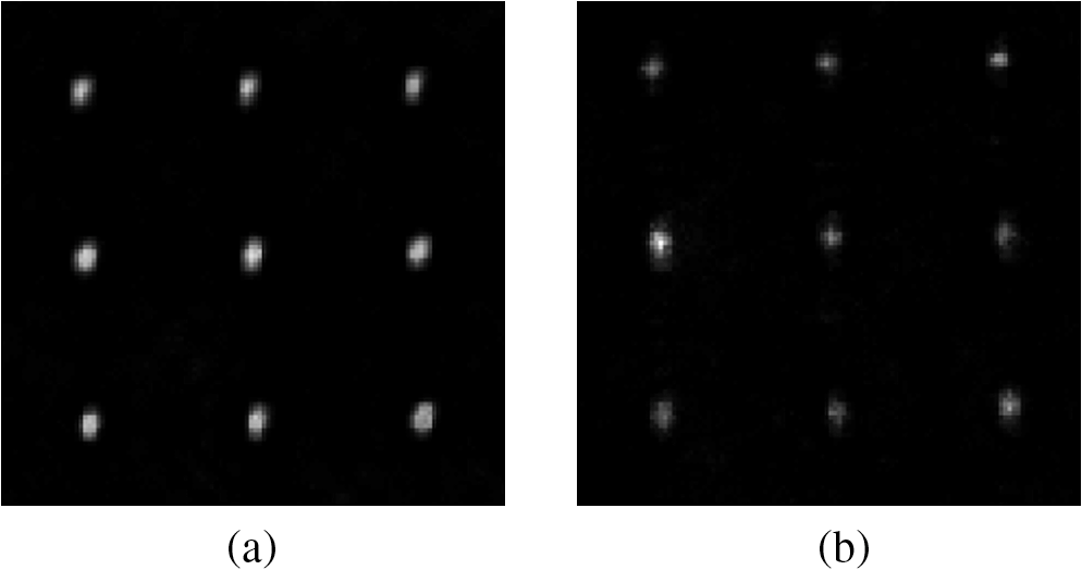 Another way to evaluate the performance of the AO system is by measuring the aberrated PSF after each closed-loop iteration. The optical configuration shown in Fig. 1 allows measurements with a commercial HS WFS while correcting the Zernike aberrations induced by the DM. The PSF estimated from these measurements confirmed the closed-loop performance of the AO system. It has to be noted that the comparison between the HS and the SLM-based WFS suffer noncommon path errors and hence tilt aberration terms were excluded in the HS estimated PSF. In the case of the artificial eye, it is observed that the induced aberrations are dominated by primary defocus. Along with diffraction losses and centroiding errors, the instability of the spots caused by the nonplanarity of the artificially generated retinal plane adds to further errors. For this reason, in comparison with primary defocus, the closed-loop AO for the artificial eye required a greater number of iterations for convergence as shown in Fig. 6. The print-through effects of the DM were partly eliminated by the background subtraction. While correcting the aberrations generated by the simulated artificial eye, the estimated Strehl ratio increased from 0.1 to beyond 0.8 when the IWC4 method was used. Fig. 6Propagation of Strehl ratio and RMS wavefront error with increasing closed-loop iterations while correcting aberrations from an artificial eye. The error bars represent the standard deviation of 10 different measurements under identical conditions.  Temporal bandwidth is a crucial component in a closed-loop AO system and the SLM’s response time plays a key role. For the SLM used here, the display frequency is 60 Hz. Further delays are introduced by the image acquisition rate and the total computing time. It is known that an AO system operating at a bandwidth beyond 10 Hz would be able to trace all the meaningful fluctuations in the eye’s aberrations. However, under a purely corneal approximation, a closed-loop bandwidth of 1 to 2 Hz could still achieve diffraction-limited imaging over a dilated pupil.20 The estimated closed-loop AO bandwidth is 1 and 0.2 Hz while using IWC/IWC4 and MFC methods, respectively. The speed of this closed-loop AO system can be improved by using efficient algorithms, faster processors and SLMs with quicker response time. In the case of IWC and IWC4, image acquisition consumed 60% of the total time. Centroid detection took nearly 4% and the estimation of the wavefront from the local slope values utilized 4% of the total time. The rest of the time is spent on wavefront correction, which includes delays from the SLM response. Strehl ratio and RMS wavefront error were estimated by carrying out closed-loop AO measurements while correcting aberrations from the eyes of the authors (Fig. 7), which replaced the DM (Fig. 1). (see Fig. 1) was replaced with a plane mirror for efficient use of the backscattered light from the eyes. For better speed and accuracy, IWC4 was used in the measurements with the eye. The diameter of the collimated beam incident on the eye was limited to 1 mm, and the beam power was adjusted in the range 0.5 to using neutral density filters for different eyes of the subjects by taking into account the intensity of the backscattered light. In order to minimize unwanted head and eye motion, a bite bar was used. Here, the reference spots were obtained by placing a plane mirror at the location of the eye. Author Akondi observed a greater amount of scattering in the left than in the right eye. This can be attributed to corneal scattering and greater magnitude of the measured defocus coefficient in the left eye as compared with the right. The results by AR were significantly affected by corneal scattering and tear film. Fig. 7Propagation of Strehl ratio and RMS wavefront error with increasing closed-loop iterations while correcting aberrations from the authors’ eyes. IWC4 method was used for estimating the spot centroids. The measurements were made over a pupil size of 3 mm. The error bars represent the standard error from five different measurements under identical conditions. 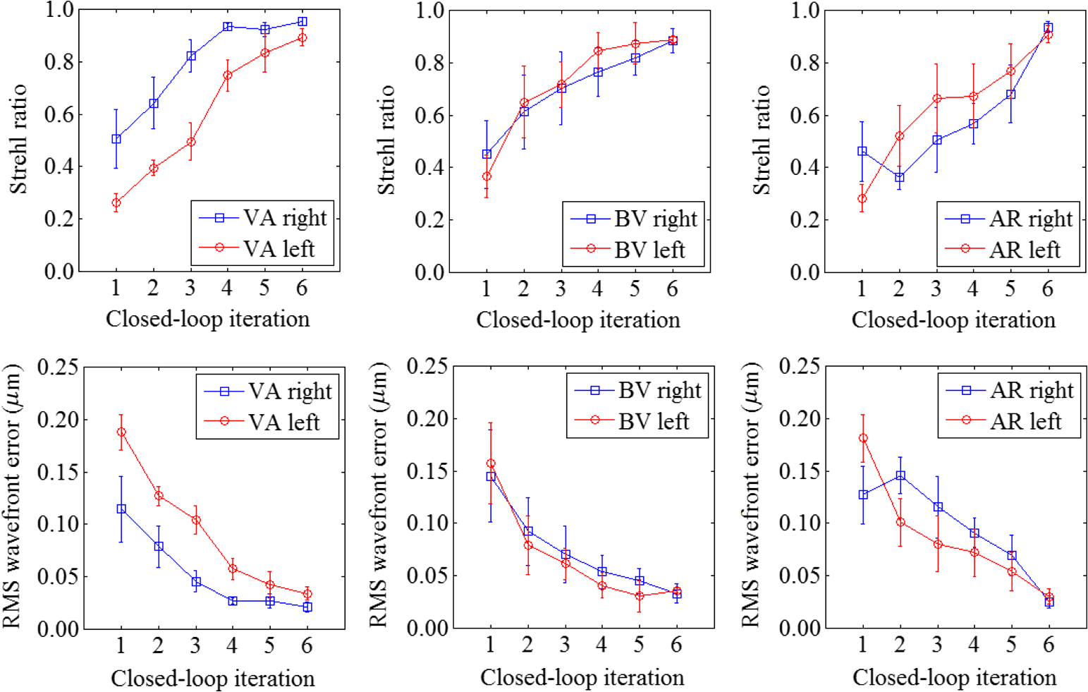 It was observed that by increasing the power of the beam incident on the right eye of VA from 1.0 to , diffraction-limited resolution can be achieved with three closed-loop iterations instead of four; this indicates an improved rate of closed-loop convergence with increased signal-to-noise ratio. With an increased pupil diameter, the performance of the proposed AO system dropped as shown in Fig. 8 for the case of IWC4 for subject VA. As the pupil size increases, the magnitude of the aberrations increase and consequently, a greater number of closed-loop iterations will be necessary to achieve better wavefront correction. Hence, extending the technique to larger, dilated pupils will not fundamentally affect the approach. 4.DiscussionFigures 4 and 6 clearly indicate that IWC4 holds a slight advantage over IWC and MFC because of its noise insensitivity and greater capability in determining the location of the intensity peak. By controlling the source intensity, the performance of IWC, IWC4, and MFC methods was compared while correcting different Zernike aberrations introduced by the DM. It was observed in the case of IWC4 that the wavefront correction after 10 closed-loop iterations, starting from a minimum intensity level and gradually increasing the intensity by a factor of 2 in six steps, did not have an effect on the final Strehl ratio and RMS wavefront error. This shows the supremacy of IWC4 over a range of intensity levels. Strehl ratio was estimated while correcting DM-induced spherical aberrations of different magnitudes. It was noted that the closed-loop convergence is quicker when the magnitude of the induced aberration is smaller. While using IWC4 and correcting a DM-induced spherical aberration of peak-to-valley, nine closed-loop iterations were required to achieve a Strehl ratio more than 0.8, whereas spherical aberration with a peak-to-valley of needed six iterations. When the DM was used for the generation of Zernike aberrations, reference spots were obtained with the DM generating a plane wavefront. The subtraction of background, which led to irregular shapes of the digital HS spots, does not allow choosing an appropriate reference in the case when aberrations were introduced with the DM. By varying the reference spot size, a search for the optimal spot size was made. The Strehl ratio estimated at the end of 10 closed-loop iterations was used as an evaluation metric. It was found that varying the size of the reference Gaussian spot about the actual spot size did not show a significant effect on the performance of the closed-loop AO system. The use of zonal wavefront reconstruction helped in retaining the high-resolution wavefront sensing capability of the 137-subaperture digital HS based on the SLM. In addition, a modal wavefront correction approach allowed qualitative and quantitative determination of the Zernike modes. Increasing the number of Zernike modes from four orders to five did not improve the performance of the closed-loop AO system any further, suggesting that the induced aberrations contained predominantly four orders of Zernike. The monochromatic nature of the SLM, its pixelation, polarization dependence, low speeds, and errors due to -phase wrapping are a few disadvantages of the demonstrated closed-loop AO system. In addition, the optical design does not allow placing the DM in the conjugate plane of the camera because the camera is in the focal plane of the diffractive optical lenses. This leads to prominent print-through features in the focal spot images. Background subtraction significantly removed these adverse effects. In the case of the artificial eye, the rotation of the white sheet helped in eliminating the speckle pattern that was present in the static case. It should be noted that this may not be the case while examining the human eye, which could cause subject-dependent scattering noise. A time delay of 0.1 s was deliberately introduced after addressing the SLM with the correction pattern in every closed-loop. This is to prevent triggering camera acquisition before the SLM responds to the addressed wavefront. This further decreased the closed-loop AO bandwidth. An occasional increase in the estimated RMS wavefront error with increasing closed-loop iteration does not necessarily imply a decrease in Strehl ratio as also observed in the case of MFC for spherical and astigmatism aberrations (see Fig. 4). The increase in the RMS wavefront error is attributed to the observed incorrect wavefront compensation near the boundary, which has a less significant effect on the Strehl ratio. Here, MFC was not tested with human eyes since it utilizes greater computational time (six closed-loop iterations need 30 s) that makes fixation difficult. Future studies will involve high-resolution SLMs with quicker response and smaller pixel pitch. The use of a longer wavelength IR radiation will improve aberration measurement because of its lower scattering. The contamination of spots in a closed-loop that may occur from wavefront correction in the region of the SLM overlapping with the diffractive optical lenses can be avoided by using two separate portions of the same SLM for wavefront sensing and aberration compensation.11 Taking the advantage of the control on the HS parameters that the SLM device allows, experiments will be conducted to optimize the performance of the SLM-based closed-loop AO system. Further, by introducing smarter control algorithms and accelerating the centroid detection step, a high-bandwidth closed-loop AO system will be developed for retinal imaging applications. In conclusion, the possibility of sensing and correcting human eye optical aberrations using a single SLM is demonstrated by testing the developed closed-loop AO system by correcting aberrations from a DM, an artificially simulated eye and three healthy subjects. The SLM-based closed-loop AO system showed good promise in correcting the optical aberrations introduced. Hence, this system could be applied to a range of applications including retinal imaging and microscopy. AppendicesAppendix A:RMS Wavefront ErrorThe estimated RMS wavefront error is calculated as follows: where is the Zernike coefficient with index “” for the wavefront sensed in the ’th closed-loop iteration. Piston () and tilt (, 2) aberration terms that do not have an effect on the shape of the point spread function were excluded.Appendix B:Centroid Detection MethodsIn the IWC method, the centroid location, for a given subaperture is estimated from the intensity distribution in the subaperture spot using where and represent the “” and “” coordinates for a given subaperture plane and is the intensity (normalized) distribution. To overcome the effects of noise under conditions of low signal-to-noise ratio, the weighting could be further increased to fourth power of intensity and hence modified IWC to IWC4 as follows:AcknowledgmentsThis research has been realized with financial support from Science Foundation Ireland (Grant 08/IN.1/B2053) and UCD seed funding. ReferencesG. D. Love,
“Wave-front correction and production of Zernike modes with a liquid-crystal spatial light modulator,”
Appl. Opt., 36
(7), 1517
–1520
(1997). http://dx.doi.org/10.1364/AO.36.001517 APOPAI 0003-6935 Google Scholar
J. Gourlayet al.,
“A real-time closed-loop liquid crystal adaptive optics system: first results,”
Opt. Commun., 137
(1–3), 17
–21
(1997). http://dx.doi.org/10.1016/S0030-4018(96)00756-0 OPCOB8 0030-4018 Google Scholar
P. M. Birchet al.,
“Real-time optical aberration correction with a ferroelectric liquid-crystal spatial light modulator,”
Appl. Opt., 37
(11), 2164
–2169
(1998). http://dx.doi.org/10.1364/AO.37.002164 APOPAI 0003-6935 Google Scholar
F. Vargas-MartinP. M. PrietoP. Artal,
“Correction of the aberrations in the human eye with a liquid-crystal spatial light modulator: limits to performance,”
J. Opt. Soc. Am. A, 15
(9), 2552
–2562
(1998). http://dx.doi.org/10.1364/JOSAA.15.002552 JOAOD6 0740-3232 Google Scholar
E. J. FernandezI. IglesiasP. Artal,
“Closed-loop adaptive optics in the human eye,”
Opt. Lett., 26
(10), 746
–748
(2001). http://dx.doi.org/10.1364/OL.26.000746 OPLEDP 0146-9592 Google Scholar
L. Huet al.,
“Phase-only liquid crystal spatial light modulator for wavefront correction with high precision,”
Opt. Express, 12
(26), 6403
–6409
(2004). http://dx.doi.org/10.1364/OPEX.12.006403 OPEXFF 1094-4087 Google Scholar
N. Konget al.,
“Optimization of the open-loop liquid crystal adaptive optics retinal imaging system,”
J. Biomed. Opt., 17
(2), 026001
(2012). http://dx.doi.org/10.1117/1.JBO.17.2.026001 JBOPFO 1083-3668 Google Scholar
C. Liet al.,
“High-resolution retinal imaging through open-loop adaptive optics,”
J. Biomed. Opt., 15
(4), 046009
(2010). http://dx.doi.org/10.1117/1.3466581 JBOPFO 1083-3668 Google Scholar
L. Zhaoet al.,
“Efficient implementation of a spatial light modulator as a diffractive optical microlens array in a digital Shack–Hartmann wavefront sensor,”
Appl. Opt., 45
(1), 90
–94
(2006). http://dx.doi.org/10.1364/AO.45.000090 APOPAI 0003-6935 Google Scholar
J. Arineset al.,
“Measurement and compensation of optical aberrations using a single spatial light modulator,”
Opt. Express, 15
(23), 15287
–15292
(2007). http://dx.doi.org/10.1364/OE.15.015287 OPEXFF 1094-4087 Google Scholar
R. Martinez-Cuenaet al.,
“Closed-loop adaptive optics with a single element for wavefront sensing and correction,”
Opt. Lett., 36
(18), 3702
–3704
(2011). http://dx.doi.org/10.1364/OL.36.003702 OPLEDP 0146-9592 Google Scholar
V. AkondiS. CastilloB. Vohnsen,
“Digital pyramid wavefront sensor with tunable modulation,”
Opt. Express, 21
(15), 18261
–18272
(2013). http://dx.doi.org/10.1364/OE.21.018261 OPEXFF 1094-4087 Google Scholar
V. AkondiS. CastilloB. Vohnsen,
“Multi-faceted digital pyramid wavefront sensor,”
Opt. Commun., 323 77
–86
(2014). http://dx.doi.org/10.1016/j.optcom.2014.03.004 OPCOB8 0030-4018 Google Scholar
A. R. JewelV. AkondiB. Vohnsen,
“A direct comparison between a MEMS deformable mirror and a liquid crystal spatial light modulator in signal-based wavefront sensing,”
J. Eur. Opt. Soc. Rapid Publ., 8 13073-1
–13073-10
(2013). http://dx.doi.org/10.2971/jeos.2013.13073 1990-2573 Google Scholar
V. AkondiA. R. JewelB. Vohnsen,
“Digital phase-shifting point diffraction interferometer,”
Opt. Lett., 39
(6), 1641
–1644
(2014). http://dx.doi.org/10.1364/OL.39.001641 OPLEDP 0146-9592 Google Scholar
V. AkondiM. B. RoopashreeB. R. Prasad,
“Advanced methods for improving the efficiency of a Shack–Hartmann wavefront sensor,”
Topics in Adaptive Optics, 167
–196 InTech, Rijeka, Croatia
(2012). Google Scholar
C. LerouxC. Dainty,
“Estimation of centroid positions with a matched-filter algorithm: relevance for aberrometry of the eye,”
Opt. Express, 18
(2), 1197
–1206
(2010). http://dx.doi.org/10.1364/OE.18.001197 OPEXFF 1094-4087 Google Scholar
V. AkondiB. Vohnsen,
“Myopic aberrations: impact of centroiding noise in Hartmann–Shack wavefront sensing,”
Ophthal. Physiol. Opt., 33
(4), 434
–443
(2013). http://dx.doi.org/10.1111/opo.12076 OPOPD5 0275-5408 Google Scholar
W. H. Southwell,
“Wave-front estimation from wave-front slope measurements,”
J. Opt. Soc. Am., 70
(8), 998
–1006
(1980). http://dx.doi.org/10.1364/JOSA.70.000998 JOSAAH 0030-3941 Google Scholar
H. Hoferet al.,
“Dynamics of the eye’s wave aberration,”
J. Opt. Soc. Am. A, 18
(3), 497
–506
(2001). http://dx.doi.org/10.1364/JOSAA.18.000497 JOAOD6 0740-3232 Google Scholar
BiographyVyas Akondi is a postdoctoral research fellow at the School of Physics, University College Dublin. He received his PhD degree from the Indian Institute of Science, Bangalore, in 2012. He authored 16 journal articles. His research interests include wavefront sensing, adaptive optics, vision science, microscopy, and astronomical instrumentation. A recipient of several travel grants and best paper awards, he serves as a member of the Optical Metrology Technical Group under the Optical Society of America. Md. Atikur Rahman Jewel is currently a PhD student of the Advanced Optical Imaging Group, School of Physics, University College Dublin, Ireland. Development and application of adaptive optics to microscopy are his current research interests. He has developed a signal-based wavefront sensor for the microscopic imaging system. He did his MSc in optics and biophysics at the University of Twente, Enschede, Netherlands. His future research interests are adaptive optics, second harmonic microscopy, and ophthalmology. Brian Vohnsen is a senior lecturer in the School of Physics, University College Dublin, where he founded the Advanced Optical Imaging Group in 2008. His research interests are centered on biomedical optics and spans from novel microscopy and adaptive optics to the biophotonic properties of the human eye. He chairs the Applications of Visual Science Steering Group below the Optical Society of America and is current subcommittee chair for FiO Vision and Color. |