
|
|
|
Fluorescence microscopy is routinely used in many fields including biophysics, biochemistry, and biomedicine. In addition to the fluorescence intensity, other fluorescence parameters such as excitation and emission spectra, polarization, and lifetime can be used to better characterize the sample.1–4 The particular advantage of fluorescence lifetime imaging (FLIM) is that the lifetime measurement does not depend on fluorophore concentration; therefore, it can reveal information about the microenvironment of the fluorophore, which is the reason that FLIM has drawn a lot of attention.2,4–11 FLIM in its simplest form can be used as a contrast enhancing technique to differentiate various fluorescent species or to sense the local fluorophore environment as interactions with other molecules. Until now, the vast majority of FLIM applications have been focused in biomedicine and life science research fields, as the technique is nondestructive or minimally invasive and is suitable for monitoring living cells and tissues.7–9 Fluorescence resonance energy transfer is often detected with FLIM to identify protein-protein interactions or conformational changes of proteins.10 Moreover, there are many applications in diverse fields, such as forensic science, combustion research, luminescence mapping in diamond, microfluidic system, art conservation, and lipid order problems in physical chemistry.7 Efforts are underway to use FLIM combined with a phasor plot approach for clinical diagnostics.11 In the last decades, two-photon excited FLIM has become a powerful tool in biology and biomedical studies. Most of the current FLIM imaging systems employ galvo-mirrors to scan the laser spot across the biological samples, due to their advantages of large scanning angles and no dispersion effect. However, there are several disadvantages. The moving speed of galvo-mirrors is relatively slow and they could not provide flexibility for scanning rate selection. Another disadvantage is that the mechanical scanners cannot rapidly access a specific point in the sample, leading to limited imaging speed and flexibility.12,13 Therefore, this method does not allow for fast functional event detection in live biological samples. To increase the imaging speed, other scanning methods have been proposed in recent years. Lechleiter et al. reported the multiphoton adaptation of a confocal microscope that uses an acoustic optical deflector (AOD) for beam steering.14 Roorda et al. proposed a video-rate two-photon imaging system based on AOD.15 Kirkby et al. developed a high speed three-dimensional (3-D) AOD for femtosecond two-photon imaging.16 Among them, scanning using acousto-optic deflectors has been considered as the most promising method.17–19 The advantage of using AOD as scanners is that they have no mechanical moving parts, which allows for rapidly steering the laser beam to any point in the field of view (FOV) with high precision and repeatability. However, AOD has some drawbacks. For example, the dispersion of ultrafast laser light limits its application in multiphoton microscopy. In order to make full use of the advantages of AODs as flexible scanning devices with random-addressing capability, Lv et al.17 proposed a simple dispersion compensation mechanism using a single prism in a two-photon excitation fluorescence microscope. In 2008, Iyer et al.18 reported a new imaging system that utilizes a unique arrangement of AOD to steer a focused, ultrafast laser beam to arbitrary locations in 3-D space without moving the objective lens. In 2013, we presented a flexible FLIM microscopy system based on two-dimensional (2-D) AOD to achieve fast beam scanning across the sample.2 The AOD-FLIM system can provide random access to the regions of interest (ROI). However, the single photon counting modules (SPCM, which is the FLIM control software, Becker & Hickl) system of the AOD-FLIM system worked under the “single imaging” mode; therefore, the imaging area is limited and the image reconstruction is based on the lifetime measurement of each pixel, making the experimental process complicated and time-consuming. Due to these limitations, the AOD-FLIM system is not suitable for in vivo imaging. In this paper, we report the implementation of dynamic fluorescence lifetime imaging (D-FLIM) using a pair of AOD and a time-correlated single-photon counting (TCSPC) lifetime imaging module for the random ROI study in the sample as well as an SPCM system that operates in “FIFO imaging” mode. The AOD devices are used to rapidly scan the femtosecond laser beam across the sample, providing specific random access to the ROI. In our experiment, we used the fluorescent dye Rhodamine-6G to label live HepG2 cells, then we used tumour necrosis factor- () to induce apoptosis in HepG2 cells, and continuously recorded the fluorescence lifetime change of Rhodamine-6G in the HepG2 cells. It has been demonstrated that our system can dynamically monitor the changing process of the ROI in live biological samples. Moreover, the fluorescent dye Rhodamine-6G is a potential probe for observing the apoptosis process of live cells. Figure 1 is the schematic diagram of the D-FLIM system that is composed of a femtosecond laser, a prism, 2-D AOD scanner, a PIN, a PMT, a TCSPC module, a computer, and a microscope. The femtosecond laser is a mode-locked femtosecond laser (Spectral-Physics, Mai Tai DeepSee) with its tunable output light wavelength from 690 to 1000 nm (here we use 820 nm). The repetition rate of the laser is 80 MHz and the output power is 3.0 W. The prism is a SF10 glass prism and the apex angle is 60 deg. It is used to simultaneously compensate for the temporal and spatial dispersions. The 2-D AOD scanner (AA Optoelectronic, DTSXY-400-810, A-A) is used for an ultrafast and selected area scan, the center frequency of the 2-D AODs was 75 MHz, and the range of the scan frequency was 60 to 90 MHz. After passing the 2-D AODs, the laser is split into multiple beams, where the (0, 0) beam is used to produce the synchronization signal by PIN (PHD-400, Becker & Hickl), and the (1, 1) beam is expanded with a pair of lenses (one is a scanning lens and another is a tube lens ) before entering the objective lens. The objective lens is an Olympus UPLO 1.40 oil immersion lens. The fluorescence generated from the sample is collected by the objective lens and detected by a PMT (H7422-40, Hamamatsu), and the output of PMT is sent to the TCSPC module (SPC-150, Becker & Hickl) for measuring the fluorescence lifetime with photon counting. Fig. 1Schematic diagram of the dynamical fluorescence lifetime imaging system. Laser: Spectra-Physics, Mai Tai DeepSee, the wavelength of the output light is 820 nm; PBS: polarization beam splitter; AOD: acousto-optic deflector; DM: dichroic mirror; PMT: Hamamatsu H7422-40; Objective: Olympus UPLO 1.40 oil immersion objective.  In order to make full use of the dispersion compensation of the prism, the prism along with the two mirrors is mounted in a small optical adjustment bracket and tilted at a constant angle of 45 deg with respect to the -axis, and the incident angle of light at the prism is about 47 deg. The distance from the prism to the AODs (the AODs are fixed on a 3-D adjustment platform.) is about 35 cm to provide optimal spatial dispersion compensation. Because the compensation is sensitive to the angle of incidence at the prism, the prism and the related optics are carefully locked. The control system for AODs scanning is written in Labview (National Instruments). The signals for the system control and synchronization were provided by a multifunction DAQ card (USB-6353, National Instruments). To demonstrate the performance of the D-FLIM system, we performed FLIM experiment using a fluorescein cover slip. Figure 2 shows the experimental result. Figures 2(a) and 2(b) show the fluorescence intensity and lifetime images of a letter “F” that was selected using the mouse. The mouse selecting process generated the coordinates of the pixels on the letter “F.” Then the control system of AODs deflected the laser beam on the sample with different frequencies corresponding to the different positions on the letter “F.” Figure 2(a) is the image of fluorescence intensity with a CCD camera (CoolSNAP EZ, Photometric). Figure 2(b) is the lifetime image of Fig. 2(a). Figures 2(c) and 2(d) are the lifetime histogram and fluorescence decay curve, respectively. Figure 2(c) shows the lifetime distribution of all the pixels, providing the average lifetime of the letter “F,” which is 2.245 ns. Here, we must emphasize that the D-FLIM system is a single beam scanning method. Although multibeam scanning approaches also exist, they could not be applied to D-FLIM for random ROI. Fig. 2The images of random areas (letter F). Fluorescence intensity (a) and lifetime (b) image of letter F. (c) Lifetime histogram of image (b). (d) Fluorescence decay curve.  In order to demonstrate the capability of D-FLIM for random ROI, we used a Convallaria rhizome slide. Figure 3(a) is the fluorescence intensity image of the Convallaria rhizome slide. Figure 3(b) is the fluorescence intensity image of the ROI [the blue square in (a)], and Fig. 3(c) is the FLIM of this area. The collection time for Fig. 3(c) is 1 s. Figure 3(d) is the fluorescence decay curve of a selected point in the lifetime image. Figure 3(a) indicates that the FOV is about , and the selected area is about . The decay curve in Fig. 3(d) was analyzed using double exponential fitting. Fig. 3(a) Fluorescence intensity image of a Convallaria rhizome slide, (b) fluorescence intensity image of the selected area (the blue square in (a)), (c) fluorescence lifetime image of the blue square in (a), (d) the fluorescence decay curve of a point in the selected area in (c). 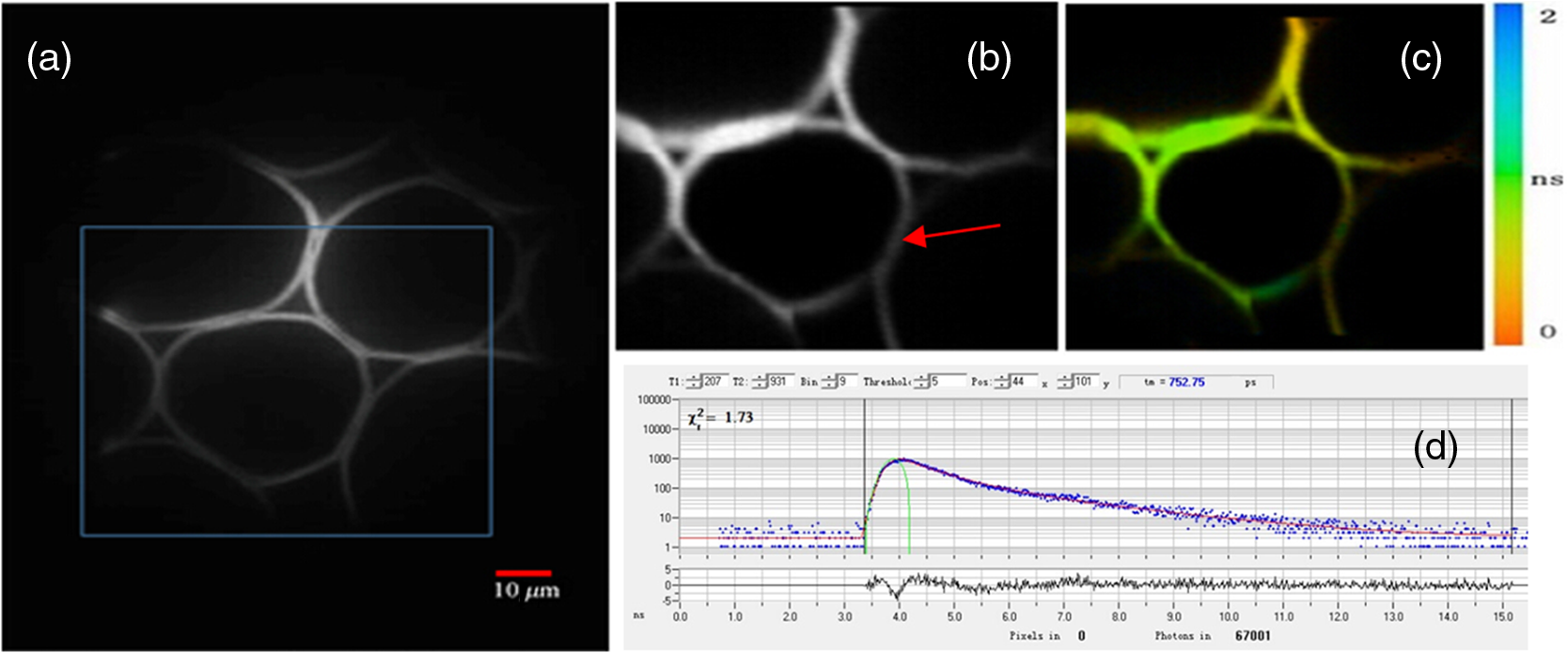 Finally, we used D-FLIM to continuously monitor live HepG2 cells treated with . In our experiment, we first used the fluorescent dye Rhodamine-6G to stain liver cancer HepG2 cells, then we added of to induce apoptosis in the HepG2 cells, and applied the D-FLIM system to dynamically record the fluorescence lifetime of Rhodamine-6G in the HepG2 cells for a certain period of time. Figure 4 shows the D-FLIM images of HepG2 cells treated with . We selected the lower-left HepG2 cells as the representative cell in FOV of fluorescence intensity image, and marked it with a blue square (ROI). The upper left images of Figs. 4(b)–4(e) are fluorescence intensity images at different treatment times and the upper right images are the corresponding fluorescence lifetime images of the ROI, respectively. The lower images of Figs. 4(b)–4(e) are the corresponding histograms of the lifetime distribution. As shown in Fig. 4, the fluorescence lifetime of Rhodamine-6G in the HepG2 cell kept increasing during cell apoptosis, which indicates that our system is able to dynamically monitor the changing process of the ROI in live cells. In order to find out the mechanism underlying the lifetime change, we carried out two sets of additional experiments: one used Rhodamine-6G to immerse liver cancer HepG2 cells without treatment, the other used Rhodamine-6G in a cell culture medium with of but without HepG2 cells. Then, we applied the D-FLIM system to dynamically record the fluorescence lifetime. After analysis, we found that the lifetime in both experiments remained stable during both processes. According to previous reports,4–8,20–24 FLIM can reveal the changes of the micro-environment such as pH, viscosity, and other parameters. We propose that the pH value and the viscosity of cells are changing during cells apoptosis, which may lead to the change of the fluorescence lifetime as shown in Fig. 4. From the experiments, we can also use Rhodamine-6G as a promising probe for monitoring apoptosis in live cancer cells. Fig. 4Dynamic fluorescence lifetime images of HepG2 cells treated with of . (a) Fluorescence intensity image; (b)–(e) fluorescence lifetime images obtained at 10 s, 5 min, 10 min, and 30 min, respectively, after treatment. Also, the average lifetime of (b), (c), (d) and (e) is 889.03, 939.9, 1677.46, and 2065.83 ps, respectively.  In summary, the D-FLIM system provides an effective way to monitor the micro environment of specific live cells. When combined with the dye Rhodamine-6G, our D-FLIM system is able to monitor the apoptosis process in liver cells. In view of the above advantages, the D-FLIM system has potentially wide spread applications in biological and biomedical research fields. AcknowledgmentsThis work has been partially supported by the National Basic Research Program of China (Grant Nos. 2015CB352005 and 2012CB825802), National Natural Science Foundation of China (61378091, 11204226, and 61405123), Shenzhen Science and Technology Development Project (ZDSY20120612094247920, JCYJ20130329114905559, and CXB201104220021A), and China Postdoctoral Science Foundation (2014M552226). ReferencesJ. Quet al.,
“Recent progress in multifocal multiphoton microscopy,”
J. Innovative Opt. Health Sci., 5
(3), 1250018
(2012). http://dx.doi.org/10.1142/S1793545812500186 JIOHAA 1793-7205 Google Scholar
J. Qiet al.,
“Fast flexible multiphoton fluorescence lifetime imaging using acousto-optic deflector,”
Opt. Lett., 38
(10), 1697
–1699
(2013). http://dx.doi.org/10.1364/OL.38.001697 OPLEDP 0146-9592 Google Scholar
J. E. Solomon,
“Polarization imaging,”
Appl. Opt., 20
(9), 1537
–1544
(1981). http://dx.doi.org/10.1364/AO.20.001537 APOPAI 0003-6935 Google Scholar
J. A. Levittet al.,
“Fluorescence lifetime and polarization-resolved imaging in cell biology,”
Curr. Opin. Biotechnol., 20
(1), 28
–36
(2009). http://dx.doi.org/10.1016/j.copbio.2009.01.004 CUOBE3 0958-1669 Google Scholar
H. J. LinP. HermanJ. R. Lakowicz,
“Fluorescence lifetime-resolved pH imaging of living cells,”
Cytometry A, 52 77
–89
(2003). http://dx.doi.org/10.1002/(ISSN)1097-0320 1552-4922 Google Scholar
A. V. AgronskaiaL. TertoolenH. C. Gerritsen,
“High frame rate fluorescence lifetime imaging,”
J. Phys. D, 36 1655
–1662
(2003). http://dx.doi.org/10.1088/0022-3727/36/14/301 JPAPBE 0022-3727 Google Scholar
J. A. Levittet al.,
“Fluorescence lifetime imaging of molecular rotors to map microviscosity in cells,”
Chin. Opt. Lett., 8
(10), 926
–930
(2010). http://dx.doi.org/10.3788/COL COLHBT 1671-7694 Google Scholar
K. Suhlinget al.,
“Fluorescence lifetime imaging of molecular rotors in living cells,”
J. Visualized Exp.,
(60), e2925
(2012). http://dx.doi.org/10.3791/2925 JVEOA4 1940-087X Google Scholar
W. Zhonget al.,
“Picosecond-resolution fluorescence lifetime imaging microscopy: a useful tool for sensing molecular interactions in vivo via FRET,”
Opt. Express, 15
(26), 18220
–18235
(2007). http://dx.doi.org/10.1364/OE.15.018220 OPEXFF 1094-4087 Google Scholar
D. M. JamesonC. M. VetromileN. G. James,
“Investigations of protein-protein interactions using time-resolved fluorescence and phasors,”
Methods, 59 278
–286
(2013). http://dx.doi.org/10.1016/j.ymeth.2013.01.004 MTHDE9 1046-2023 Google Scholar
T. B. Krasievaet al.,
“Two-photon excited fluorescence lifetime imaging and spectroscopy of melanins in vitro and in vivo,”
J. Biomed. Opt., 18
(3), 031107
(2013). http://dx.doi.org/10.1117/1.JBO.18.3.031107 JBOPFO 1083-3668 Google Scholar
Y. Shaoet al.,
“Ultrafast, large-field multiphoton microscopy based on an acousto-optic deflector and a spatial light modulator,”
Opt. Lett., 37
(13), 2532
–2534
(2012). http://dx.doi.org/10.1364/OL.37.002532 OPLEDP 0146-9592 Google Scholar
Y. Shaoet al.,
“Addressable multiregional and multifocal multiphoton microscopy based on a spatial light modulator,”
J. Biomed. Opt., 17
(3), 030505
(2012). http://dx.doi.org/10.1117/1.JBO.17.3.030505 JBOPFO 1083-3668 Google Scholar
J. D. LechleiterD. T. LinI. Sieneart,
“Multi-photon laser scanning microscopy using an acoustic optical deflector,”
Biophys. J., 83
(4), 2292
–2299
(2002). http://dx.doi.org/10.1016/S0006-3495(02)73989-1 BIOJAU 0006-3495 Google Scholar
R. D. Roordaet al.,
“Video-rate nonlinear microscopy of neuronal membrane dynamics with genetically encoded probes,”
J. Neurophysiol., 92
(1), 609
–621
(2004). http://dx.doi.org/10.1152/jn.00087.2004 JONEA4 0022-3077 Google Scholar
P. A. Kirkbyet al.,
“A compact acousto-optic lens for 2D and 3D femtosecond based 2-photon microscopy,”
Opt. Express, 18
(13), 13721
–13745
(2010). http://dx.doi.org/10.1364/OE.18.013720 OPEXFF 1094-4087 Google Scholar
X. Lvet al.,
“Construction of multiphoton laser scanning microscope based on dual-axis acousto-optic deflector,”
Rev. Sci. Instrum., 77 046101
(2006). http://dx.doi.org/10.1063/1.2190047 RSINAK 0034-6748 Google Scholar
V. IyerB. E. LosavioP. Saggau,
“Compensation of spatial and temporal dispersion for acousto-optic multiphoton laser-scanning microscopy,”
J. Biomed. Opt., 8
(3), 460
–471
(2003). http://dx.doi.org/10.1117/1.1580827 JBOPFO 1083-3668 Google Scholar
S. Zenget al.,
“Simultaneous compensation for spatial and temporal dispersion of acousto-optical deflectors for two-dimensional scanning with a single prism,”
Opt. Lett., 31
(8), 1091
–1093
(2006). http://dx.doi.org/10.1364/OL.31.001091 OPLEDP 0146-9592 Google Scholar
G. D. Reddyet al.,
“Three-dimensional random access multiphoton microscopy for functional imaging of neuronal activity,”
Nat. Neurosci., 11
(6), 713
–720
(2008). http://dx.doi.org/10.1038/nn.2116 NANEFN 1097-6256 Google Scholar
W. Beckeret al.,
“High-speed FLIM data acquisition by time-correlated single photon counting,”
Proc. SPIE, 5323 27
–35
(2004). http://dx.doi.org/10.1117/12.529113 PSISDG 0277-786X Google Scholar
W. Beckeret al.,
“Advanced time-correlated single photon counting technique for spectroscopy and imaging in biomedical system,”
Proc. SPIE, 5340 104
–112
(2004). http://dx.doi.org/10.1117/12.529143 PSISDG 0277-786X Google Scholar
G. A. Hungerfordet al.,
“Monitoring sol-to-gel transitions via fluorescence lifetime determination using viscosity sensitive fluorescent probes,”
J. Phys. Chem. B, 113
(35), 12067
–12074
(2009). http://dx.doi.org/10.1021/jp902727y JPCBFK 1520-6106 Google Scholar
J. A. Levittet al.,
“Membrane-bound molecular rotors measure viscosity in live cells via fluorescence lifetime imaging,”
J. Phys. Chem. C, 113
(27), 11634
–11642
(2009). http://dx.doi.org/10.1021/jp9013493 1932-7447 Google Scholar
BiographyWei Yan received his PhD degree from the Wuhan National Laboratory for Optoelectronics, Huazhong University of Science and Technology, China. He is currently a postdoctoral fellow at Shenzhen University, China. Xiao Peng received her PhD degree from the Department of Applied Biology and Chemical Technology, Hong Kong Polytechnic University in 2007. She is currently a lecturer in the College of Optoelectronic Engineering at Shenzhen University. Jing Qi received his BS degree in biomedical engineering from Henan University of Science and Technology, China. He is currently a PhD student fellow in the College of Optoelectronic Engineering, Shenzhen University, China. Jian Gao received her BS degree in physics from Anqing Normal University, China. She is currently a third-year graduate student in the College of Optoelectronic Engineering, Shenzhen University (the Key Laboratory of Optoelectronic Devices and Systems of Guangdong Province). Shunping Fan is currently a master’s student in the College of Optoelectronic Engineering, Shenzhen University in China. Qi Wang received his bachelor’s degree from the College of Optoelectronic Engineering, Shenzhen University, in 2007. He is currently a graduate student in the College of Optoelectronic Engineering at Shenzhen University. Junle Qu received his PhD degree from the Department Xi’an Institute of Optics and Precision Mechanics, Chinese Academy of Sciences in 1998. He is currently a professor in the College of Optoelectronic Engineering at Shenzhen University, and his research focuses on biomedical optical imaging and its application in monitoring cell processes and cell-drug interactions. Hanben Niu graduated from the Department of Radio-electronics at Tsinghua University in 1966. He is currently an academician of the Chinese Academy of Engineering, and a professor in the College of Optoelectronic Engineering at Shenzhen University. His research field includes superresolution fluorescence imaging, x-ray phase contrast imaging, and ultrafast phenomenon diagnosis. |


