
|
|
1.IntroductionThe creation of optical implants that provide clear vision at near, intermediate, and far distances remains an important aim for optical and medical scientists. These implants are often based on multifocal diffractive optical elements (DOEs) which create a prescribed set of foci corresponding to different vision distances. The design and fabrication of such DOEs are useful for medical applications such as multifocal contact and intraocular lenses (IOLs).1,2 Although the current bifocal IOLs design has proven to be a valuable standard for wide practical applications, its use at present is largely limited by the relatively high costs of such lenses (manufactured, e.g., using the diamond cryolathing process) and insufficient clearness of sight at intermediate distances for bifocal IOLs. World manufacturers of the diffractive–refractive IOLs are mainly using diffraction relief with the triangular profile. Recently, several trifocal IOLs have been introduced to the marketplace. For example, the FineVision (PhysIOL, Liège, Belgium) is a multifocal lens that combines two diffractive kinoform patterns (one with a 3.50 D addition for near vision and one with a 1.75 D addition for intermediate vision with its second focus at 3.50 D adding to the near vision addition).3 The main feature of this trifocal lens design is a significant improvement in intermediate vision. A possible way to overcome the problem of intermediate distance vision by means of trifocal lens optical features is proposed by Valle et al.4 Special attention is paid to the control of the added optical powers and the relative intensity of every focus. Recently, the designs of radial profiles of the trifocal zone plates with binary and sine transformation functions have been proposed and the possibility of the realization of the trifocal 2.7 mm binary diffractive optical elements has been demonstrated.5 It has been shown that the fabrication of concentric binary rings with heights of about 300 nm using commercially available photoresists is possible by means of the application of a modern laser technique—two-photon polymerization (2PP), which is a unique instrument for the fabrication of arbitrary three-dimensional structures with subwavelength resolution (see, for example, Refs. 67. to 8 and references therein). This technique has been applied for the fabrication of multilevel-phase-encoded DOE in inorganic–organic hybrid polymer material.9 However, the used scanning speed was about , which resulted in a total fabrication time of a couple of hours for a DOE with the size of . Previously, it has been demonstrated that ultraviolet (UV) nanoimprinting is a powerful instrument for the rapid manufacturing of nanostructured films.10–14 Nanoimprinting technology is based on direct mechanical deformation of the resist film and can achieve resolutions beyond the limitations set by light diffraction or beam scattering, which are intrinsic for conventional lithographic techniques. The resolution of nanoimprinting mainly depends on the minimum mold feature size that can be fabricated. In comparison with optical lithography, it makes nanoimprinting capable of producing sub-10 nm features over a large area with a high throughput and low cost.15 For example, Toshiba has validated it for the feature size of 22 nm and beyond.16 The high resolution and relatively low costs of nanoimprinting make it attractive for the fabrication of DOEs with continuous and binary microreliefs. These DOEs can be applied for the generation of any desired longitudinal intensity distributions (coaxial lines, sets of sequential axial foci, etc.) required for different optical applications. The present paper is devoted to the application of the UV nanoimprinting technique for the fabrication of submicron-height sine-like relief of a trifocal zone plate. The realized trifocal lens consists of a conventional thin lens with a fixed focus and a trifocal zone plate. It should be noted that, if required, a nonuniform distribution of the light intensity between the foci (e.g., with increased intensity in near or far vision focus) can be achieved by proper design and fabrication of the sine-like profile of the diffractive relief, which can give a range of clear vision for persons of certain professions. It is known that the same structures can be produced by traditional fabrication systems based on diamond turning or e-beam writing. Compared to these systems, nanoimprinting allows the rapid and economic mass production of multifocal IOLs. 2.Design of Diffractive Lenses for Three-Focus Longitudinal Intensity DistributionsA general method for designing multifocal diffractive lenses used in the present work was described in Refs. 5 and 17. For the sake of consistency, we briefly repeat the basic equations. Let us consider an incident beam with the complex amplitude given by where is the radial coordinate in the lens plane. In this case, the phase function of the multifocal lens takes the form where is the lens aperture radius and the functions , are the phase functions of lenses with some focal lengths and and in the paraxial case are given by where is the wavenumber. The function in Eq. (2) performs a nonlinear transformation of the phase function . In the case when the incident beam has a plane wavefront (i.e., ), the multifocal lens can be represented as a superposition of a conventional lens and a zone plate with the phase functions and , respectively. The nonlinear function in Eq. (2) generates additional diffraction orders.18 The energy distribution between the orders is determined by the particular form of this function. Thus, the complex amplitude of the beam transmitted through the multifocal lens can be represented as the following superposition of spherical beams:5,17 where are the beam foci and are the Fourier coefficients of the function .According to Eq. (4), the energy distribution between the beams is given by the values , . In the case of the trifocal lens, the nonlinear transformation function can be defined as a sine function:5 The multiplicative constant in Eq. (7) was chosen so that . Hence, if the nonlinear transformation function is defined by Eq. (7), 90% of the energy of the incident beam will be concentrated in the three desired beams with the foci , . For the considered trifocal lens, the energy distribution between foci is constant. Note that the choice of the nonlinear transformation function can provide any required energy distribution between foci. In the framework of the scalar diffraction theory, the diffraction efficiencies of the orders of a phase diffraction grating are proportional to the squared absolute values of the Fourier coefficients of the complex transmittance function.18 Thus, to form an energy distribution , in the corresponding foci , the function is determined as the phase function of a diffraction grating with period and diffraction orders intensities , .17 The grating calculation can be carried out by means of the Gerchberg–Saxton algorithm or gradient methods.18 As an example, Fig. 1(a) shows the nonlinear transformation function with a linear energy distribution in the diffraction orders: Fig. 1(a) Phase functions of three-order diffraction gratings with linear energy distribution (blue solid line) and initial sinusoidal function (green dashed line). (b) The intensity distribution between diffraction orders (squared absolute values of the Fourier coefficients) for the considered grating.  This function was calculated using the Gerchberg–Saxton algorithm. The sine function (7) also shown in Fig. 1(a) was used as the initial approximation. The squared absolute values of the Fourier coefficients of the calculated function are shown in Fig. 1(b), where , , . According to Fig. 1(b), the calculated grating forms the predetermined linear distribution with a high precision and concentrates more than 90% of energy in the desired orders. The multifocal lens with the phase function of Eq. (2) can be implemented either as a single DOE with complex diffractive microrelief or as a combination of two elements: a conventional refractive lens with focus and a diffractive zone plate . In the present work, the latter approach was chosen. In the simplest case, the refractive lens corresponds to a plano-convex lens with the curvature radius , where is the refractive index of the lens material. The zone plate profile is given by where is the refractive index of the plate material.As an example, we designed a trifocal lens of Eq. (2) for the following parameters: , , , lens aperture radius , . For the listed parameters, the values , are 43.4, 50, and 58.9 mm, respectively. Let us note that the position of the central focus can be controlled by a proper choice of the refractive lens focus value , while the distance between adjacent foci is defined by the value. Indeed, according to Eq. (4), the optical powers of the zone plate orders given by the values , are added to the optical power of the refractive lens , thus generating three foci. To demonstrate the possibility of generating the desirable predetermined energy distribution between the foci (increasing or decreasing), the calculated phase function of the grating with linear intensity distribution between diffraction orders [blue solid line in Fig. 1(a)] was used as the function . The zone plate profile defined by Eq. (9) and corresponding to that function is shown in Fig. 2 (blue solid line). The black dotted line in Fig. 2 depicts the estimated profile of the fabricated zone plate recovered from the intensity measurements and is described below in Sec. 4. Fig. 2Radial profile of the designed trifocal zone plate with linear energy distribution between foci (blue solid line) and the profile estimated from the registered longitudinal intensity distribution (black dotted line).  The intensity distribution generated by the lens with the phase function can be calculated using the Fresnel–Kirchhoff diffraction integral:18 where denotes the coordinate along the optical axis. The normalized intensity distribution along the optical axis is shown in Fig. 3 and demonstrates high-quality focusing into three spots. Let us note that the focal intensity peaks in Fig. 3 are not described by a linear function of Eq. (8). This is explained by the fact that the intensity in the geometric focus is in inverse proportion to the squared focal length, which is why the intensity values at the focal peaks are defined by the equation . At the same time, the illuminated beam energy portions focused in the diffraction vicinity of the radius , are in almost perfect agreement with Eq. (8) for the required planes .In our previous work, the binary zone plate was successfully realized by means of the 2PP technique,5 whose precision is near to 100 nm. The present paper is devoted to the application of the UV nanoimprinting for the fabrication of designed sine-like relief of a trifocal diffractive zone plate (Fig. 2). 3.Experimental Setup and MaterialsFor the fabrication of the diffractive microrelief, the proper UV nanoimprinting mold needs to have high stiffness in order for the nano-sized protrusion patterns to be transferred to the substrate. A sufficiently low surface energy is also necessary to avoid the need for an anti-sticking coating on the mold, such as a fluorinated polymer layer.10 In this study, for the fabrication of microstructured mold with circular symmetry, we apply a Ni-plated diamond-turned aluminum mold, manufactured by the courtesy of NiPro Optics according to our computer-simulated design. The mold diameter is 12.7 mm, the thickness is 4 mm, and the diameter of the microstructured area is 5 mm. A commercially available photoresist SU-8 2000.5 (Chestech Ltd., United Kingdom) was used as an imprint material. The glass transition temperature of uncrosslinked SU-8 is 60°C, making it suitable for a low-temperature imprint process. Thermal-imprint tests were performed with desktop equipment, which is designed to imprint samples with a 12.7 mm diameter. The available maximum heating temperature for press-punch is 200°C, and the maximum press force is 2 kgf. The photoresist film was deposited on cleaned and dried quartz substrates with diameter 12.7 mm and thickness 4 mm. After deposition of SU-8, the samples were prebaked on a hot plate at 95°C for 30 min to evaporate the solvent and densify the film. Prior to imprinting, the surface of the polymer film was then pretreated by UV exposure for 10 s (Thorlabs High Power UV Curing LED System CS2010, collimated UV radiation power is ). The procedures of the imprint process adopted in this study were as follows. In the first step, the mold was pressed into the SU-8 resist at set temperature (well above the glass transition temperature of uncured SU-8; 60°C) to physically deform the resist shape such that it conformed to the topology of the mold. The imprinting temperature condition for uncured SU-8 has been reported elsewhere and a rule of thumb is that the imprint temperature should be set below 95°C to prevent degassing. Imprinting temperatures that are higher than the prebake temperature can cause the degassing phenomena. To achieve a uniform distribution of pressure over the entire sample surface, a polymer spacer was inserted between the SU-8 sample and the mold surface. The pressing force was then maintained for a sufficient time () to achieve complete filling. This hold time is the function of both the material temperature and pressing force. After cooling to , the applied pressure was released and the Ni-plated mold was removed from the SU-8 resist in the uncured state. In the final step, the imprinted SU-8 resist was postcured with exposure to UV light (1 min) and subsequent baking at 95°C for 3 min. 4.Experimental ResultsThe sine-like diffractive relief with a 5-mm diameter providing linear energy distribution between the foci (Fig. 2, blue solid line) was fabricated on the SU-8 resist film and the realized microstructured surface was investigated by means of SEM and AFM microscopy. The results of the microrelief characterization are presented in Fig. 4. Fig. 4Scanning electron microscope (SEM) (a) and atomic force microscope (AFM) (b) views of the fabricated DOE’s surface with sine-like radial relief. 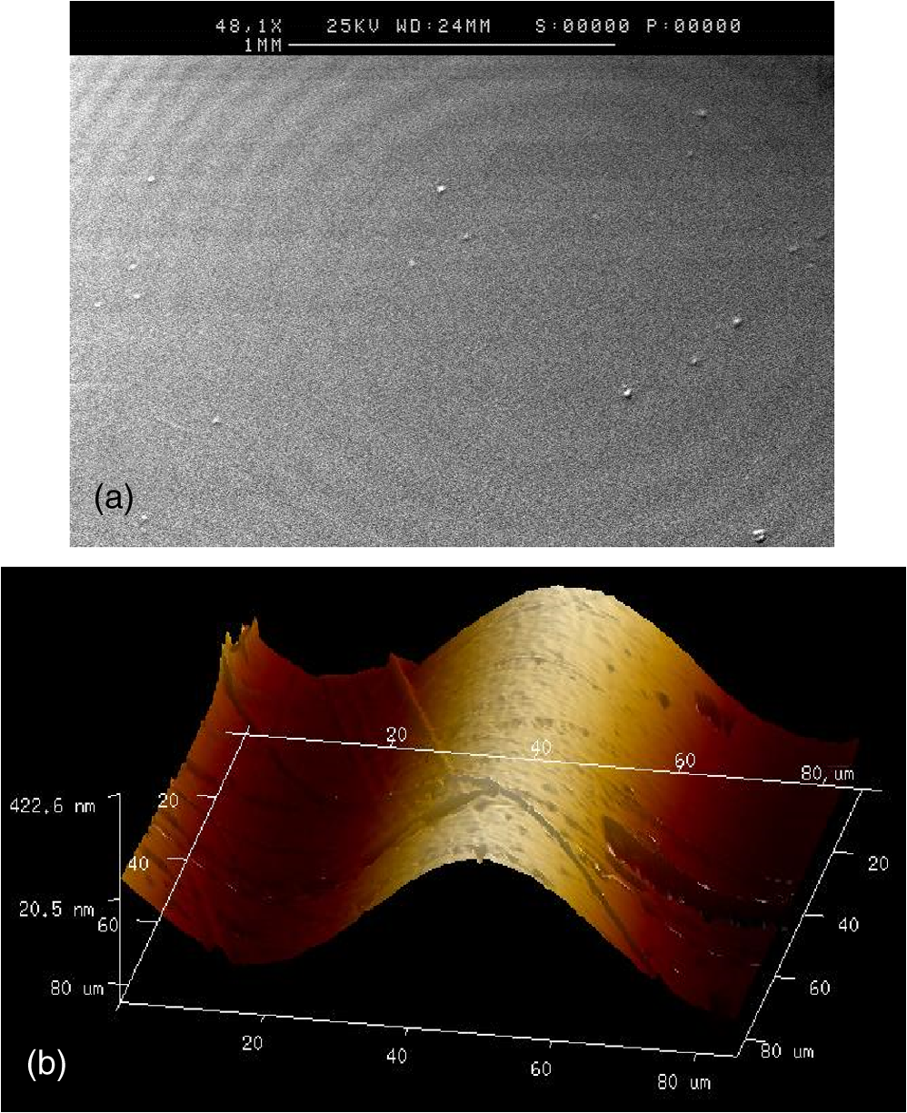 The optical setup presented in Fig. 5 was used for the investigation of the focusing properties of the fabricated diffractive optical element, where a Thorlabs continuous wave He–Ne laser with a beam diameter of 1 mm was used as an illuminating source. The illuminating laser beam was consequently passed through the neutral filter, spatial filter Thorlabs KT110M consisting of two lenses and a pinhole, 5X telescope, and 5-mm diaphragm with the aim to form a transverse intensity distribution close to a plane wave. The experimentally realized trifocal lens consisted of a 4-mm quartz substrate with the diffraction microrelief shown in Fig. 2, fabricated by the nanoimprinting technique on the SU-8 film, and the commercial quartz lens with a 50-mm focus. The laser intensity distributions formed at the different distances from the trifocal lens were registered by IDS UI-1480-M/C CCD camera, which was installed on the optical platform and scanned along the longitudinal optical axis by means of a micrometric screw. The registered transverse intensity distributions were analyzed by specially designed software for maximum intensity determination near the optical axis. The longitudinal intensity distribution generated by the lens under consideration along the optical axis is presented in Fig. 6 (blue solid line) and demonstrates formation of three sharp foci located at the designed positions. At the same time, there are some discrepancies between the calculated and registered intensity distributions (Figs. 3 and 6). The registered peaks are broader and have different intensities than in the theoretically calculated distribution in Fig. 3. Fig. 6Registered longitudinal intensity distribution formed by the fabricated lens (blue solid line), and the theoretical distribution calculated for the estimated zone plate (black dotted line in Fig. 2) with the spherical aberration (black dotted line).  The increased peak widths mainly result from the spherical aberration of the refractive spherical lenses used in the experimental setup. Indeed, apart from the spherical lens combined with the trifocal zone plate, both the telescope and the filter contain two lenses each (Fig. 5). To check this assumption, we repeated the theoretical calculations [Eq. (10)] introducing the term representing the spherical aberration into the phase function of the trifocal lens. In this case, a reasonable agreement with the widths of the registered peaks was obtained at . The different peak intensities may be explained by the defects in the fabricated zone plate profile. According to Eq. (4), the energy distribution between the foci is defined by the function , in Eq. (2). Therefore, to estimate the fabricated profile we modified the function to fit the registered longitudinal intensity distribution. The estimated profile is shown by the black dotted line in Fig. 2. Comparison of the plots in Fig. 2 suggests that the manufactured zone plate has an error with a height of about 50 nm. The theoretical intensity distribution computed using Eq. (10) with the modified function and introduced spherical aberration is depicted in Fig. 6 by the black dotted line and demonstrates good agreement with the experimental distribution. The achieved agreement confirms the presented explanation of the discrepancies between the theoretical and registered intensity distributions (Figs. 3 and 6). The transverse intensity distributions measured in the three focal planes are shown in Figs. 7(a) to 7(c). For comparison, Fig. 7(d) shows the intensity profiles measured along the coordinate axes at the central focal plane and the theoretical profile calculated taking into account the introduced spherical aberration. According to Fig. 7(d), the measured peak width is in good agreement with the calculations. Similar agreement also takes place in two other focal planes. Fig. 7Registered transverse intensity distributions formed by the fabricated lens in three main focal planes [(a)–(c)]. Intensity profiles measured along the Ox (blue solid line) and Oy (green dashed line) coordinate axes at the central focal plane and the theoretical profile calculated taking into account the introduced spherical aberration (black dotted line) (d).  In this work, we fabricated the designed zone plate with a 5-mm diameter in less than 30 min, using a one-mold imprinting system. Application of a multimold system can significantly (more than several times) reduce the fabrication time of such DOE-based ophthalmic implants. 5.Effects of Aperture Size and Incident Wavelength ChangeConsidering the application of the studied structure in the design of multifocal contact and intraocular lenses, it is important to analyze the effect of the aperture size change (related to the eye pupil size change due to varying lighting conditions) as well as the wavelength-dependent behavior of the diffractive zone plate. In the current section, we briefly discuss these effects theoretically for the lens designed in Sec. 2. For the sake of simplicity, we do not take into account the spherical aberration introduced in Sec. 4. According to Eq. (4), the designed multifocal lens generates a set of converging spherical beams with foci , [Eq. (5)]. Each focus can be described by the diffraction spot size in the plane perpendicular to the optical axis (transverse spot size ) and along the optical axis (longitudinal spot size ) which are given by18 Moreover, one can obtain from Eqs. (4), (10), and (11) that the intensities in the focal peaks are proportional to the following values: where are the Fourier coefficients of the function [Eq. (6)]. According to Eqs. (11) and (12), the spot sizes , are in inverse proportion to the lens radius and to the squared lens radius, respectively. In turn, the intensities in the focal peaks are inversely proportional to the squared transverse spot sizes.For the considered parameters, the values of , are equal to 0.77 mm, 1 mm, and 1.37 mm, respectively (Fig. 3). If the aperture radius is decreased from 2.5 to 1.5 mm, the take the values of 2.1, 2.8, and 3.8 mm, respectively. Let us now consider the performance of the studied lens at different wavelengths. The lens was designed for the operation at . This wavelength is relatively far from the central wavelength of the photopic eye spectral sensitivity () and was chosen because of the available experimental facilities. The operation of the used trifocal diffractive zone plate [Eq. (9)] is wavelength dependent. The change of the wavelength results in the change of the foci position and the energy distribution between the foci. It can be shown that at wavelength , the field generated by the multifocal lens still corresponds to a set of spherical beams in Eq. (4) while the beam foci positions and the Fourier coefficients are now given by the following modified equations: Equations (13) and (14) were obtained under the assumption that the influence of the material dispersion is negligible in comparison with the chromatic aberration of the zone plate. As an example, Fig. 8 shows the longitudinal intensity distributions at three wavelengths: 580, 630 (the design wavelength), and 680 nm. In accordance with Eq. (13), Fig. 8 shows that the location of the central focus (generated by the conventional nondiffractive lens) remains constant while the other foci are shifted along the optical axis with respect to their original positions at . Such chromatic aberration is typical for diffractive lenses including available IOLs with diffractive microrelief.5,17,19,20 It was shown that despite relatively high chromatic aberrations, multifocal diffractive structures are widely used in commercially available refractive–diffractive IOLs, e.g., in lenses ReSTOR (Alcon Laboratories, Inc.) and Tecnis (Abbott Medical Optics, Inc.) families. In particular, the IOLs such as Tecnis ZM900 and ReSTOR SN60D3 function well in the human eye because the amount of the chromatic aberration is approximately the same, albeit with opposite sign, as the aberration in the refractive part of the eye (cornea and the refractive part of the IOL).19,20,21 Fig. 8Calculated intensity distributions along the optical axis at (blue line), at the design wavelength (green line), and at (red line) normalized by maximal intensity at . 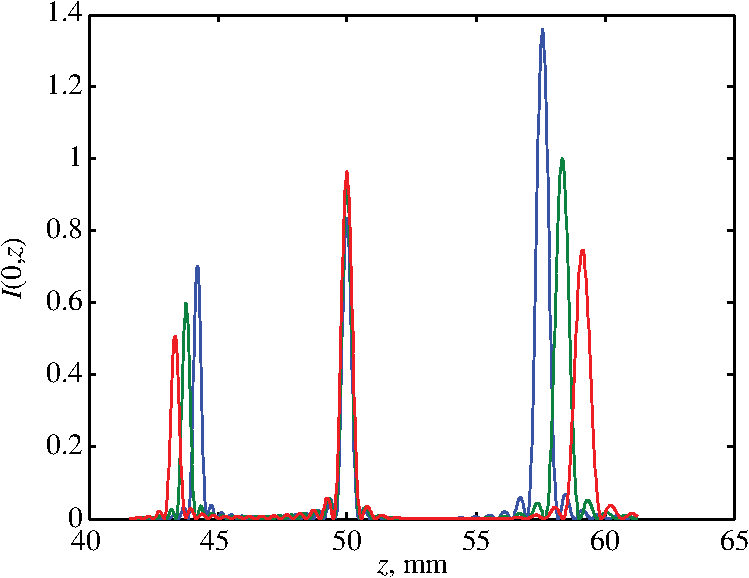 According to Eqs. (4) and (14), the energy distribution between the foci in Fig. 8 is given by the values , . Let us note that although the energy distribution between the foci changes, the total energy concentrated in the three desired diffraction orders of the zone plate (i.e., in the three desired foci) remains almost constant and is close to 90%. The authors believe that lenses having a specified energy distribution between foci in a prescribed wavelength range can be designed using a more complex nonlinear transformation function corresponding to a sophisticated diffractive relief. This problem will be addressed in a future work. 6.ConclusionIn the present work, the ability of a UV nanoimprinting technique to fabricate a trifocal sine-like zone plate with a 5-mm diameter and optical powers , , has been demonstrated. It has been shown that the fabrication of concentric rings with a sine-like radial profile at heights of approximately 450 nm from commercially available photoresists is possible. The performed investigations of the optical properties of the realized trifocal lens have demonstrated that experimental results are in good agreement with the numerical design. It is important to note that the UV nanoimprinting technique may be used for the fabrication of DOEs forming multifocus longitudinal intensity distributions for a wide range of biomedical applications and other imaging systems. The trifocal IOLs with a sine-like profile are expected to be more biocompatible because of the reduction of the debris precipitation effect, which takes place in IOLs with a triangular profile after long-term use. AcknowledgmentsWe would like to gratefully acknowledge ERDF grant 080/P1/021. Theoretical part of this work was funded by the Russian Science Foundation grant 14-19-00796. ReferencesA. L. Cohen,
“Practical design of a bifocal hologram contact lens or intraocular lens,”
Appl. Opt., 31
(19), 3750
–3754
(1992). http://dx.doi.org/10.1364/AO.31.003750 APOPAI 0003-6935 Google Scholar
M. J. Simpson,
“Diffractive multifocal intraocular lens image quality,”
Appl. Opt., 31
(19), 3621
–3626
(1992). http://dx.doi.org/10.1364/AO.31.003621 APOPAI 0003-6935 Google Scholar
D. Gatinel et al.,
“Design and qualification of a diffractive trifocal optical profile for intraocular lenses,”
J. Cataract Refract. Surg., 37 2060
–2067
(2011). http://dx.doi.org/10.1016/j.jcrs.2011.05.047 JCSUEV 0886-3350 Google Scholar
P. J. Valle et al.,
“Visual axial PSF of diffractive trifocal lenses,”
Opt. Express, 13
(7), 2782
–2792
(2005). http://dx.doi.org/10.1364/OPEX.13.002782 OPEXFF 1094-4087 Google Scholar
V. Osipov et al.,
“Fabrication of three-focal diffractive lenses by two-photon polymerization technique,”
Appl. Phys. A, 107
(3), 525
–529
(2012). http://dx.doi.org/10.1007/s00339-012-6903-9 APAMFC 0947-8396 Google Scholar
S. Kawata et al.,
“Finer features for functional microdevices,”
Nature, 412
(6848), 4675
–4680
(1997). http://dx.doi.org/10.1038/35089130 NATUAS 0028-0836 Google Scholar
J. Serbin et al.,
“Femtosecond laser-induced two-photon polymerization of inorganic organic hybrid materials for applications in photonics,”
Opt. Lett., 28
(5), 301
–303
(2003). http://dx.doi.org/10.1364/OL.28.000301 OPLEDP 0146-9592 Google Scholar
J. Serbin, A. Ovsianikov and B. Chichkov,
“Fabrication of woodpile structures by two-photon polymerization and investigation of their optical properties,”
Opt. Express, 12
(21), 5221
–5228
(2004). http://dx.doi.org/10.1364/OPEX.12.005221 OPEXFF 1094-4087 Google Scholar
B. Jia et al.,
“Use of two-photon polymerization for continuous gray-level encoding of diffractive optical elements,”
Appl. Phys. Lett., 90 073503
(2007). http://dx.doi.org/10.1063/1.2426923 APPLAB 0003-6951 Google Scholar
L. J. Guo,
“Recent progress in nanoimprint technology and its applications,”
J. Phys. D: Appl. Phys., 37 R123
–R141
(2004). http://dx.doi.org/10.1088/0022-3727/37/11/R01 JPAPBE 0022-3727 Google Scholar
K. Okuda et al.,
“Hybrid nanoimprint for micro-nano mixture structure,”
Proc. SPIE, 6533 65330R1
(2007). http://dx.doi.org/10.1117/12.736928 PSISDG 0277-786X Google Scholar
S.-W. Youn et al.,
“Microstructuring of SU-8 photoresist by UV-assisted thermal imprinting with non-transparent mold,”
Microelectron. Eng., 85 1924
–1931
(2008). http://dx.doi.org/10.1016/j.mee.2008.06.016 MIENEF 0167-9317 Google Scholar
R. Liu et al.,
“Optical nanostructures fabricated by SU-8 based nanoimprint lithography,”
J. Korean Phys. Soc., 55
(3), 1290
–1294
(2009). http://dx.doi.org/10.3938/jkps.55.1290 KPSJAS 0374-4884 Google Scholar
J.-H. Shin et al.,
“Fabrication of flexible UV nanoimprint mold with fluorinated polymer-coated PET film,”
Nanoscale Res. Lett., 6 458
(2011). http://dx.doi.org/10.1186/1556-276X-6-458 1556-276X Google Scholar
Y. Chou et al.,
“Sub-10 nm imprint lithography and applications,”
J. Vac. Sci. Technol. B, 15
(6), 2897
–2904
(1997). http://dx.doi.org/10.1116/1.589752 JVTBD9 0734-211X Google Scholar
I. Yoneda et al.,
“Study of nanoimprint lithography for applications toward 22-nm node CMOS device,”
Proc. SPIE, 6921
(2), 692104
(2008). http://dx.doi.org/10.1117/12.771149 PSISDG 0277-786X Google Scholar
M. A. Golub et al.,
“Computer generated diffractive multi-focal lens,”
J. Mod. Opt., 39
(6), 1245
–1251
(1992). http://dx.doi.org/10.1080/713823549 JMOPEW 0950-0340 Google Scholar
V. Soifer, V. Kotlyar and L. Doskolovich, Iterative Methods for Diffractive Optical Elements Computation, Taylor & Francis, London
(1997). Google Scholar
M. R. de Santhiago et al.,
“A contralateral eye study comparing apodized diffractive and full diffractive lenses: wavefront analysis and distance and near uncorrected visual acuity,”
Clinics, 64
(10), 953
–960
(2009). http://dx.doi.org/10.1590/S1807-59322009001000004 1807-5932 Google Scholar
S. Ravikumar, A. Bradley and L. N. Thibos,
“Chromatic aberration and polychromatic image quality with diffractive multifocal intraocular lenses,”
J. Cataract Refract. Surg., 40 1192
–1204
(2014). http://dx.doi.org/10.1016/j.jcrs.2013.11.035 JCSUEV 0886-3350 Google Scholar
S. S. Lane et al.,
“Multifocal intraocular lenses,”
Ophthalmol. Clin. N. Am., 19 89
–105
(2006). http://dx.doi.org/10.1016/j.ohc.2005.09.002 Google Scholar
BiographyVladimir Osipov graduated from Belarusian State University with a diploma in optics and received his PhD degree in quantum electronics from Stepanov Institute of Physics, Minsk, Belarus. After graduation, he worked at the Stepanov Institute, Jena University, Bayreuth University and Laser Zentrum Hannover, Germany. Currently, he is a visiting researcher at the Aston Institute of Photonic Technologies, Aston University in Birmingham, United Kingdom. His research interests include optical engineering, laser micro- and nanostructuring, and surface characterization. Leonid L. Doskolovich received his BS degree in applied mathematics (with honors) and his PhD and DSc degrees from Samara State Aerospace University, Samara, Russia, in 1989, 1993, and 2001, respectively. Currently, he is a principal researcher with the Image Processing Systems Institute, Russian Academy of Sciences, and a professor with the Technical Cybernetics Department, Samara State Aerospace University, Samara, Russia. His current research interests include diffractive optics, laser information technologies, and nanophotonics. Evgeni A. Bezus received his BS degree in applied mathematics and computer science (with honors) and his PhD degree from Samara State Aerospace University (SSAU), Samara, Russia, in 2009 and 2012, respectively. Currently, he is a researcher with the Image Processing Systems Institute, Russian Academy of Sciences, and an assistant professor with the Technical Cybernetics Department, Samara State Aerospace University, Samara, Russia. His current research interests include nanophotonics, plasmonics, grating theory, and diffractive optics. Tom Drew is a researcher in the Ophthalmic Research Group at Aston University. His research interests include accommodating and multifocal intraocular lenses and development of new optical implants. Kaiming Zhou has been a research fellow at Aston University since 2002. His research interests are to couple light out of the optical fiber using tilted gratings to realize the function of optical spectral analyzers. Other interests include fiber Bragg grating, optical fiber sensors, and semiconductor lasers. Kameel Sawalha joined Aston University in 1985 as a PhD student. After completing his PhD degree in 1990 he worked as a senior research engineer, working on industrial projects. As a visiting professor, he currently supervises students at Aston at the master’s level across a range of programs with the Schools of Engineering and Applied Science and also Life and Health Sciences. He is also a visiting professor of materials at Sakarya University in Turkey. Greg Swadener received his PhD degree in engineering mechanics from the University of Texas at Austin. He is currently MSc program director in mechanical engineering (modelling) at Aston University. His experience includes 20 years in industry and research, most recently as a staff scientist with the Center for Integrated Nanotechnologies at Los Alamos National Laboratory. His research in the areas of biomechanics and nanomechanics has featured nanoindentation, finite element methods, and molecular dynamics. James S. W. Wolffsohn is the professor and deputy executive dean of the Life and Health Sciences School and Ophthalmic Research Group at Aston University. His research interests include accommodating and multifocal intraocular lenses, intraocular lens trials, contact lenses and tear film, and development of new optical instrumentation. |


