|
|
1.IntroductionRadiotherapy treatments are almost entirely based on high-intensity photon radiation ( and rays) and electron radiation, emitted by expensive linear particle accelerators, requiring extensive space and radiation protection for the patients and the medical personnel. Radiation therapy is based on damaging the DNA in the irradiated cells. Therefore, it does not discriminate between healthy and malignant tissues. As a result, side effects commonly occur, ranging from skin burns to critical damage to internal organs, causing patient discomfort and potential health hazards.1 In order to reduce the side effects, careful patient-specific radiation preliminary planning is performed. However, this is limited by the natural radiation propagation patterns in tissues. High-intensity photon radiation, which is the most common type of radiotherapy used, affects all the tissues in its path, from the skin to the tumor and beyond. On the other hand, electron radiation has a steep cut-off of the effective-dose curve and, therefore, affects cells from the surface tissue to a maximal penetration depth, determined by electron energy. After reaching this depth, most of the electron’s energy is lost, and the radiation is no longer effective, thus allowing minimal damage to healthy surrounding tissues.1 Due to this characteristic, this type of radiation is preferred only for superficial tumors, such as nose, scalp, or neck tumors surrounded by sensitive healthy tissues. It has been in use since the 1950s. However, its applicability for deeper tissues is limited, since electron beams can only be projected on the relevant tissue externally, as there is no method to transport the electrons to internal tissues. The concept of particle acceleration by high-intensity lasers has been the focus of extensive research since its introduction in 1979.2 The rapid development of lasers and the increase of laser intensity3 have brought these accelerators from theory to realization.4,5 More specifically, high-intensity lasers can be used to accelerate electrons to energies required for electron radiotherapy needs, in a considerably smaller space and at a reduced cost.6–8 Although some difficulties remain to be resolved, the integration of these systems to widespread medical use is closer than ever.9–13 As mentioned, particle trajectory cannot be conveniently manipulated as it is done with laser illumination. Current research focuses on the use of laser accelerators as an external radiation source. However, it can be useful to develop a method for internal radiation, thus reducing the side effect since less healthy tissues will be exposed to the radiation. This method is based on the idea of leading the intense laser radiation to the vicinity of the tumor and performing the acceleration there. This task is quite difficult due to the high intensities involved. However, the recent development and continual improvement of waveguides suitable for high-intensity laser transmission14,15 can be used to accomplish this goal. Nevertheless, the use of high-intensity laser acceleration to facilitate internal electron therapy was never investigated. The goal of this work is to propose a method for localized internal tumor treatment based on laser-accelerated electron radiation for this type of therapy and demonstrate its capabilities, using simulations, to create patient-specific radiation profiles, for two tumor test cases. In the proposed method, an intense laser beam is used to create an electron source adjacent to the tumor and accelerate the electrons toward it. The electron beam will radiate the tumor and destroy it. The laser illumination will be transmitted to the tumor area by an optical waveguide inside an endoscope or a rigid needle-like tube. The electron source can be created by ionizing gas inside a capsule at the end of the waveguide, using an intense preliminary pulse of the laser. The capsule is used to maintain vacuum and, therefore, make the acceleration easier and protect the tissues from the laser. This type of apparatus is also suitable for the insertion of a feedback system based on optical fibers that can be inserted in parallel to the optical waveguide and can be used to optimize the treatment according to real-time results. The fibers and the capsule may be replaced after each treatment session, if required, due to damage from the intense radiation. A schematic drawing of the system can be seen in Fig. 1. The intense pulse radiation can be used to determine the direction of the accelerated electrons, as well as their final energy. This is due to the perpendicular acceleration caused by the pondermotive force of the laser beam, which is added to the energy transfer from the photons to the electrons, driving them in the direction of the laser beam. Therefore, the direction and energy of the emitted electrons can be calculated and controlled by manipulation of the optical beam parameters.16,17 This is a useful characteristic, since it can be used to create a patient-specific radiation profile, manipulated to fit the treated tumor geometry and to minimize the damage to healthy surrounding tissues. It should be noted that an internal radiation method already exists, based on transplanted radioactive seeds (brachytherapy). However, the proposed method is expected to have fewer complications, since the radiation dose and profile can be adjusted before each radiation session, optimized to the tumor’s size and stage, allowing maximal flexibility. In addition, the location of the radiation source can be monitored as opposed to possible migration of the radioactive seeds, thereby preventing undesired radiation of healthy tissue. As in other radiotherapy methods, this method does not interfere with other treatment methods, such as hormonal therapy or chemotherapy, and can be used in combination with them. 2.Methods2.1.Simulation2.1.1.DescriptionA simulation of the electron acceleration using the laser was designed and implemented in order to determine the required laser properties for creating different radiation profiles. The simulation is based on discrete representation of the position and the velocity of the particles in a multidimensional array and step-by-step calculation of changes of the system state. Each cell in the array contains electrons with specific positions and velocities, and the simulation determines their path and velocity accordingly, considering the electromagnetic fields at each position, which are also stored in arrays. The detail level of all arrays can be determined by the user according to the expected results and available computational resources. For example, if low laser intensities are used, there is no need to include high velocities in the velocity arrays and the low velocities resolution can be increased. The user can define the desired number of cycles (time steps) to be performed. During each cycle, a series of steps is executed, representing different physical calculations. Although additional steps may be added in the future, currently the program simulates a simplified two-dimensional collision-less ponderomotive acceleration of electrons in underdense plasma. 2.1.2.Governing equationsThe equations governing the electromagnetic fields and the electron motion in the plasma are Maxwell’s equations [Eqs. (1)–(4)] and the Lorentz force equation [Eq. (5)]: where , , , and are the electric, electric displacement, magnetic, and magnetizing fields, respectively. and are the vacuum permittivity and permeability, respectively, is the current density, is the local charge density, and is the particle’s velocity.Equations (1) and (2) describe the changes in the electromagnetic fields in the model. These fields are created by a combination of the electromagnetic fields induced by the charges in the plasma and the laser electromagnetic fields. Both elements affect each other. The laser causes charge movement in the plasma and plasma density fluctuations change the refractive index and, consequently, the laser beam propagation (not simulated). It can be shown18 that Eqs. (3) and (4) are equivalent to a continuity demand on the electric and magnetic particles and, therefore, can be replaced by a Poisson correction of the electric field19 (as in this implementation) or by using current densities satisfying the continuity equation. 20 Since magnetic particles do not exist in the simulated scenario, Eq. (4) is redundant. Equation (5), describing the forces acting on a single charged particle in the plasma, describes the ponderomotive force acting on the particle, in addition to other forces the user might wish to include, such as fluid or pressure forces. Given that the simulated plasma is underdense, collisions and other high-density effects are neglected at this stage. Since the velocities are relativistic, the relativistic form of Eq. (5) should be used: where is the electron mass and is the relativistic factor.Protons begin to oscillate at extremely high intensities. Currently, this simulation assumes protons are static and does not evaluate their movement. This limits the simulation’s validity to laser intensities lower than unless this type of movement is implemented.21 Since the electromagnetic fields simulated are usually created by a laser pulse, it may be assumed that the electromagnetic fields satisfy the wave equation, and therefore, the contribution of Eqs. (1) and (2) might already be significantly manifested. In the presented simulation, the electric field induced by the laser is defined by where where is the Rayleigh length and is the laser beam waist width ( is the beam waist width at the focus).The simulation was further simplified by calculating the magnetic field from the electric field and a user-defined constant (such as the free space impedance). For example, in vacuum, this factor is the speed of light : In order to correct the electric field according to the position of the electrons, the potential at each point was calculated using Eq. (9) by adding the contribution of the adjacent cells (up to a user-defined distance). where is the user-defined maximal distance (in each dimension) for interparticle effects, is the total charge at location (), and is the vacuum permittivity. The change in the electric field is then determined by calculating the derivative of the potential.The Vay leapfrog particle pusher was implemented22 in order to reduce numeric errors. As in the regular leapfrog scheme, positions are evaluated at every full time step and velocities are evaluated at half time step intervals . Therefore, the initial velocity is used to evaluate the velocity at the new first cycle by The following procedure is repeated for every cycle:
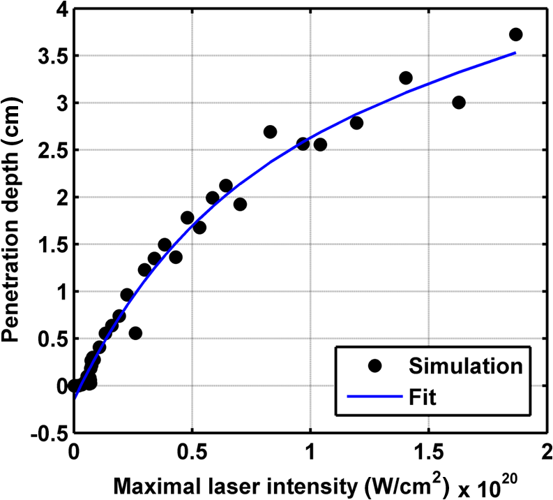
Figure 2 shows a schematic explanation of the simulation stages. 2.2.Tissue PenetrationElectrons penetrate matter to depths determined by the irradiated material’s density. On average, for therapeutic energy levels, radiated on water and water-like tissues, the typical energy loss is . Increasing the penetrated material density by a certain factor would cause the energy loss to increase by the same ratio.1 In the apparatus suggested, the electrons are accelerated inside a capsule. Since the capsule adds an additional layer for the electrons to pass through, its density and thickness are important factors in determining the electron’s energy when exiting the capsule and entering the tissues and could be changed to manipulate the desired radiation profile. Two representing test cases were chosen in order to demonstrate a patient-specific treatment profile. In the first test case, a 0.5-cm-diameter tumor was situated in an inaccessible location and could only be radiated from the outside. The second test case included a 1-cm-diameter tumor situated in an accessible location and optical waveguide penetration into the tumor was allowed. For both examples, the capsule was assumed to be made of glass, with a density of ,23 resulting in energy loss of [assuming tissue density of 24]. 3.Results3.1.Simulation ValidationThe simulation was validated according to the procedure described above. First, a single particle run was performed and the output results were compared to the expected path according to the literature. The main laser parameters used as input for this run were beam waist of , wavelength of , Gaussian pulse with a length of 100 fs, and maximal intensity of . The main simulation parameters were axis resolution of 1 nm, axis resolution of 0.1 nm, and 1700 cycles of 0.1 fs. The simulation output can be seen in Fig. 3. Fig. 3Representative results for the single particle run (laser beam waist of , wavelength of , Gaussian pulse with a length of 100 fs, maximal intensity of : (a) velocity at the axis direction, (b) velocity at the axis direction, (c) axis position, (d) axis position, and (e) electron trajectory.  As the figure shows, the particle oscillates and drifts in the -axis direction and drifts in the direction as long as the pulse affects it. The drift in the direction is a result of the Gaussian beam shape of the pulse. This behavior fits the descriptions in the literature.16 The calculated acceleration angle of the electron was calculated at the end of each cycle and compared to the theoretical values, as shown in Fig. 4. In order to improve graph clarity, only points that correspond to velocity peaks are shown. For the entire 1700 cycles, the root-mean-square (RMS) of the angle estimation error was 0.14%. Fig. 4Acceleration angle as a function of accelerated electron energy for the single particle run. Simulation results (dots) are compared to theoretical formula (line) at different times.  Figure 5 shows the comparison of theoretical and simulated acceleration angles as a function of electron energy after the laser pulse passed, for the same parameters as the single particle run, with the following changes: the number of cycles was 4999 to ensure accurate residual movement representation, and the laser intensities varied between and (55 points). Fig. 5Single particle final acceleration angle as a function of accelerated electron energy for various laser intensities. Simulation results (dots) are compared to theoretical formula (line). 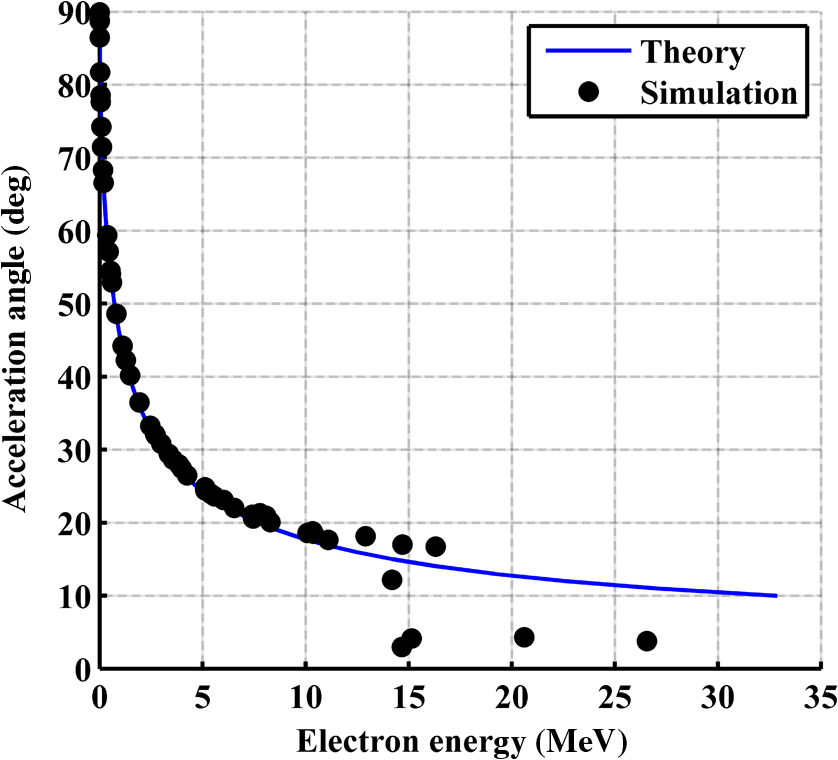 As the figure shows, there is a good correlation between the simulation and the theory for final particle energies . This corresponds to laser intensities lower than . The RMS of the angle estimation error in this range is 1.33%. The errors seen above this intensity may be caused by numerical errors, proton movement, or other neglected high-intensity phenomena. However, final electron energies of 8 to 10 MeV should be sufficient for evaluating the application described in this study. Figure 6 shows the dependence of the final electron energy [Fig. 6(a)] and acceleration angle [Fig. 6(b)] on the laser intensity. In order to simplify treatment design and to reduce the errors, a fit was found for each graph. Fig. 6(a) Final electron energy and (b) acceleration angle as a function of maximal laser intensity. Simulation results (dots) and fit (line) for the electron’s state after the pulse has passed.  For the electron energy, the fit equation is For the acceleration angle, the fit equation is It should be noted that these equations are relevant for the scenario simulated only. Any change in laser properties will change the results as well. The previous figures described the results of simulations with a single electron. However, in reality, the entire capsule volume should be filled with electrons. In order to calculate the acceleration patterns for all accelerated electrons, the simulation was run for a capsule filled with electrons accelerated by a laser beam. Figure 7 shows the electron density in space at different times after the simulation began. Fig. 7Electron density as a function of time for a full capsule during acceleration by laser pulse intensity of . The color scale represents densities as for graph clarity purposes.  As the figure shows, electrons outside the beam center had reduced acceleration energies and angles, reducing to zero at the top and bottom edges of the capsule. Further analysis shows that the final velocity distribution is relatively uniform and that electron velocities and acceleration angles fit Eq. (16). 3.2.Calculating the Requirements for the Test CasesAs Fig. 6 shows, the accelerated electron energy can be calculated as a function of laser energy for the described scenario. Using the known energy loss in tissues, the penetration depth into the tissue can be calculated as a function of laser intensity, as seen in Fig. 8. As the figure shows, with the limits of the simulation presented, the maximal penetration depth without considering the energy loss of the capsule is 4 cm, obtained by using laser intensity (although, with simulation improvement, deeper penetration depths can be planned). As mentioned, electrons lose energy as they penetrate matter. The extent of the lost energy depends on the density of the material irradiated. This factor can be used to add control to the radiation profile. A thicker capsule would allow only the more energetic electrons out, with reduced energy, but will maintain their original acceleration angle, which is steeper. Therefore, the penetration depth into the tissue can be reduced by increasing the thickness of the protective capsule. Using the data in Fig. 8 and the expected energy loss in a capsule glass, example treatment plans were designed for the two test cases presented. For the first test case, of a 0.5-cm-diameter inaccessible tumor, the following treatment plan was simulated and shown in Fig. 9: the laser was used to accelerate the electrons in five illumination points (marked as squares) equally spaced between and [tumor center was located at (1.48, 0.42) in this coordinate system]. At each illumination point, a laser intensity of was used. According to the findings from the full-capsule simulations, this means that electrons will be accelerated to velocities fitting this intensity and to lower intensities as well, creating a uniform area of radiation instead of a single line. Capsule thickness was chosen to be 4 mm (equivalent to 2.36 MeV energy loss for each electron). The radiated areas are colored and the tumor appears as a circle. The number and location of the illumination points was chosen in order to cover as much of the tumor area as possible. Fig. 9Suggested treatment plan for test case 1. Illumination points are marked by squares, the tumor is marked as a circle, and the calculated radiated area is colored.  The calculations presented here do not consider the scattering of the electrons to the side of the beam. This scatter is not significant but could potentially be enough to reduce the number of illumination points required to cover the tumor area. As the figure shows, most of the tumor can be covered. Another important aspect is that the electrons are actually accelerated in both the positive and the negative directions of the axis (assuming linear polarization in the -axis direction), due to symmetry. In this case, the capsule could be covered with lead or another high-density material on its lower side to remove the lower radiation lobe. Since the laser intensities involved are very high, it is interesting to estimate the expected temperature increase resulting from the laser pulse. For every pulse, the energy per pulse is approximately bounded by where is the pulse length, is the maximal intensity of the pulse, and is the beam width radius.As the results show, the energy delivered by each pulse is not . For 1 g of tissue, assuming a heat capacity of ,24 this is approximately equivalent to a temperature increase of 4.6 deg. For 1 g of glass with a heat capacity of ,25 this is equivalent to a temperature increase of 18.7 deg. Although the values calculated for the capsule absorption were slightly high, these temperature increases are manageable. For example, the heated area could be cooled by continuously flowing cooled saline solution outside the capsule. For the second test case, of a 1-cm-diameter tumor that could be penetrated by the optical waveguide, the following treatment plan was simulated and shown in Fig. 10: the laser was used to accelerate the electrons in 16 illumination points (marked as squares) equally spaced between and [tumor center was located at (1.1,0) in this coordinate system]. The laser intensities used were . Capsule thickness was the same as in the previous test case. The markings in the figure are the same as in the previous figure. Since the tumor in reality is three-dimensional (3-D), circular laser polarization can be used, causing conical electron emission and, thus, covering the entire volume of the spherical tumor. 4.DiscussionThe treatment designs for the presented test cases reveal the main advantages of the method. In both cases, the tumor area is radiated with margins in the scale of a few centimeters. This is significantly lower than the extent of the damage caused by the traditional radiation methods and is also somewhat desired, since malignant cells may be found outside the visible tumor borders. The reduced side effects are expected to improve treatment effectiveness, since higher doses can be given, thereby improving patient prognosis and life quality. Although some points inside the tumors seem to not receive radiation in these simulations, the natural scattering of the electrons in the tissue, though minimal, should probably allow electrons to cover them as well. The main obstacle in the realization of this method is the ability to transmit the high-intensity laser radiation to the required distances inside the body, which could range from several centimeters or more. At these extremely high intensities, breakdown phenomena begin to occur and conventional transmission may not be possible. However, this problem has several solutions that can be applicable, including focusing of the beam only near the acceleration point, the use of vacuum-filled waveguides, optical stretching of the pulse, and more. These methods are already widely investigated and their use for this application should be tested. Due to the high intensity, it is expected that some damage would be caused to the waveguide and the capsule at its distal tip. However, these parts can be designed for limited use during a single treatment session and replaced afterward. In order to facilitate the acceleration without causing damage to the tissues, the capsule at the tip of the fiber should be carefully designed. It should absorb or reflect most of the laser radiation (unless it is also used to damage tumor cells), while allowing the electron radiation to pass. Fortunately, the laser radiation propagates mostly forward, while the electrons have a perpendicular component to their velocity and their absorption spectra are also different. Therefore, the capsule can be designed accordingly, with thicker coated edges at the front and thinner, more transparent, edges at the sides. The capsule should also be designed to support the vacuum that is required in order to make the acceleration more effective. Another solution is to accelerate the electrons from a solid plate at the end of the waveguide. This acceleration method may allow for higher electron energies and enable proton acceleration at lower laser intensities. Using this type of acceleration target changes the way the laser is used to manipulate the radiation properties and should also be explored in the future.26 The laser polarization is another factor affecting the acceleration.26 The choice between linear and circular polarization affects the shape of the radiated region as well as the electron’s final energy. Ideally, the polarization could also be controlled in order to better design the patient-specific radiation profile. The simulation developed for this study was sufficient to demonstrate its properties but could also be highly improved. For example, better numerical schemes can be used to support higher intensities and the simulation could be improved to include 3-D representation and additional types of polarizations. Similar simulations do exist but are usually not publicly available. In addition, the electron transport in the tissue can also be incorporated into the simulation more accurately using available transport codes. However, the effect of this improvement is expected to be less significant. Another interesting possibility that should be explored in the future is the integration of the suggested method with the concept of creating -ray sources with laser acceleration. Previous studies have shown that lasers can be used to produce radiation sources in specific wavelengths which are optimized for absorption in nuclear structures dominant in malignant cells.26 For example, a similar efficient source was produced in the past and required electrons with similar energy levels and a 2-mm target for the -ray creation.27 As in the proposed method, this source allows for shorter treatment ranges and, therefore, reduces possible side effects. Its main advantage is the possibility to increase the specificity of the treatment by focusing on specific relevant wavelengths. However, it adds complexity to the system and the treatment ranges are shorter.26 A possible solution could be to use this source together with the electron source, thus increasing treatment effectiveness. 5.ConclusionsA method for internal electron therapy treatment was proposed. This method is based on transmission of a high-intensity laser to the tumor vicinity and acceleration of electrons according to a patient-specific radiation treatment profile toward the tumor. The proposed method was demonstrated on two test cases using simulations and shown to mostly radiate the tumor and not the surrounding healthy tissues. The results show that by using this method, good control of the radiation profile can be achieved while sparing most of the healthy tissues that would be irradiated using the conventional methods. Since this method holds the potential to greatly reduce the damage to healthy tissues, it is expected to have reduced side effects and to improve treatment efficacy, patient prognosis, and life quality. AcknowledgmentsMichal Tepper wishes to thank the Ministry of Science and Technology, Israel, for its support through her doctorate fellowship. ReferencesE. B. Podgorsak, Radiation Oncology Physics: A Handbook for Teachers and Students, International Atomic Energy Agency, Vienna
(2005). Google Scholar
T. Tajima and J. M. Dawson,
“Laser electron accelerator,”
Phys. Rev. Lett., 43
(4), 267
–270
(1979). http://dx.doi.org/10.1103/PhysRevLett.43.267 PRLTAO 0031-9007 Google Scholar
D. P. Umstadter et al.,
“Tabletop, ultrahigh-intensity lasers: dawn of nonlinear relativistic optics,”
Opt. Photonics News, 9
(7), 40
–45
(1998). http://dx.doi.org/10.1364/OPN.9.7.000040 OPPHEL 1047-6938 Google Scholar
G. Malka, E. Lefebvre and J. L. Miquel,
“Experimental observation of electrons accelerated in vacuum to relativistic energies by a high-intensity laser,”
Phys. Rev. Lett., 78
(17), 3314
–3317
(1997). http://dx.doi.org/10.1103/PhysRevLett.78.3314 PRLTAO 0031-9007 Google Scholar
K. Nakajima et al.,
“Observation of ultrahigh gradient electron acceleration by a self-modulated intense short laser pulse,”
Phys. Rev. Lett., 74
(22), 4428
(1995). http://dx.doi.org/10.1103/PhysRevLett.74.4428 PRLTAO 0031-9007 Google Scholar
A. Modena et al.,
“Electron acceleration from the breaking of relativistic plasma waves,”
Nature, 377
(6550), 606
–608
(1995). http://dx.doi.org/10.1038/377606a0 NATUAS 0028-0836 Google Scholar
V. Malka et al.,
“Electron acceleration by a wake field forced by an intense ultrashort laser pulse,”
Science, 298
(5598), 1596
–1600
(2002). http://dx.doi.org/10.1126/science.1076782 SCIEAS 0036-8075 Google Scholar
J. Faure et al.,
“A laser-plasma accelerator producing monoenergetic electron beams,”
Nature, 431
(7008), 541
–544
(2004). http://dx.doi.org/10.1038/nature02963 NATUAS 0028-0836 Google Scholar
M. Martin,
“Laser accelerated radiotherapy: is it on its way to the clinic?,”
J. Natl. Cancer Inst., 101
(7), 450
–451
(2009). http://dx.doi.org/10.1093/jnci/djp071 JNCIEQ Google Scholar
V. Malka et al.,
“Laser-plasma accelerators: a new tool for science and for society,”
Plasma Phys. Controlled Fusion, 47
(12B), B481
–B490
(2005). http://dx.doi.org/10.1088/0741-3335/47/12B/S34 PPCFET 0741-3335 Google Scholar
C. Chiu et al.,
“Laser electron accelerators for radiation medicine: a feasibility study,”
Med. Phys., 31
(7), 2042
–2052
(2004). http://dx.doi.org/10.1118/1.1739301 MPHYA6 0094-2405 Google Scholar
L. Laschinsky et al.,
“Radiobiological effectiveness of laser accelerated electrons in comparison to electron beams from a conventional linear accelerator,”
J. Radiat. Res., 53
(3), 395
–403
(2012). http://dx.doi.org/10.1269/jrr.11080 JRARAX 0449-3060 Google Scholar
K. Brüchner et al.,
“Establishment of a small animal tumour model for in vivo studies with low energy laser accelerated particles,”
Radiat. Oncol., 9
(1), 57
(2014). http://dx.doi.org/10.1186/1748-717X-9-57 RAONEU 0895-9943 Google Scholar
I. Gannot, O. A. Konoplev and J. Neev,
“Short-pulse delivery through HWG,”
Proc. SPIE, 3934 9399
(2000). http://dx.doi.org/10.1117/12.386352 Google Scholar
I. Gannot et al.,
“Broadband flexible waveguides for free-electron laser radiation,”
Appl. Opt., 36
(25), 6289
–6293
(1997). http://dx.doi.org/10.1364/AO.36.006289 APOPAI 0003-6935 Google Scholar
P. Gibbon, Short Pulse Laser Interactions with Matter, Imperial College Press, London
(2004). Google Scholar
D. D. Meyerhofer,
“High-intensity-laser-electron scattering,”
IEEE J. Quantum Electron., 33
(11), 1935
–1941
(1997). http://dx.doi.org/10.1109/3.641308 IEJQA7 0018-9197 Google Scholar
A. Pukhov,
“Strong field interaction of laser radiation,”
Rep. Prog. Phys., 66
(1), 47
(2003). http://dx.doi.org/10.1088/0034-4885/66/1/202 RPPHAG 0034-4885 Google Scholar
C. K. Birdsall and A. B. Langdon, Plasma Physics via Computer Simulation, Taylor & Francis, New York, NY
(2004). Google Scholar
T. Z. Esirkepov,
“Exact charge conservation scheme for particle-in-cell simulation with an arbitrary form-factor,”
Comput. Phys. Commun., 135
(2), 144
–153
(2001). http://dx.doi.org/10.1016/S0010-4655(00)00228-9 CPHCBZ 0010-4655 Google Scholar
D. Umstadter,
“Relativistic laser–plasma interactions,”
J. Phys. D Appl. Phys., 36
(8), R151
–R165
(2003). http://dx.doi.org/10.1088/0022-3727/36/8/202 JPAPBE 0022-3727 Google Scholar
J.-L. Vay,
“Simulation of beams or plasmas crossing at relativistic velocity,”
Phys. Plasmas, 15
(5), 056701
(2008). http://dx.doi.org/10.1063/1.2837054 PHPAEN 1070-664X Google Scholar
D. C. Giancoli and J. J. Boyle, Physics: Principles with Applications, Pearson Prentice Hall, New Jersey
(1997). Google Scholar
F. A. Duck, Physical Properties of Tissues: A Comprehensive Reference Book, Academic Press, London
(1990). Google Scholar
P. A. Tipler and G. Mosca, Physics for Scientists and Engineers, W. H. Freeman, New York
(2008). Google Scholar
D. Habs, T. Tajima and U. Koester,
“Laser-driven radiation therapy,”
Current Cancer Treatment: Novel Beyond Conventional Approaches, Intech, Rijeka
(2011). Google Scholar
A. Giulietti et al.,
“Intense -ray source in the giant-dipole-resonance range driven by 10-TW laser pulses,”
Phys. Rev. Lett., 101
(10), 105002
(2008). http://dx.doi.org/10.1103/PhysRevLett.101.105002 PRLTAO 0031-9007 Google Scholar
BiographyMichal Tepper received her BSc in physics-mathematics from Hebrew University, Israel, in 2002 and her MSc degree in biomedical engineering from Tel-Aviv University, Israel, in 2009. She is currently pursuing her PhD degree at Tel-Aviv University, Israel. Her research aims to develop optical and thermal noninvasive methods for tumor detection and treatment, tissue functional imaging, and assessment of physiological properties. Uri Barkai received his BSc in mathematics, computer science, and physics from Hebrew University, Israel, in 2002 and his MSc degree in computer science from Hebrew University, Israel, in 2008. He currently works as a software professional in the high-tech industry. Israel Gannot received his PhD from Tel-Aviv University in 1994. Between 1994 and 1997, he held a National Academy of Sciences postdoctoral fellowship. Since 1997, he has been a member of the Biomedical Engineering Department at Tel-Aviv University, where he served as a chair. Currently, he is also a research professor at Johns Hopkins University. He is a fellow of SPIE, ASLMS, and AIMBE. He authored around 70 papers, 100 proceeding papers, 8 book chapters, and 14 patents. |